Does anybody have information on a flat head hit and miss engine? I don't think I have ever seen one. Maybe they never existed. I am looking for a different type of i.c. engine to build. I have built many overhead valve hit and miss engines, side shaft hit and miss engines, horizontal engines, vertical engines, tee head engines, angle head engines, one two cycle engine, Atkinson engines, flame licker engines, sterling cycle engines, opposed piston engines, oscillating cylinder engines, and one flathead conventional engine. I woke up this morning thinking about flat-head hit and miss engines, and I don't ever remember seeing one.---Brian
You are using an out of date browser. It may not display this or other websites correctly.
You should upgrade or use an alternative browser.
You should upgrade or use an alternative browser.
Flathead hit and miss engine???
- Thread starter Brian Rupnow
- Start date

Help Support Home Model Engine Machinist Forum:
This site may earn a commission from merchant affiliate
links, including eBay, Amazon, and others.
Here is an interesting video of a Briggs and Stratton reconfigured to be a hit and miss engine, but the hit and miss is controlling only the ignition. This is not a true hit and miss engine, more of a "Make and break" engine such as used for Dorys on the east coast in the 1940's.
Here is a video much closer to what I have in mind. There is a set of centrifugal governors tucked in behind the flywheel that are moving a lever which locks out the exhaust valve and holds it open during the "miss" cycles. Although this engine still utilizes the original camshaft to open the intake valve, the intake could be atmospheric, so that no intake cam would be needed.
Using the ignition works fine but wastes fuel as the miss cycle is still drawing in fuel whereas the exhaust valve being held open does not waste an induction cycle . A small point but never the less the ignition cycle still uses the miss cycle to govern speed. An interesting project though Brian John
Here is a picture of a headless Witte. Is that what you’re looking for?


Thank you Oldiron, not quite what I had in mind but thank you for the effort.----Brian
I mentioned to Brian elsewhere that many of the vertical hopper cooled engines like the various Baker Monitors and the FM Eclipse are in effect flatheads in as much as the exhaust valve stem points towards the crank with many like the Witte having the valve in a block that fixes to the side of the cylinder but could be made from one if he wanted.
He wants air cooled which would be the basic same layout just don't fit a hopper and cut some fins into the head and cylinder. Probably easier to have a separate head than finishing a blind bore cylinder
He wants air cooled which would be the basic same layout just don't fit a hopper and cut some fins into the head and cylinder. Probably easier to have a separate head than finishing a blind bore cylinder
All Right!!!--Making this up as I go along. I'm going to design (and maybe build) a model flat head hit and miss engine. I have so many models of so many engines now, that I seldom start from scratch. My software lets me borrow any part from any previous engine and save it in a new file. As long as I rename the part when I save it to a new file, any changes to it will not affect the original model. I have borrowed heavily from my last horizontal hit and miss engine, because a lot of the parts can be re-used with no changes. Some of the parts will change, but any changes made in this new file won't affect the original files from which the part was borrowed.
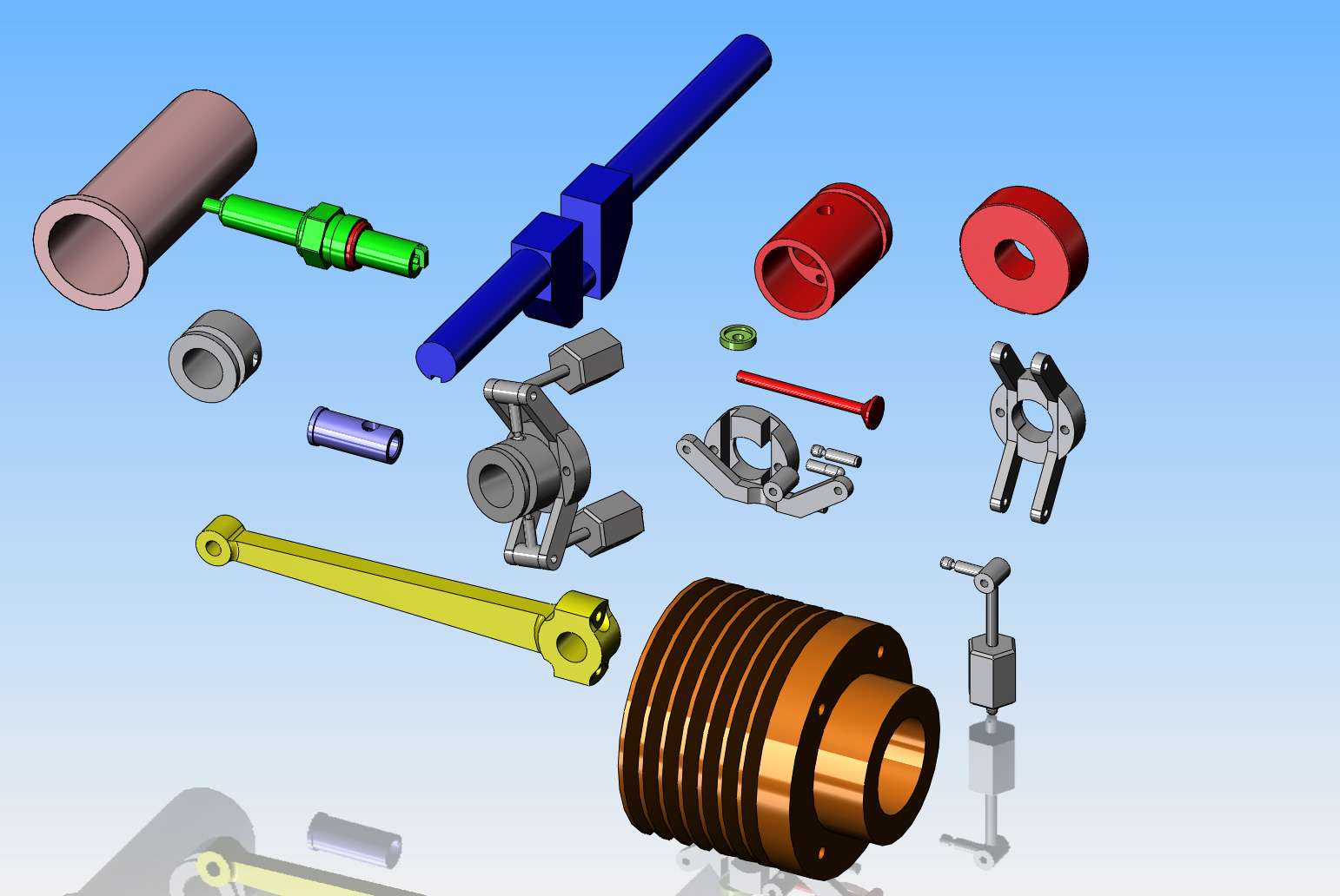

Yoweee---Do I know what I'm doing???--Not a bit. But I've got the morning in anyways---
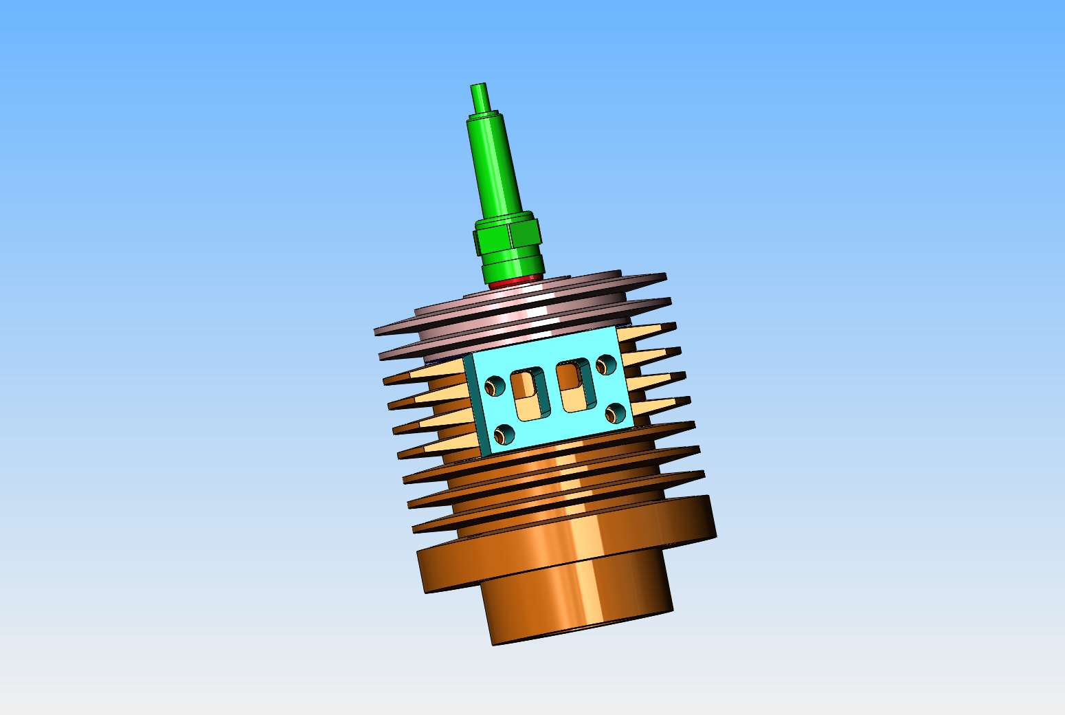

Hah!!!--Knew I could do it. The secret is all in the manifold block that attaches to the side of the cylinder. Intake valve stem faces up and is atmospherically actuated. Exhaust valve stem faces down and will be operated by exhaust cam or held open by hit and miss device.
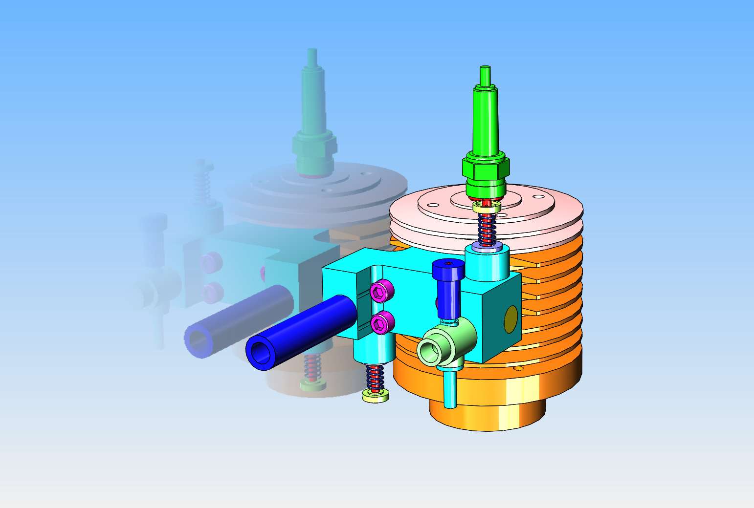

Okay, after some serious layout and shortening my con rod by 2", it appears that to have really effective cooling I will need the flywheel outer diameter to be made from a piece of 8" nominal schedule 40 pipe. I can probably cheat a bit and use a piece of 7" o.d. heavy wall tube. that depends on what my supplier has in stock.
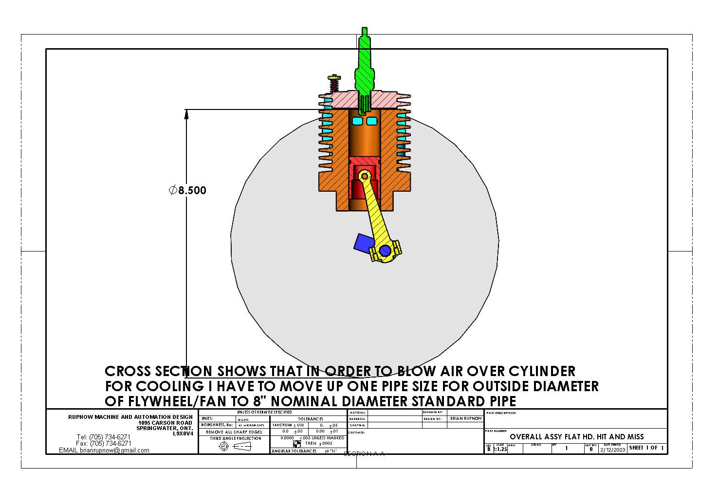

Brian, is that technically a flathead? I would have described this as a side-valve engine. Maybe they are the same thing??
UK call a Flathead a side valve.
Brian If you narrowed down that pale blue valve block you would have more of the fins clear and in the airflow, as it is that blocks quite a few fins. Fins along the top of the head would also aid cooling.
Do either the exhaust pipe or carb actually need to be turned through 90deg, you could just put them at the end of the block where you have for passage drilling blanked off.
Inlet valve could also face downwards more like a "Flathead" Briggs rather than copy the Monitor's layout
Also interested to see how your inlet passages work
Yes, that is technically a "flat head". Jason--I will look and see if the inlet and outlet ports should be rearranged. Johwen--Yes, I could do that, as I have on half a dozen other engines, but I was looking for something a bit different.---Brian
I'm a little late to this topic, Brian, have you looked at a Foos engine?
It's a brand new day, and just like Steve Earl, I've come back with brand new plan. The flywheel is going to be 8" o.d. with a 1/4" web and a 1 3/4" dia. hub. No bolting. The "blades" are going to be 1 1/4" x 1/8" x 1 1/2". All is steel and all is welded. All mig welded. This size will cool the engine I am designing without any trouble.
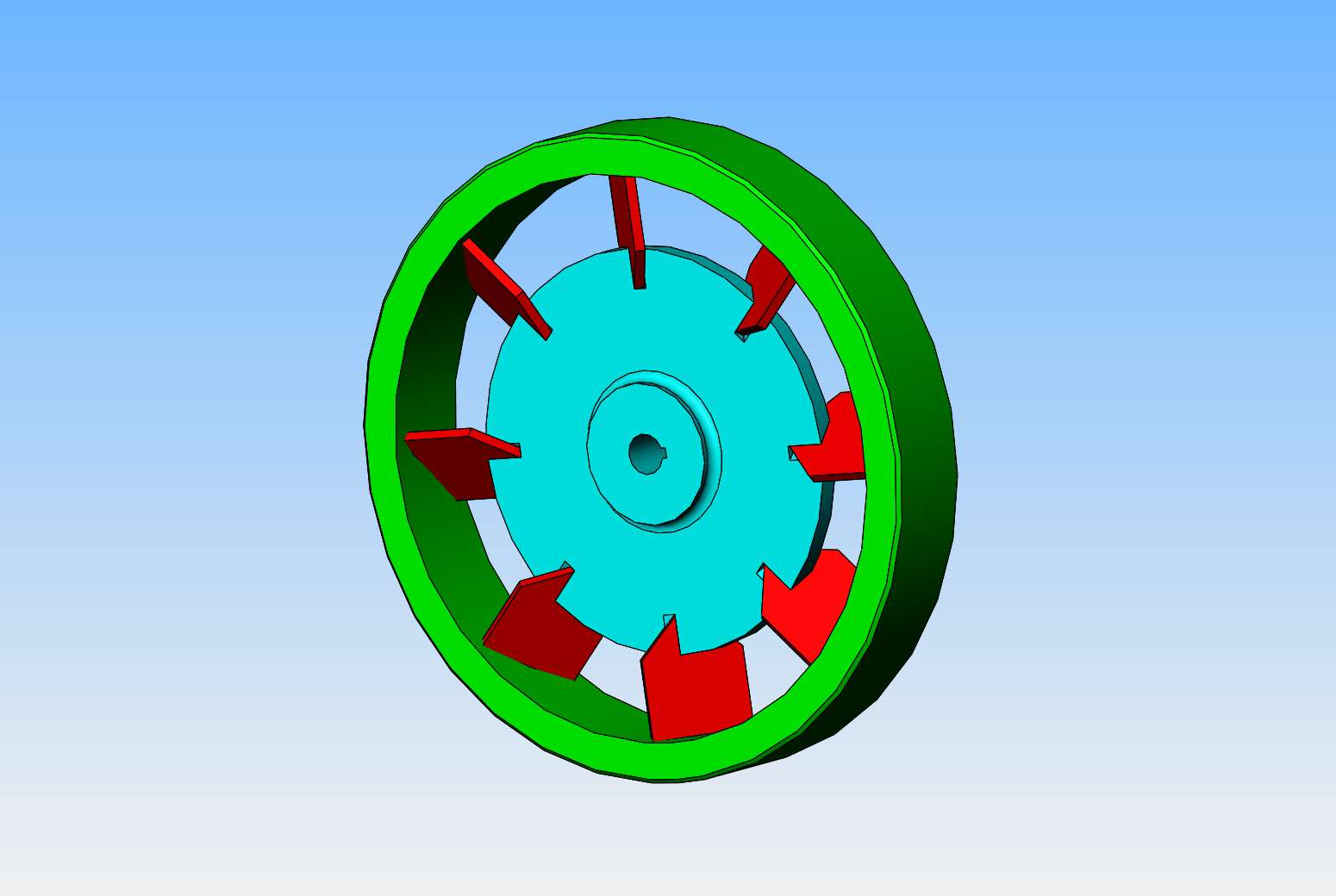
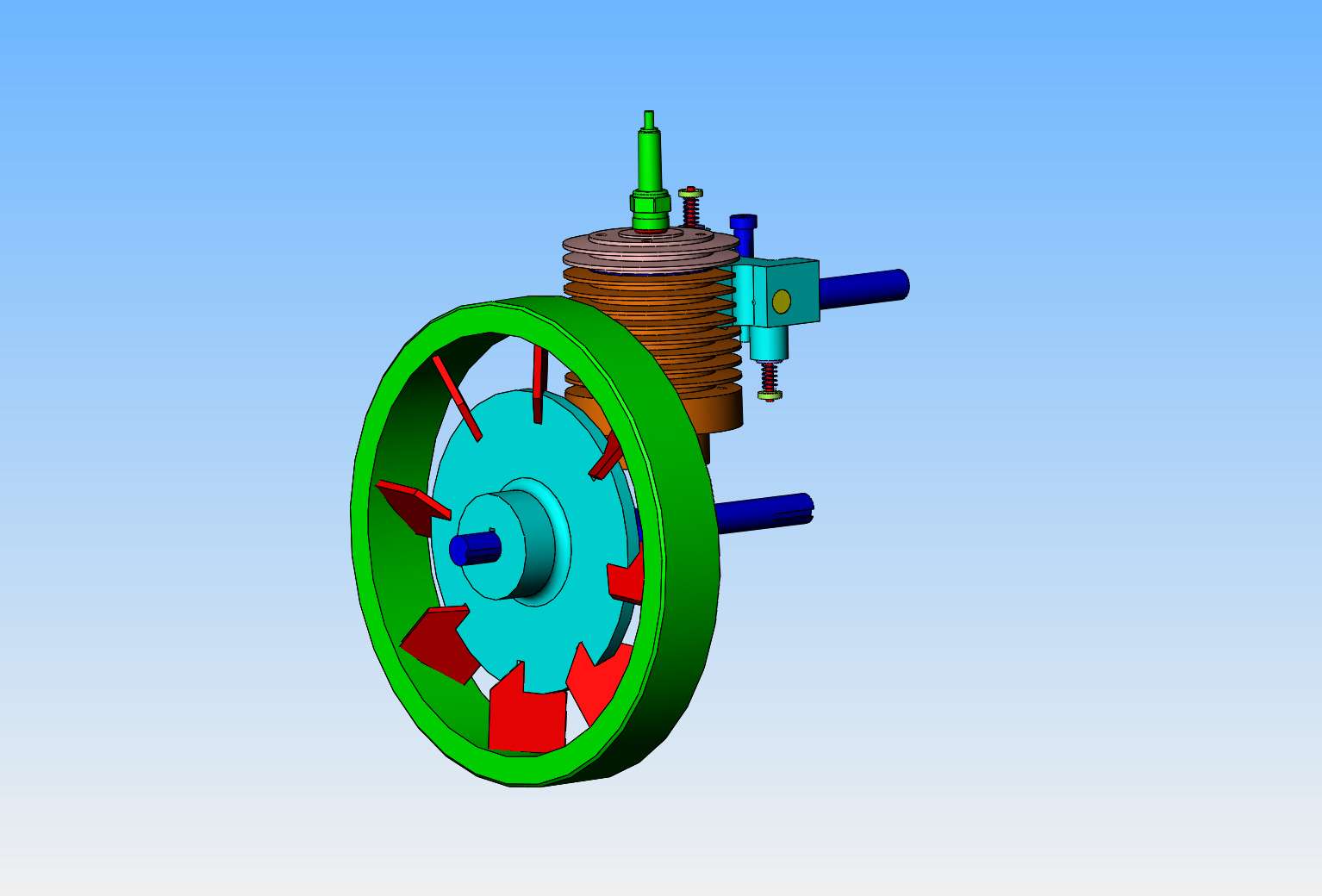


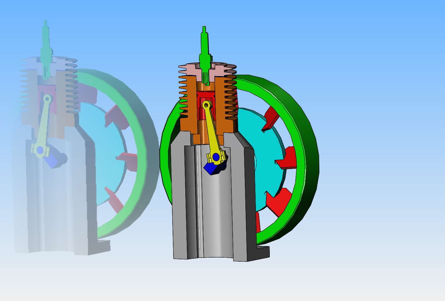
Beginning to get very, very weird, and yet it all fits and the crankshaft revolves without getting hung up. That base is made from a single piece of 4" square aluminum. It is tall like that to get clearance under the flywheel.

Mike1
Mike1
Brian, there seems to be a lot of wasted air flow over your cylinder fins,
could you have a stub shaft say on the centre line of you finned cylinder fitted with a smaller diameter fan which could be driven by a pulley fitted to the crank shaft and it could reduce the height of the engine, it's just a thought of mine and probably won't work but I enjoy watching your work come together.
Mike1
Hi Mike--Yes, I could easily do what you suggest. I'm just playing, seeing what other forced air cooling arrangement I can do.
Similar threads
- Replies
- 0
- Views
- 560
- Replies
- 19
- Views
- 5K
- Replies
- 356
- Views
- 54K


