Flat Belt Reversing Mechanism

Home Model Engine Machinist Forum

Help Support Home Model Engine Machinist Forum:

This site may earn a commission from merchant affiliate links, including eBay, Amazon, and others.

Brian Rupnow

Design Engineer
Project of the Month Winner
Joined
May 23, 2008
Messages
14,969
Reaction score
8,247
Location
Barrie, Ontario, Canada
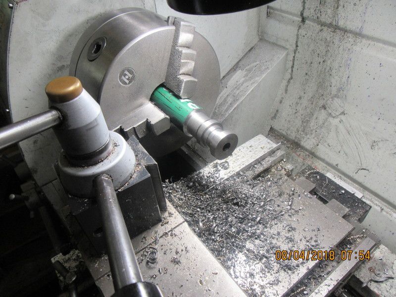
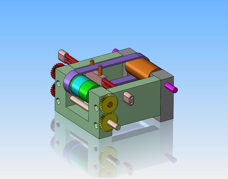
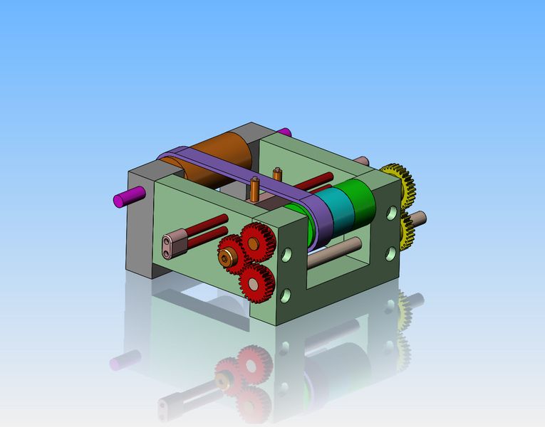
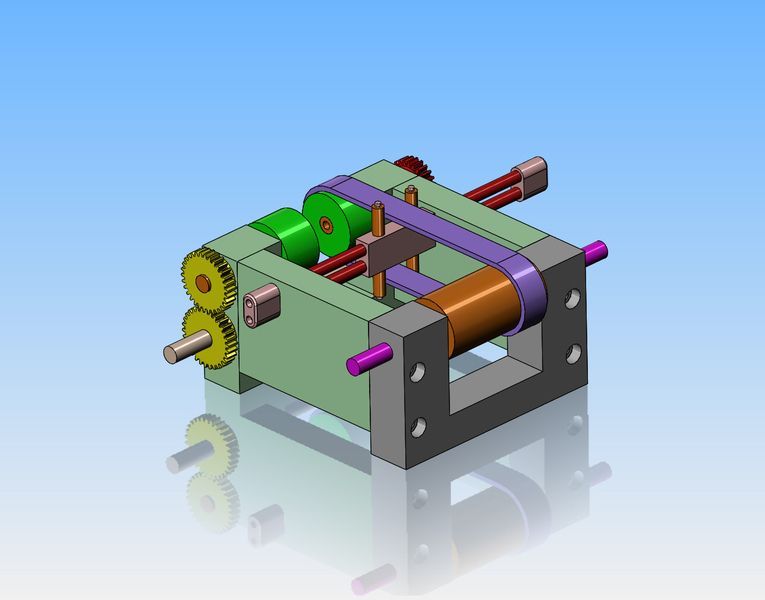
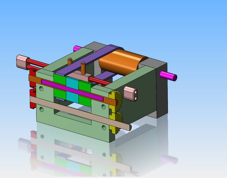
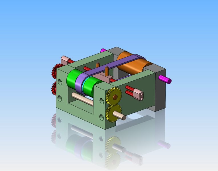
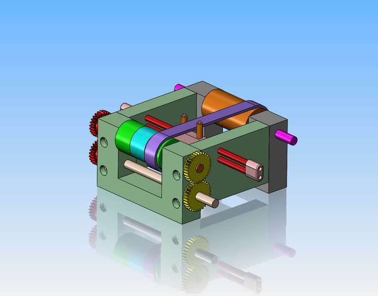
With the end of every project, I declare that I've had enough machining, and I'm going to take a break for a couple of months. Then I lay in bed at night, and it isn't sugar plum fairies that dance thru my head---it's machinery!! One of the things that fascinates me is how they shifted flat belts pulleys into reverse on the old lineshaft machinery. I've seen pictures of it but never have seen it done in "real life". I just happen to have a small flat belt, about 5/8" wide x 0.100" thick that I scavenged from somewhere, and time on my hands. So--I spent this morning modelling a flat belt reversing mechanism. In the attached picture, the power is input to the beige colored counter-shaft in the lower left hand corner. This will make the gear which meshes with it rotate in the opposite direction and carry the green pulley closest to that gear and the shaft it rides on with it. However, the belt is at the other green pulley on the far side from the yellow gear, so what's going on here?
qomwIh.jpg
 
If we look at the mechanism from the other side, we see that since there is an idler gear between the countershaft gear and the driven pulley gear, the green pulley on the far side will always be rotating in reverse to the first pulley we seen over by the input end of the countershaft. And in the picture as shown, the pulley will be driving the flat belt and the pulley at the far end.
SorzV7.jpg
 
Now there is a trick here at the end with three pulleys. The center pulley and shaft which it rides on are not driven from either side. The center pulley and shaft just free-wheel. The two outside driven shafts are hollow. The shaft with the center pulley on it is supported by the two outer driven shafts, but it is not keyed to them. The center pulley and it's shaft free-wheel. The second picture posted is actualy a section taken thru the 3-pulley shaft, to show how this is arranged.
9pTxUL.jpg

iV8nF1.jpg
 
This picture shows the belt shifted to the center pulley which is the neutral position. Since no power is being transmitted to the shaft which supports the center pulley, the belt will not be driven.
w1Hq32.jpg
 
So, what mechanism is used to move the belt into one of it's three possible positions? (note that the pulley at the far end has the same overall length as the three shorter pulleys combined) The belt shifter mechanism. This shifter mechanism can be moved by means of a lever, a screw, or even finger power in this case. It is guided in it's travel by matching holes in the two side frames. Since the top run of belt and the bottom run of belt are moving in opposite directions, the bronze colored rollers which contact the sides of the belt must be able to revolve independently, one clockwise, the other counter-clockwise.
dvY8ee.jpg
 
And here is a final picture, in which the belt has been moved to the opposite side pulley from the very first picture posted, so the belt will be rotating in the opposite direction from the very first picture posted.
T2y4VW.jpg
 
Will I actually build this?--The answer is "probably". I never have much "real work" in the summer time, and although my good wife and I have some small day trips planned this summer, that is still going to leave me with a lot of time on my hands.---Brian
 
Another intriguing mechanism. This will be interesting to see built (of course I have no doubt you'll built is, you've probably already got the first part made...).
 
I must be getting Old , I worked on flat belt lathes as an apprentice. if you got things right . you throw the lathe on. then shift the leaver into reverse and the 3 meter belt would jump off the top pulley . and then you had a nice long rest until the maintenance crew came to put it back on again . I worked for Churchill Machine tools in the UK way back in 1962
 
One of the first things I had to do was to measure the true center to center of the belt when it was on the pulleys. I made up all four of the pulleys this morning, then took two into the machine shop. I zeroed out the quill using my DRO with the long pulley clamped in my vice, then locked the y axis and moved the table in the x axis until I could get the belt on both pulleys. The height of the quill was lowered to match the pulley in the vice. Then it was simply a matter of cranking the table in the X axis until I felt that the belt had proper tension on it. The center to center turned out to be 5.167".
pCsNSj.jpg
 
Mortimer was that Churchill -Matrix ?
Dan.
 
I think maybe Abby posted in the wrong thread. I found a left over piece of cast iron large enough and long enough to get two 30 tooth gears out of. I like to do all my turning to size and boring the center hole all in one set-up. Tomorrow I will cut both gears at once in one set-up, then part them off as individual gears after all the teeth are cut.
N17hDv.jpg
 
I don't think the mechanism is nearly as precise or complex as you think. Take a single machine where the motor is on the machine and drives the drum. The drum has two flat belts which can be moved over to one of three positions. One of the belts is crossed over for reverse and drives a 'fast' pulley which is fixed to the shaft. The other belt drives the 'loose' pulley which just spins around on the shaft, sorta like a neutral position. The pulleys are now in 'reverse'. To change to forward, the belts are moved over as a pair. The crossed belt is now on the 'loose' pulley and the uncrossed forward belt now drives the pulley shaft.
The belt is moved via that shifter mechanism. The belts are not tight, and the belts are moved slowly. I'll will dig out some photos of the drive overhead at the local blacksmith museum.
 
You might want to take a look at an old flat belt log sawing machine and how they reversed the carriage for the next cut.
I have an old sawmill in pieces that I would like to put together one day.
Some pieces are broken so I will have to research that subject one of these days.
For power it uses a big old GM 3 cylinder Detroit Diesel engine.
Might be a short cut or simplification in there for you???
 
This morning we get to do the whole thing over again. These two blanks are for the 25 tooth gear. I lucked out this time and found some 1144 stress proof. Next step will be to mount the rotary table and indexing plates onto the mill and cut some teeth. I might actually drill and tap all the gears for grub screws before I cut the teeth and part them off. I'm not concerned about the 1144 stress proof steel, but cast iron can always be a pig and 'break out' when you are tapping close to the edge.
fRIU1S.jpg
 

Latest posts

Back
Top