


Sshire
Well-Known Member
- Joined
- Jun 29, 2011
- Messages
- 936
- Reaction score
- 259
The carriage feed/leadscrew project is finished.
Thanks to all here who contributed suggestions and technical advice.
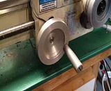
Having the speed of the carriage separate from the spindle speed is a treat! Even at slow speeds, the finish is greatly improved because I can really slow the feed speed down to a very low rate (I keep looking at the hand wheel to see if it is turning)
A short video to show the slowest speed and the control box.
I wanted to try direct drive and if that wasn't satisfactory, I'd go to cogged pulleys and a timing belt.
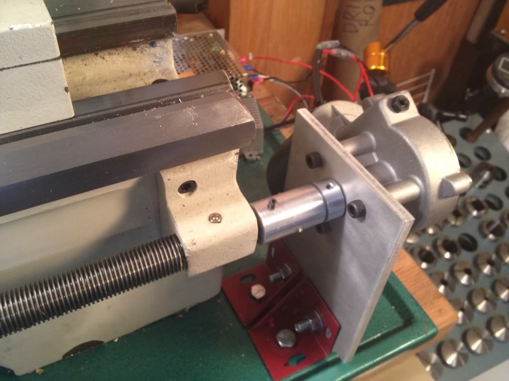
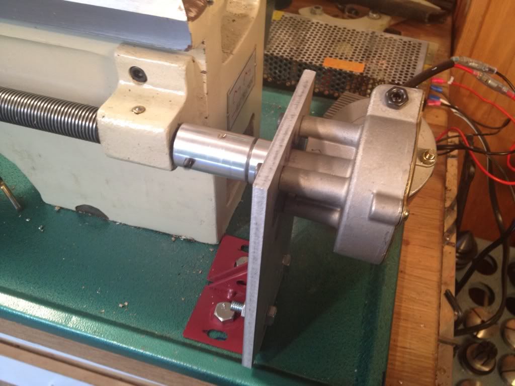
This is the geared motor mounted to the leadscrew. The mounting plate is 6061 (3/8"), the red brackets are leftovers from trashing the Harbor Freight 4x6 bandsaw stand.
The pieces to couple the motor to the leadscrew with a brass shear pin.
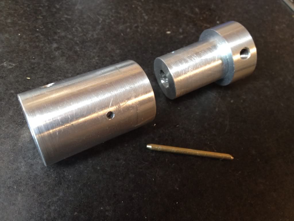
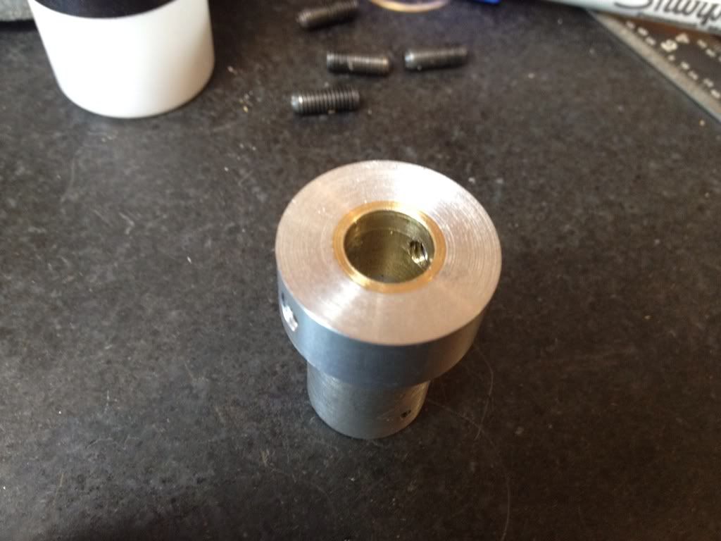
The motor shaft coupling. The brass bushing is: A: more practice in making and press fitting bushings and B: a fix for the 0.10 overbore.
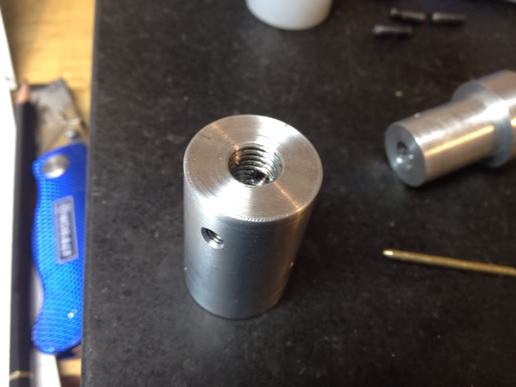
The threaded coupling to the leadscrew.
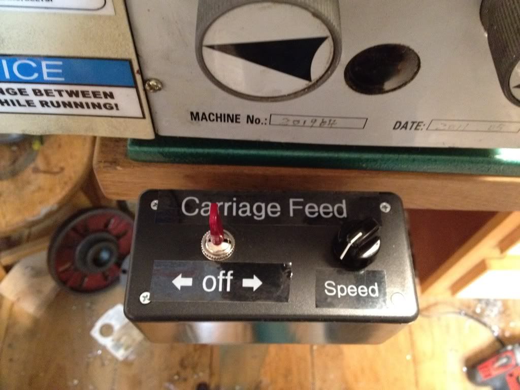
Control box with reversing switch and speed control all connected to the PWM module.
A worthwhile project for me. About 8 hours total. I still have the carriage stop with power cutoff to complete. That will be later in the week.
Thanks again so much for the help and suggestions. Now I can get back to Elmer's Radial.
Stan
Thanks to all here who contributed suggestions and technical advice.
Having the speed of the carriage separate from the spindle speed is a treat! Even at slow speeds, the finish is greatly improved because I can really slow the feed speed down to a very low rate (I keep looking at the hand wheel to see if it is turning)
A short video to show the slowest speed and the control box.
I wanted to try direct drive and if that wasn't satisfactory, I'd go to cogged pulleys and a timing belt.
This is the geared motor mounted to the leadscrew. The mounting plate is 6061 (3/8"), the red brackets are leftovers from trashing the Harbor Freight 4x6 bandsaw stand.
The pieces to couple the motor to the leadscrew with a brass shear pin.
The motor shaft coupling. The brass bushing is: A: more practice in making and press fitting bushings and B: a fix for the 0.10 overbore.
The threaded coupling to the leadscrew.
Control box with reversing switch and speed control all connected to the PWM module.
A worthwhile project for me. About 8 hours total. I still have the carriage stop with power cutoff to complete. That will be later in the week.
Thanks again so much for the help and suggestions. Now I can get back to Elmer's Radial.
Stan