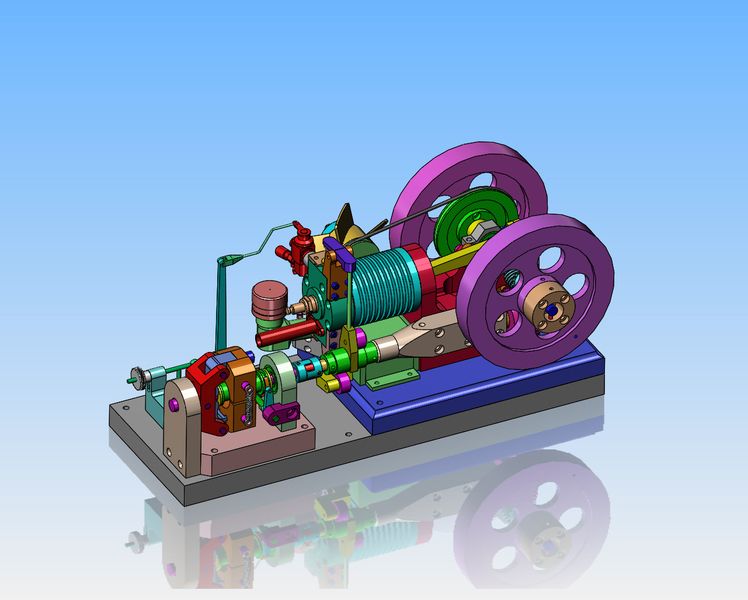
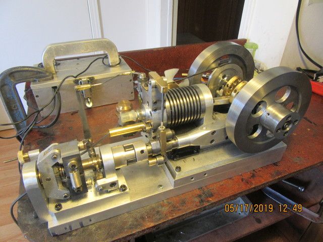
And for Luc---You were right. The governor only needed the one spring to work correctly. I built this governor almost exactly to the original drawings by Edgar Westbury, as shown on the first page of this thread, and he showed two springs, so that's what I did. I have always followed the principle that if I`m not really sure, go by the drawing. If I have to tweak things a bit after something is built, I will.---Brian