ENGINE SPEED GOVERNORS

Home Model Engine Machinist Forum

Help Support Home Model Engine Machinist Forum:

This site may earn a commission from merchant affiliate links, including eBay, Amazon, and others.
Nelson--I have always been interested in mechanical feedback speed control devices. It will be interesting to see this one work.
 
I do not know if it would make a whole lot of difference but the spring mounts on the side of the governor if they were cut on an offset they could be tensioned or loosened with just a turn on the holders. That is one special governor, I fell in love with it. Thanks for sharing.
 
Here's a little tip on threaded spring tensioners like the one in my model. If you make them as a single threaded shank with an eye at one end, they will rotate when you tighten or loosen the adjustment finger wheel. If however, you make them as seen in this model with a double shank and slot the piece they pass thru, then they won't rotate when you are trying to adjust spring tension.
OspUbf.jpg
 
Edgar Westbury called up #20 swg. for the springs which keep the flyweights together. 20 swg (which I assume to be "standard wire gauge") is listed as being 0.036" wire diameter. The closest I could buy to that is actually 0.038" diameter wire. It feels like it would take seven men and a bulldog to pull the flyweights apart with these springs in place, but we're in "Try it and see" mode here. I'll let you know how that works out. The rather puny looking tension spring on the left is one I had selected out of a 200 piece spring kit that I had, but it looks pretty wimpy beside the .038" springs.
SfSZ26.jpg
 
This governor has four arms with hubs on them. I decided that the easiest and most accurate way to make them was to make the arms and hubs as separate pieces and then silver solder them together. These pieces are way too small to hold in the correct relationship for soldering, so I made up a couple of jigs from short pieces of .093 " round-bar, some round 3/16" stock, and scrap aluminum. The aluminum is counterbored by the amount which the hub runs past the arm it is mated with, and the 3/16" round rod keeps things from tipping and getting crooked while being soldered.
CxjHs7.jpg
 
Well, that didn't turn out too shabby at all!! Everything fits where it's supposed to. I'm coming right down to the short strokes on this governor. I only have a couple of pieces left to machine.
sPOvLA.jpg
 
And here we have a video of the first dynamic test of the governor mechanism. I am pleased with the results. I still have to make an adjusting screw and knob for the counter-spring, but it seems to work exactly as I hoped it would.---Brian

the video is very nice, do yourself a favor,remove the spring from your counter weight, all you need is one
 
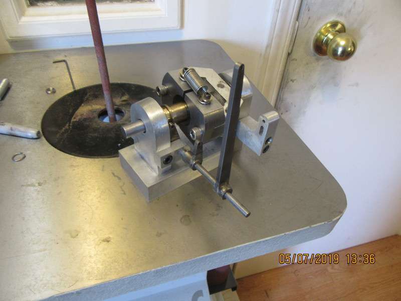
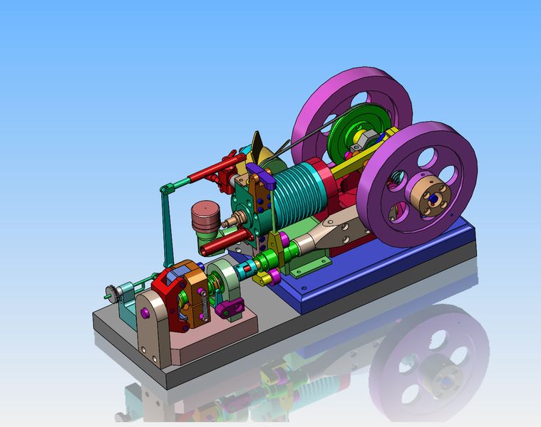
An observation---The governor seems to want to start moving the arm at about 650 rpm. This initial test was made with the counter-spring at it's maximum setting. I am assuming that if the counter-spring was adjusted to not have so much tension on it, the arm would start to move at a lesser rpm. (Hopefully I will find that out tomorrow.) This governor was designed to run off the cam shaft of an engine. The part that I find interesting is that my engines generally idle at about 1000 rpm, and there power band is around 1400 to 1500 rpm. The cam shaft rotates at 1/2 of the crankshaft rpm. --So, it seems that the governor engaging at 650 rpm fits right in with a 1300 rpm crankshaft speed. This could be purely coincidental, or it may be that Westbury actually made this governor, and the spring size he specified for the flyweights is based on actual testing at the time it was designed.
 
I lay in bed last night thinking of just how this throttle was going to work. If there is anything a bit fishy about this throttle governor, it is the fact that when the engine is shut off, the governor parks itself with the throttle held wide open. I don't like the idea of having to start the engine with the throttle wide open and waiting for the governor to spin up to speed to close the throttle. The answer would be to find a way to disengage the governor when the engine was at rest. Without going thru a complex bunch of maneuvering to install a clutch between the governor and the engine camshaft, I have an idea. If the link between the governor and the throttle arm were made as shown here, I could use a mechanical means to lock the carburetor throttle in the closed (idle) position. The governor would still work as expected, but instead of moving the throttle arm, the spring in the linkage would simply compress and not move the throttle arm. As soon as I unlocked the mechanical throttle over-ride, the governor would once again turn to it's normal function. thinking--thinking---
6lcwDm.jpg

MU2Mz4.jpg
 
[QUOTEI . If there is anything a bit fishy about this throttle governor, it is the fact that when the engine is shut off, the governor parks itself with the throttle held wide open. I don't like the idea of having to start the engine with the throttle wide open and waiting for the governor to spin up to speed to close the throttle. -

[/QUOTE]

Brian that's the way a governor work on all small engine . As soon as your engine will start that governor will kit in.
but then again that spring on your counter weight simply make it harder for it to reac.
nice work
 
More dynamic testing this morning showed that what I thought is true. The less tension there is on the counter spring, the sooner the lever moves at less rpm of the spindle.)
 
This is going to get very interesting. I ordered a 3/8" Lovejoy coupling today, and I will use it to connect the camshaft of the horizontal sideshaft engine I just finished to the governor, all on a common base. The engine will eventually drive something with a varying load to see how the governor responds.
mui5oZ.jpg
 
Just for the heck of it, at the end of my very long install a dishwasher at my oldest son's house day, I thought I would try this set-up. Driving the governor at 1:1 ratio off the crankshaft to see what would happen. What happened was that even at idle speed the governors swung out to their largest travel and no amount of tightening or loosening the counter spring would make them return to the "parked" position in close to the center spindle. Okay--driven at 1:1 off the camshaft they will be turning at half this speed. I'll let you know what happens when driven from the camshaft.
DeeKqp.jpg
 
Today I rearranged things a bit and drove the governor with a 1:1 ratio from the camshaft. Very pleased to report that when driven off the camshaft, the governor will both engage and disengage by changes in the engine speed resulting from changes in the throttle setting. Yesterday I tried this same trial by running the governor off the crankshaft, but the governor was driven so fast that it would not disengage regardless of what engine speed I was able to achieve.
 
So there we have it, and its a beautiful thing. The engine is bolted to the sub base. The governor is just setting in the correct position, but not bolted down yet. I will wait until I have the Lovejoy coupling in place between the engine and governor before I drill and tap the holes which mount the governor. I did some more testing of the governor attached to the camshaft via pulleys and belt like shows in my last video, and I'm quite comfortable now that the cam shaft turns at the right speed for engagement and disengagement of the governor with slight variations in engine rpm.
Dy1dx6.jpg
 

Latest posts

Back
Top