Enco (Rong Fu RF30) Mill/Drill Conversion

Home Model Engine Machinist Forum

Help Support Home Model Engine Machinist Forum:

This site may earn a commission from merchant affiliate links, including eBay, Amazon, and others.
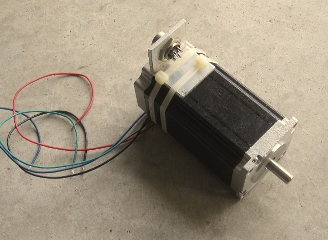
Chuck, that is good placement for your "Y"motor. Good thinking. On my conversion the pulley for the "Y" limits the travel a little, making parts with just over 8" in the "Y" impossible.

You may want to also check out the pulley size for the "Y" so this doesn't happen to you. You will want all the "Y" you can get.

maury

Thanks, Maury, the pulley on the Y-axis sticks out far enough that clearance isn't an issue.

Luc, thanks for the tip. I'll give that a try when I get the drivers and motors hooked up.

Shepdog, you're welcome to whatever drawings I have, although I don't know if they'll be any help to you unless your machine is substantially the same as mine...

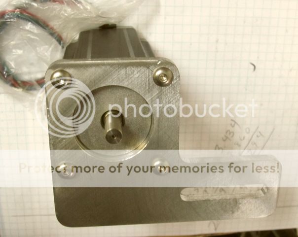
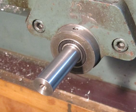
The angular contact bearings came in the mail today so I spent the rest of the afternoon and evening getting those installed. Since I was installing the bearings in the original bearing block casting, I went very slowly and was very careful not to screw something up. I did have one close call... I was very near the final OD and decided to press the bearing in and see how it fit. It wasn't real tight, but getting it back out was a wooley booger! I did finally get it out and bored the opening a little bigger so it is a sliding fit with no slop.

I also installed a regular ball bearing on the motor end of the X-axis ball screw. All the feed thrust is on the other end of the table which has dual thrust bearings, so this end just needs to handle the radial force from the belt. Also, in addition to the set screw which holds the extension onto the Y-axis ball screw, I put some Loctite 620 on it and also pinned it with a roll pin.

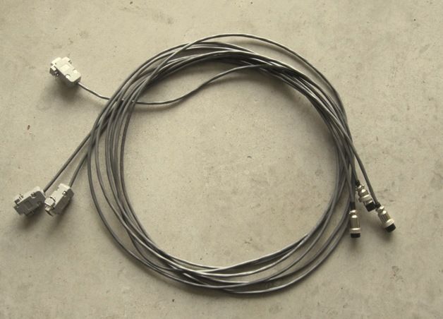
So, I ordered some connectors like these:

4Pin-PlugAndJack-apart_800.jpg


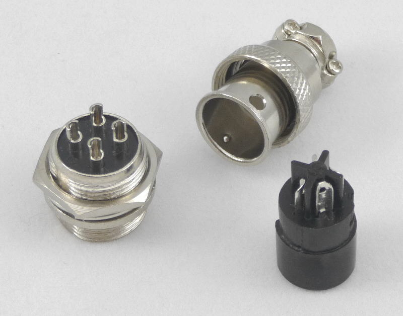
to connect the motors to the cables. I'm currently planning on using 4 conductor , 18 gauge stranded wire for the cables. Is that what most folks use? I'd like to use coiled cable like they used to use on telephone handsets, but have no idea where to find anything like that in the gauge I need. The other end of the cables want DB9 connectors for the Gecko G540.

Chuck
 
Thanks, Steve. The motor inductance is 6.8 mh per phase, 1.6 ohms resistance and are rated at 3 amps. The holding torque is 280 N cm which converts to about 396 oz in. I bought a 24v, 15 amp power supply specifically for this application, but could buy a different if there would be a significant performance boost. The driver is a Gecko G540 and will handle up to 50 volts DC for the motors.

As you said, speed is of little consequence to me. I have 20 tooth pulleys for the motors and either 48 or 60 tooth pulleys for the ball screws.

Here's the Y-Axis motor mount. It will be attached to the mounting arm with two 5/16" bolts through the 1 5/8" long slot. The bolts will be 3/4" apart which will give me 3/4" belt adjustment.

IMG_3151_zps2396b611.jpg


I realize this could still slip, but with two bolts holding it, it should be much more secure.

Chuck

according to the math the drives would want 83 volts. The drives you selected max out at 50. You might be happier with a 48 volt power supply if you can find one.

Also something to think about. You probably bought one of those regulated power supplies. They try to maintain a constant output. The gecko drive is going to be taking an input voltage and trying to turn that into a constant current to the motors. Sometimes the two will try to fight each other and you might get some erratic behavior or some missed steps that are random. Best power supply for the geckos is a simple supply using a transformer, rectifier, and some capacitors.

Thanks, Steve. I do have a large Variac that I can dial anything from 0 - 140 volts at up to 30 amps. I've also got some pretty beefy bridge rectifiers that will handle up to around 25 amps. I guess all I need is a large capacitor and I'm set. Wonder if I'll have any problem with grounding?

Chuck
 
Thanks, Steve. I do have a large Variac that I can dial anything from 0 - 140 volts at up to 30 amps. I've also got some pretty beefy bridge rectifiers that will handle up to around 25 amps. I guess all I need is a large capacitor and I'm set. Wonder if I'll have any problem with grounding? Chuck

Whoa Chuck, you don't want to use a Variac here! Most variacs don't isolate from mains, I'd much prefer that you go with a regular step down transformer. That and an inadvertent adjustment would likely fry things. The trick here is to find the right voltage output to keep you comfortably under the drivers maximum voltage. You could also wind your own transformer if you are into that sort of thing. I know sourcing the correct transformers is a pain, that is one reason why buying a transformer from a CNC parts vendor is so popular.

Another issue, as DC voltages increase you need to be far more careful with respect to your safety. The possibility of electrical shock will become an issue at higher voltages. I mention this only because people are less cautious around the common 24 VDC and less supplies and often forget to be safe when higher voltages are present.

Thanks for the warning, Wizard. I'm always a little concerned about using variac's to run anything other than a motor. Can you point me to any vendors who sell transformers?

Chuck
 
Steve--- how did you come out with this number:confused:

You can read the whole story on the Gecko website but here are the highlights.


The voltage of your power supply is entirely dependent on the inductance rating of your motor, which we learned is translatable to the number of turns of wire in the stator. Every motor model will have a different inductance rating and will therefore have a different maximum voltage. To figure out what the maximum power supply voltage should be, use the following formula with the motor’s inductance in millihenries (mH) used for the L value.

32 * VL = VMAX

If you are using several different models of motors on the same power supply use the lowest inductance rating in the above formula. This will ensure that your motors will not overheat due to the voltage being too high.


I think my drives are fed with some 60-65 volts but my drives max voltage is 80. Chucks is only 50 so cant exceed that ever. In his case I would go 48 if possible. To get 48 DC the ac input voltage needs to be about 34 volts. CNC suppliers have some wierd voltage transformers so its possible but not likely. At any rate he will need about 125Watt minimum if he uses the 4th. Also will need a 1500-2000MFD capacitor as close to the input of the drive as possible.
 
Hi Chuck

I have been enjoying your CNC conversion; thanks for taking the time to post your progress.

I converted my kneed mill years ago with an AhHa system (long out of business);p about 3 years ago I started a project to upgrade to servos, MACH and a quill drive. Originally I only did the X and Y.
Things kind of got side tracked and well here I am 3 years later getting going on it again.

I was able to get my old controller interfaced with MACH using a break out board from Homan Designs; what a major improvement from the old DOS program both in functionality and speed. I was able to double my rapids using MACH.

I curious to see how you handle your operator interface control panel etc.

I have resurrected my project and hope to make some progress on it this winter.

Thanks again for keeping us updated on your CNC project.

Dave
 
Last edited:
Thanks for the update, Steve. For the time being, I will plan on using my 24 volt switching power supply. I'll look to upgrading to a transformer system if I run into problems.

Another question, what are you CNC guys using for CAM? I'd like to keep my CAM cost under $300 if possible. Most of my work can probably be handled by 2.5D but might want full 3D from time to time.

Chuck
 
Hi Chuck

I use BobCAD it's quirky but capable; even if you haggle with them I'm not sure you could get it for $300.00 There are other low end solutions but I haven't tried any of them. It will be interesting to see what others are using.

Dave
 
Another question, what are you CNC guys using for CAM? I'd like to keep my CAM cost under $300 if possible. Most of my work can probably be handled by 2.5D but might want full 3D from time to time.

Chuck------- D2nc works great for $78.00
http://www.d2nc.com/html/purchase.html

artsoft for Mach 3 works well also
http://www.machsupport.com/software/mill-wizard-beta/

and their is also an addon for Mach3
http://www.machsupport.com/software/mach3-addons-for-mill/

If you are planning in trying JOG MODE you might want to download different screen set for Mach3
http://www.machsupport.com/software/downloads-updates/screensets/

enjoy
Luc
 
You can read the whole story on the Gecko website but here are the highlights. The voltage of your power supply is entirely dependent on the inductance rating of your motor, which we learned is translatable to the number of turns of wire in the stator. Every motor model will have a different inductance rating and will therefore have a different maximum voltage. To figure out what the maximum power supply voltage should be, use the following formula with the motor’s inductance in millihenries (mH) used for the L value. 32 * VL = VMAX If you are using several different models of motors on the same power supply use the lowest inductance rating in the above formula. This will ensure that your motors will not overheat due to the voltage being too high. I think my drives are fed with some 60-65 volts but my drives max voltage is 80. Chucks is only 50 so cant exceed that ever. In his case I would go 48 if possible. To get 48 DC the ac input voltage needs to be about 34 volts. CNC suppliers have some wierd voltage transformers so its possible but not likely. At any rate he will need about 125Watt minimum if he uses the 4th. Also will need a 1500-2000MFD capacitor as close to the input of the drive as possible.

Actually he can come close fairly easily, 48 VDC is a fairly common bus voltage in the controls world. The trick is finding supplies suitable for motion control work. Searching for 48 VDC power supplies brings up a few possibilities:
1 http://www.automationdirect.com/static/specs/suresteppower.pdf. (Watch open circuit voltages)
2 http://www.automationtechnologiesin...witching-cnc-power-supply-kl-600-48-duplicate
3. http://www.ebay.com/bhp/stepper-motor-power-supply
4. http://www.kelinginc.net/SwitchingPowerSupply.html
5. http://www.wantmotor.com/ProductsListB.asp?id=90&Pid=75
6. http://www.omc-stepperonline.com/power-supply-c-5.html?zenid=qhf6b6nk5185l1ikvahli02il7
7. http://americanmotiontech.com/products/powersupplies/
8. http://www.omega.com/pptst/ps_series.html

These are just a few of the possibilities out there, if you go to a local electrical supply house they probably have access to something. Many of the above supplies are switching supplies which come in two flavors, regulated and unregulated. Even though the regulated supplies are offered for CNC systems you need to make sure the can handle voltage regeneration from your motors. Omega for instance offers a voltage clamp device to deal with that. Also the drive itself might have some protection against regeneration. Another common voltage to look for is 42 volts.

For the unregulated supplies you need to keep a very close eye on open circuit voltages as some will exceed driver limits. I still prefer cheap and simple transformer rectifier solutions, however switch mode supplies can save space. Also with a transformer approach it is easy to DIY, just buy a transformer with the right output voltage and current capacity. As far as transformers go here are a couple of sources:

1. http://www.surplussales.com/transformers/HvLvTr-5.html. They have almost exactly what you would need listed but it is sold out!
2. http://www.toroid.com/standard_transformers/rectifier_transformers/rectifier_transformers_117V.htm Very nice layout that makes selection easy.

Some of the online vendors are real proud of their transformers or to put it another way the prices are insane, especially for used ones. Like power supplies your local electrical supply house ought to have a bunch of items catalogued. I'd shop around. Of course you could DIY a power transformer too.
 
I have to agree with Luc's great suggestion of the mach wizards, but then since I wrote and support them I am slightly biased :D

However, they are conversational wizards, not a real CAM system. They are fine for common shapes, like circles, rectangles, pockets, bolt circles, arc slots, etc. The set called "addons for Mach" were written to run under Mach3 and cost $50. The new nfsMill set is standalone and will run on any windows system. They are $75. They are kind of the quick and dirty approach, very simple and fast to use but less capable than a CAM system.

In full CAM software there are several good packages in the $200-300 range. I have used Sheetcam for several years and it has done very well for me. It is really aimed at the router or plasma guys, hence the name sheet. I have used it to make many parts for model engines. It reads dxf files and generates gcode.

There are several very good products from Vectric. Cut2d and Cut3d are as the names suggest. Their interface is similar and work well. As I recall they are about $200 each. Vectric has a more expensive program, Vcarve pro aimed more at the sign makers, but I have used it for model parts, especially name tags and labels for boiler and locomotives. It is about $700, and would not be my choice for simple model work. I have it because they were at one of the early CNC workshops in Galesburg IL and offered a package deal.

There is also CAMBAM which is highly regarded. I have used it, but only in demo mode- it lets you run a limited number of sessions, I think 40. It is probably the most capable of these, but a bit steep on the learning curve. I think if I were starting fresh today I might pick CAMBAM because of its more advanced capability.
 
There is also CAMBAM which is highly regarded. I have used it, but only in demo mode- it lets you run a limited number of sessions, I think 40. It is probably the most capable of these, but a bit steep on the learning curve. I think if I were starting fresh today I might pick CAMBAM because of its more advanced capability.


I have to agree. I have been a bammer for a few years and it never fails to amaze me. If you can afford it Chuck, its the one to get. Also there are more than a few users on the board so there will be help when you try to get going.
 
The basic license for CamBam is $149. That certainly sounds reasonable. I plan to download it and give it a try when I get things a little further along.

Chuck
 
When your ready Chuck post a message of something you plan to make and supply the DXF file with a dimensioned drawing. I can CAM the part and send you the CB file. All you will need to do is load the file in CB. That way you can see what the process is for doing it and you will have a good idea what to do when you get going on your own.
 
Had the creeping crud which kept me out of the shop for a few days. Got back on it today. After installing a plain ball bearing on the stepper motor end of the table, I started on the connectors and making up the electrical cables.

IMG_3152_zpsc47cdb04.jpg


I finished the cables. One end has the DB9 connector for the Gecko controller and the other end will connect to the steppers.

IMG_3153_zpse660b2e1.jpg


I used 1.25" x 1/8" aluminum angle to hold the connectors. As you can see, the angle is attached to the motor with zip ties which are clamped down pretty tight. Doesn't seem to be any movement.

IMG_3154_zps438041fc.jpg


I still need to solder the motor wires to the back end of the connector sockets.

Chuck
 
Chuck,
If I can sugest one thing dont use the angle plate
use a regular 1/8 and mounted with the motor screws trying to eliminate as much noise
"electronic noise" as possible.
with your set up the magnetic feild could cause some problem

cheers

Luc
 
Chuck,
If I can sugest one thing dont use the angle plate
use a regular 1/8 and mounted with the motor screws trying to eliminate as much noise
"electronic noise" as possible.
with your set up the magnetic feild could cause some problem

cheers

Luc

Interesting. So attaching a flat plate to the back of the motor wouldn't be subjected to so much of the magnetic field from the motor windings?

Chuck
 

Latest posts

Back
Top