
You are using an out of date browser. It may not display this or other websites correctly.
You should upgrade or use an alternative browser.
You should upgrade or use an alternative browser.
Encabulator build
- Thread starter Captain Jerry
- Start date


Help Support Home Model Engine Machinist Forum:
This site may earn a commission from merchant affiliate
links, including eBay, Amazon, and others.
- Joined
- Dec 2, 2008
- Messages
- 971
- Reaction score
- 8
This man of the sea who headed inland to forget his mistake never pulled a tooth. That was just a way to introduce himself in frontier territory. The name that recalled the day the big green schooner sent everyone home from work. The name that was whispered as a "heads up" warning in frontier saloons was "Dock Holiday!"
And now the rest of the story. His real name? "Horace Dorkey" Who could fear or respect that name. No, it was "Dock Holiday" corrupted by time and publicity to "Doc Holiday" that is celebrated in dime novels and million dollar movies.
Good Day!
And now the rest of the story. His real name? "Horace Dorkey" Who could fear or respect that name. No, it was "Dock Holiday" corrupted by time and publicity to "Doc Holiday" that is celebrated in dime novels and million dollar movies.
Good Day!
- Joined
- Dec 2, 2008
- Messages
- 971
- Reaction score
- 8
Maryak said:I don't think so, it's very difficult to mechanicalise sinusoidal reciprocation especially when you must consider the variation in depleneration which if my understanding is correct should remain constant. I think that the thread which holds the dingle arm will be strong enough and this topic together with the arm will remain gyroscopically fixed to true north effectively preventing reciprocation other than a further reply.
Best Regards
Bob
Bob
When you suggested that a thread attached to the dingle arm would be sufficient to limit depleneration, I though you were referring to the widely used Thermo Hydraulic Random Energy Accumulator Device but as I re-read this it occurred to me that maybe you were in fact talking about an actual thread so I decided to give it a try.
In the first video below, the panemetric fam, lacking a dingle arm, is exhibiting florescent Skor motion. To achieve 2nd order or barescent Skor motion a reciprocating Dingle Arm was attached but since the spurthing bearings hwere not yet fabricated I decided to use a thread. The thread is soffited to the dingle using the Aussie Bowline (half hitch with a stopper) and the static end was attached to arm of a magnetic base using a Rolling Thunder hitch. This may have been a mistake as I had forgotten that Rolling Thunder hitches were discontinued in 1968 as a strategic failure.
As you can see, the thread works surprisingly well even as the panemetric fam is accelerated to optimum directance. While the experiment was successful, I think I will proceed with the spurthing bearings as the offer a more compact solution.
Well, back to the shop...
Jerry
Bill Gruby
Well-Known Member
- Joined
- Feb 2, 2011
- Messages
- 176
- Reaction score
- 2
There is a "Horace Dorkney" that lives here in Connecticut. Could you have spelled the name incorrectly and this is the gentleman you are referring to?
"Bill Gruby"
"Bill Gruby"
- Joined
- Dec 2, 2008
- Messages
- 971
- Reaction score
- 8
Maryak said:Which one to model ???
Schooner - 15 ozs of beer
Dock - where you go before the nick
Doc - where you go after you're sick
Holliday - where you go when you've had enough of the other 3.
Schooner to Dock to Nick. Been there....Done that
Bill Gruby said:There is a "Horace Dorkney" that lives here in Connecticut. Could you have spelled the name incorrectly and this is the gentleman you are referring to?
"Bill Gruby"
I don't think so Bill. The Horace Dorkey (AKA Dock Holiday) died in a TB ward in Arizona with no recognized offspring.
My apologies to Mr Dorkney of Connecticut. He certainly deserves our fear and respect.
Jerry
- Joined
- Dec 2, 2008
- Messages
- 971
- Reaction score
- 8
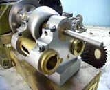
Here is a picture of the Encabulator in its present state. No spurthing bearings yet but there is a small dingle arm sticking out of the panemetric fam. I'm thinking. If manually actuating the dingle arm with my finger produces barescent Skor motion, could this be called a Digital Encabulator?
Jerry

Jerry
- Joined
- Dec 2, 2008
- Messages
- 971
- Reaction score
- 8
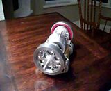
AHA! A digital Encabulator!
tel
Well-Known Member
- Joined
- Feb 8, 2008
- Messages
- 3,293
- Reaction score
- 44
Schooner to Dock to Nick. Been there....Done that
Not usually with a single schooner tho' - several ports do help with the process!
- Joined
- Dec 2, 2008
- Messages
- 971
- Reaction score
- 8
No more silly stuff, I'm actually building an engine here. It will have:
Two double acting cylinders that lie parallel to the output shaft.
There will be no conventional crankshaft or packing gland.
Both pistons will transfer their effort to the output shaft through a single shared actuator arm.
There will be two bearing like devices that prevent movement from side to side.
It will have at least 36 visible socket head cap screws.
There will be at least 2, maybe 4, parts made from common plumbing parts not including the two obvious brass pipes.
If it makes a "Pucketaa...Pucketta...Pucketta" sound I will not be surprised.
If it seems that there are parallels to earlier work undertaken by Chrysler and Rockwell, I can't help it.
I'm not going to do this like a regular "work in progress" thread because, as you can see, it is well underway. I will get a little more detailed from here on out because the build is approaching a point where it is greatly different from previous axial engines that I have shown.
All previous axial engines that I have built are single acting, meaning that force is applied to only one side (end) of the piston, pushing it in one direction with the return force provided by the piston rod. A double acting engine applies force to both ends of the alternately. This is one of the major differences between Internal Combustion engines and steam engines. Most, but not all, successful Internal combustion engines are single acting, while most, but not all, successful steam engines are double acting.
The single acting piston is much more simple. The piston is connected to the Con Rod, which is directly connected to the crank and the only seal of consequence is the piston ring.
The double acting piston connects to the piston rod, which connects to the Con Rod, which connects to the crank. It has piston rings and also a packing gland seal at the rod end of the cylinder. Because of the joint at the piston rod/Con Rod junction, there is also a cross head guide.
In my design the double acting cylinder has a plain head at either end, with no packing gland. There is also no crosshead guide mechanism.
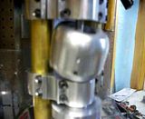
Its getting late, and my eyes are getting droopy but I wanted to post the following pictures of the cylinder and piston.
Jerry
Two double acting cylinders that lie parallel to the output shaft.
There will be no conventional crankshaft or packing gland.
Both pistons will transfer their effort to the output shaft through a single shared actuator arm.
There will be two bearing like devices that prevent movement from side to side.
It will have at least 36 visible socket head cap screws.
There will be at least 2, maybe 4, parts made from common plumbing parts not including the two obvious brass pipes.
If it makes a "Pucketaa...Pucketta...Pucketta" sound I will not be surprised.
If it seems that there are parallels to earlier work undertaken by Chrysler and Rockwell, I can't help it.
I'm not going to do this like a regular "work in progress" thread because, as you can see, it is well underway. I will get a little more detailed from here on out because the build is approaching a point where it is greatly different from previous axial engines that I have shown.
All previous axial engines that I have built are single acting, meaning that force is applied to only one side (end) of the piston, pushing it in one direction with the return force provided by the piston rod. A double acting engine applies force to both ends of the alternately. This is one of the major differences between Internal Combustion engines and steam engines. Most, but not all, successful Internal combustion engines are single acting, while most, but not all, successful steam engines are double acting.
The single acting piston is much more simple. The piston is connected to the Con Rod, which is directly connected to the crank and the only seal of consequence is the piston ring.
The double acting piston connects to the piston rod, which connects to the Con Rod, which connects to the crank. It has piston rings and also a packing gland seal at the rod end of the cylinder. Because of the joint at the piston rod/Con Rod junction, there is also a cross head guide.
In my design the double acting cylinder has a plain head at either end, with no packing gland. There is also no crosshead guide mechanism.
Its getting late, and my eyes are getting droopy but I wanted to post the following pictures of the cylinder and piston.
Jerry
- Joined
- Dec 2, 2008
- Messages
- 971
- Reaction score
- 8
Cast Iron Pipe Plug to Cast Iron Shaft Bearing
Jerry


Jerry
- Joined
- Dec 2, 2008
- Messages
- 971
- Reaction score
- 8
Hi Y'all
This project isn't dead yet. I haven't posted much in the way of progress lately because there hasn't been much, though not for lack of trying. All of the parts have been made at least once and there are no great problems with the maching of the parts. I have discovered one of the great mysteries of 3D design software. It is easy to design an assembly that can't be assembled! A quick example is the use of a fastener in a place where you can't reach with a tool. Another is the case where assembly order is impossible such as two separate steps that must both be completed before the other.
The problem here is connecting the piston rod to the dingle arm after the double headed piston is installed in the cylinder. I know this does'nt make much sense but it's sort of like trying to blow into both ends of a pipe at the same time. I have re-designed and re-assembled the parts so many times that I am afraid that the engine will be worn out before it gets finished.
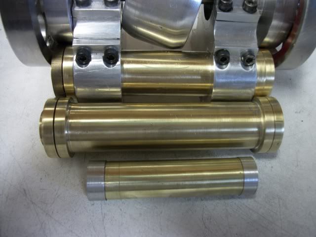
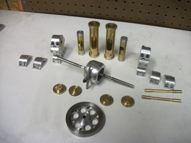
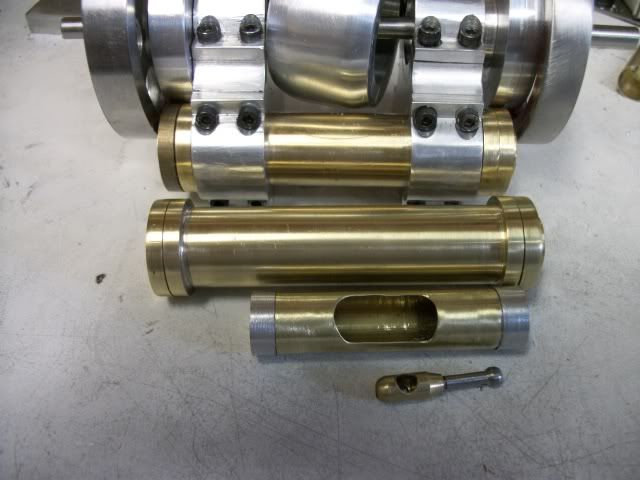
But at last success. I have worked out a technique and assemble order that gets it done! The 1st photo below shows the parts layout. The 2nd shows the piston along side the cylinder. And the video shows the completed assembly with both double pistons functioning in the cylinders. The cyl heads are not installed so you can see the pistons moving. There are two double acting pistons with 90° offset so it will be self staring and there are 4 power stokes per revolution.
Now that this hurdle is past, I can concentrate on the air distribution and control. I may get this thing running yet!
Thanks for watching
Jerry
This project isn't dead yet. I haven't posted much in the way of progress lately because there hasn't been much, though not for lack of trying. All of the parts have been made at least once and there are no great problems with the maching of the parts. I have discovered one of the great mysteries of 3D design software. It is easy to design an assembly that can't be assembled! A quick example is the use of a fastener in a place where you can't reach with a tool. Another is the case where assembly order is impossible such as two separate steps that must both be completed before the other.
The problem here is connecting the piston rod to the dingle arm after the double headed piston is installed in the cylinder. I know this does'nt make much sense but it's sort of like trying to blow into both ends of a pipe at the same time. I have re-designed and re-assembled the parts so many times that I am afraid that the engine will be worn out before it gets finished.
But at last success. I have worked out a technique and assemble order that gets it done! The 1st photo below shows the parts layout. The 2nd shows the piston along side the cylinder. And the video shows the completed assembly with both double pistons functioning in the cylinders. The cyl heads are not installed so you can see the pistons moving. There are two double acting pistons with 90° offset so it will be self staring and there are 4 power stokes per revolution.
Now that this hurdle is past, I can concentrate on the air distribution and control. I may get this thing running yet!
Thanks for watching
Jerry
imagineering
Well-Known Member
- Joined
- Dec 6, 2010
- Messages
- 96
- Reaction score
- 14
.
Rockwell eat your heart out. He's done it - and less than $59,000,000, (I hope).
.
Rockwell eat your heart out. He's done it - and less than $59,000,000, (I hope).
.
- Joined
- Dec 2, 2008
- Messages
- 971
- Reaction score
- 8
imagineering said:.
Rockwell eat your heart out. He's done it - and less than $59,000,000, (I hope).
.
Certainly less than $59,000,000 in cost, even when allowing for the time overrun, but if it were to be sold to the Gov't, there is no relationship between cost and selling price.
Jerry
I've had a great deal of fun following this silly thread - more so now there's a real outcome - well done.
However spare a thought for the members who do not have english as a first language or sense of humour - probably worn out their dictionarys by now.
Si señor derdagos forté lorrez innarro. Demamte lorrez, demistrux, fullacowes, anens, andux !
However spare a thought for the members who do not have english as a first language or sense of humour - probably worn out their dictionarys by now.
Si señor derdagos forté lorrez innarro. Demamte lorrez, demistrux, fullacowes, anens, andux !
- Joined
- Dec 2, 2008
- Messages
- 971
- Reaction score
- 8
Ken I said:Si señor derdagos forté lorrez innarro. Demamte lorrez, demistrux, fullacowes, anens, andux !
Ken
That sent me running for the dictionary but none of them seemed to work. Oh well, as my father used to say, "Non illigitmi carborundum"
Jerry
PS
This has always been a serious build project, by far the most difficult design project I have attempted. I actually began to consider the project several years ago but needed more skill and experience to attempt it.
Jerry,
When I saw it I also ran for the dictionary - nada.
Just read it out loud. Like me you've been had.
"Tauri excretum cerebrum vincit"
Just love your build - line from an old Goon show...
"What is it ?"
"I don't know - it started out as a mangle, but I added a bit here and a bit there and it got completely out of hand."
"Yes but did you notice that just before it fell to bits it raised three feet off the ground."
"Good heavens I've invented the airoplane !"
Ken
- Joined
- Dec 2, 2008
- Messages
- 971
- Reaction score
- 8
ARRRGGGH!
A few days ago I thought I had solved a major problem, but, alas, it was not so. I had indeed solved the assembly problem. Its difficult to explain but it's sort of like being forced to install a wrist pin after the piston is already in the cylinder. In my case, it is assembling a ball joint inside a piston inside the cylinder. I thought I had it worked out and publicly patted myself on the back with a success post.
So, on to other things. I was driving the assembled engine (less heads) with external power to the shaft while working out the valve timing and it was running smoothly but I noticed a rattle sound. Before I could shut it down, one of the ball joints (dingle arm to piston rod) disassembled itself. Nothing damaged, nothing broken. Just fell apart.
This ball joint of my own design, traps the ball end between a fixed seat on one side and an adjustable seat on the other. The adjustable seat is a cup on the end of a #8 brass screw that is the assembly/adjustment point. There are a lot of weak points in this design. There is no room to fit a jam nut on the screw (like on a gibb screw) and no way to tighten it if fitted. There are only about 3 threads of the screw engaged. The screw cannot be torqued down as that would bind the ball joint. Results... screw works loose, ball falls out.
I have considered loctite on the screw but I am afraid it would wick into the ball seat and lock that as well.
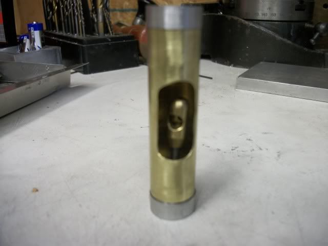
In the picture above, you can see the piston rod inside the double headed piston. The adjusting end is the top end of the rod and It will lean out of the opening enough to insert the ball end of the dingle arm and adjust the screw. Of course the piston must be in the cylinder first!
Another redesign! RATS!!!
Jerry