Elmer' #29 - Mine, all mine

Home Model Engine Machinist Forum

Help Support Home Model Engine Machinist Forum:

This site may earn a commission from merchant affiliate links, including eBay, Amazon, and others.

Sshire

Well-Known Member
Joined
Jun 29, 2011
Messages
936
Reaction score
259
Elmer’s #29 - Mine Engine
Mine, All Mine
Episode 1


And you thought I’d gone into hiding. No such luck. Couldn’t resist starting a new build.

I’ve been looking at this one for a while and the plans have migrated to the top of the pile. After looking at the size (small), I almost did a 2X build but I smacked myself and came to my senses. A larger version isn’t out of the question down the road.

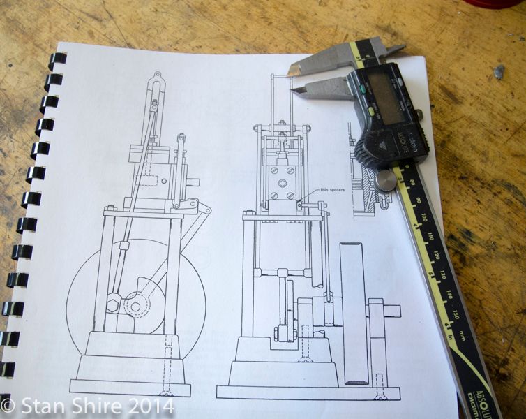
Here is the assembly drawing. This, along with the Pumping Engine, are two of Elmer’s better looking designs.


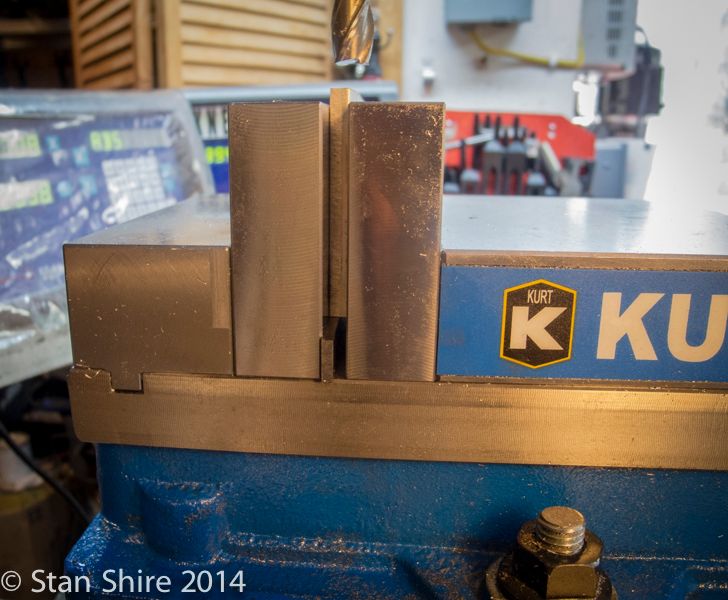
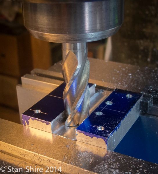
As I began to square up the floor (.125) there was way too much chatter because if was too far above the vise jaws. I swapped the stock Kurt jaws for these 3” MonsterJaws. Problem solved. I know that clamping a part high on tall jaws is not a good idea, but full height clamping works just fine.


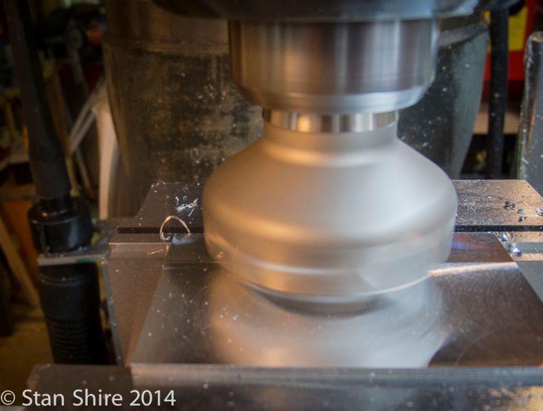
After squaring up and sizing the floor, base and sub-base, the face mill with the super sharp non-ferrous inserts, does its work.


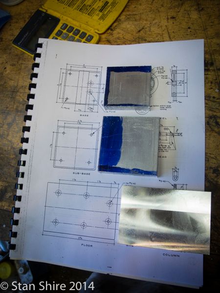
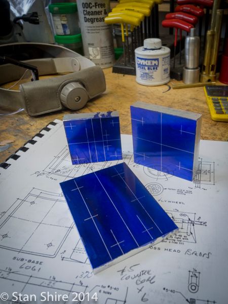
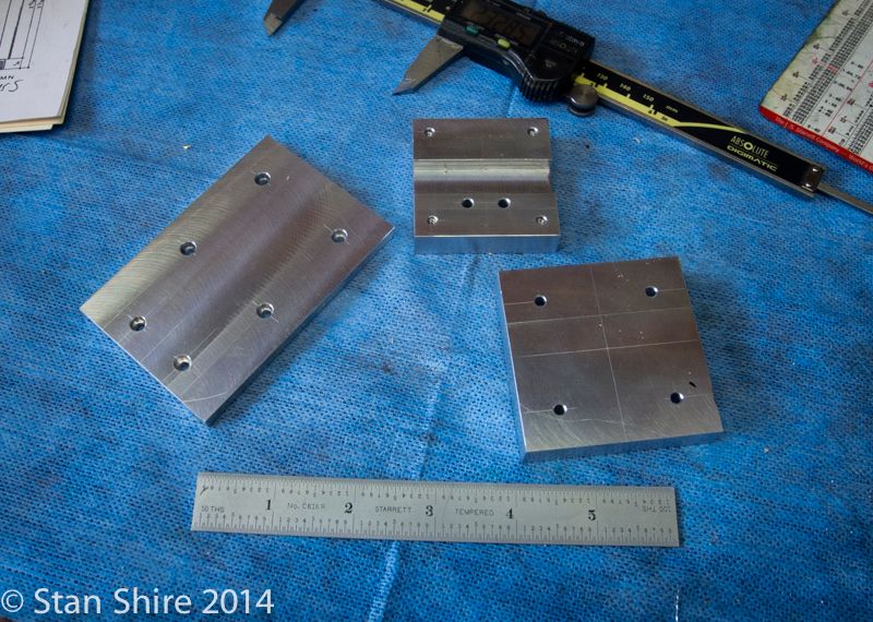
I laid out the three base parts. Even though I’m using the DRO, I like to do a layout as a “double-check.”


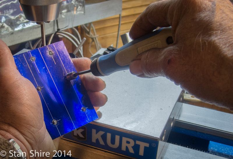
Drilling and deburring. I should have gotten this Noga Rotadrive deburring/chamfering tool long ago. Very quick and no machine setups.


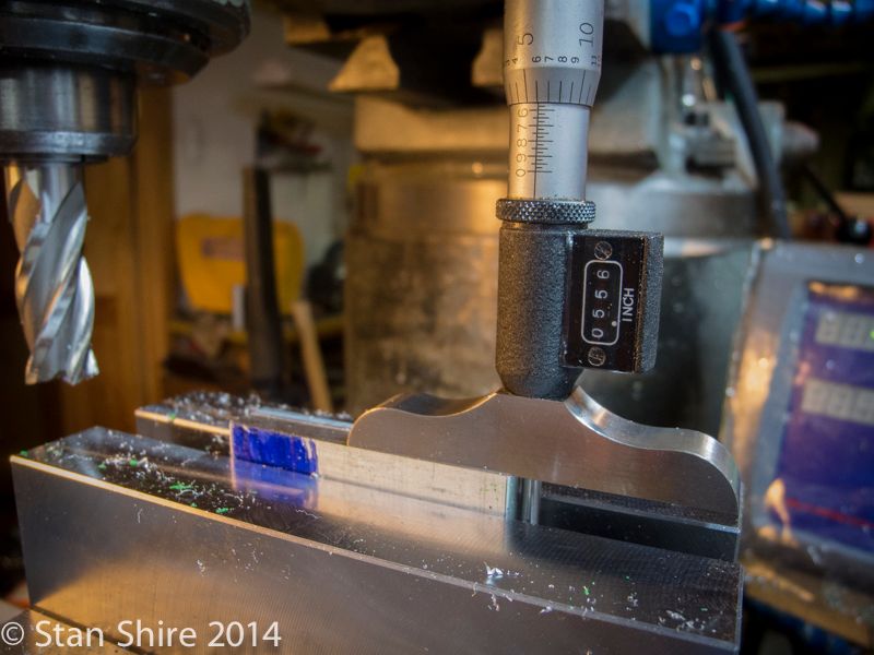
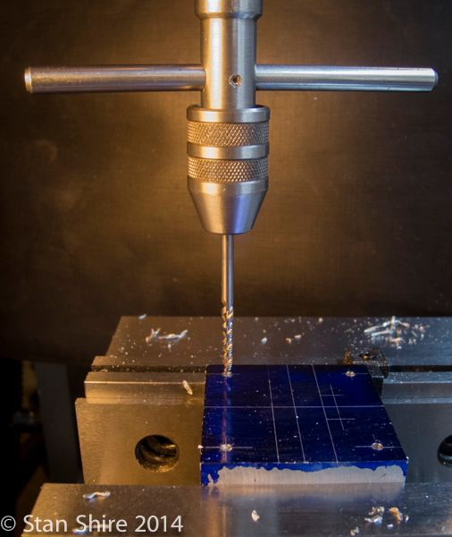
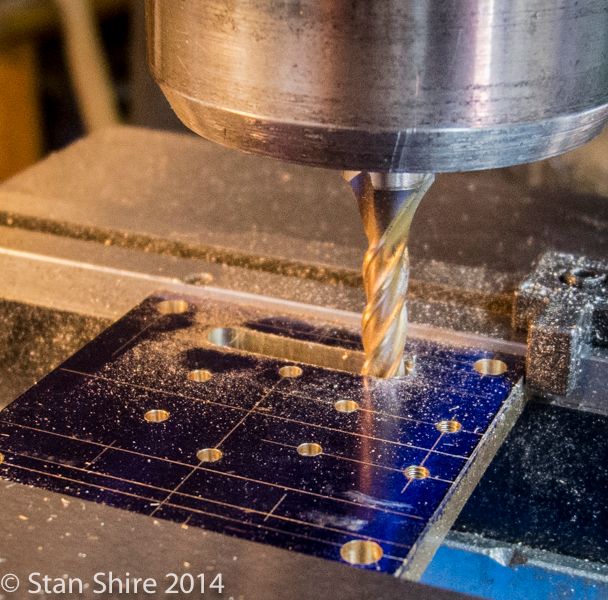
Then drilling, tapping and slot milling.


The bases will have a 5 degree bevel at some point. Right now, I’m keeping them square in case I have to put them back in the vise.
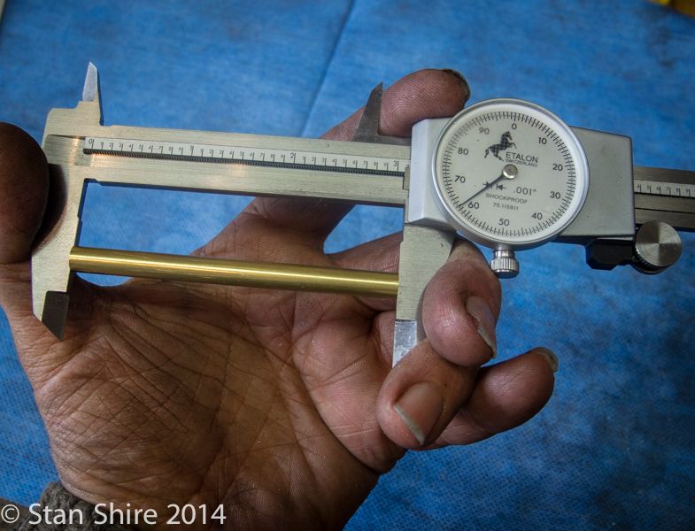
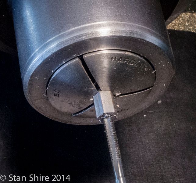


Next are 4 posts. .250” diameter with 5-40 threaded ends. Since these support a plate that has the crosshead guide, it seemed critical to have them at identical lengths. Collet stops on the lathe are close but can have variation in how far the part sticks depending on how tight you crank on the collet thread. I wasn’t that thrilled with the prospect of taking a facing cut, removing the part, measuring and remounting the part.

Of course, the easy way is to take a longer piece, poke it through the collet and spindle bore and part off to length. I don’t have a spider on the end of my spindle, but I did try this, starting the lathe very slowly. By the time I got to about 100 RPM, I thought I noticed the free end beginning to move. Not wanting to bend, or otherwise distort the only .250 brass round in stock. I came up with another way.

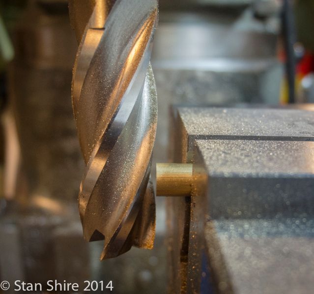
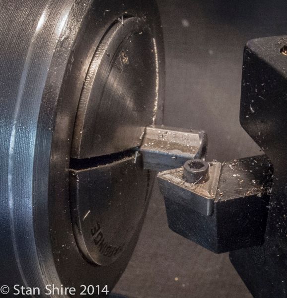
I cut the four pieces about 30 thou long and cleaned up one end at the mill. I did switch to V-jaws.


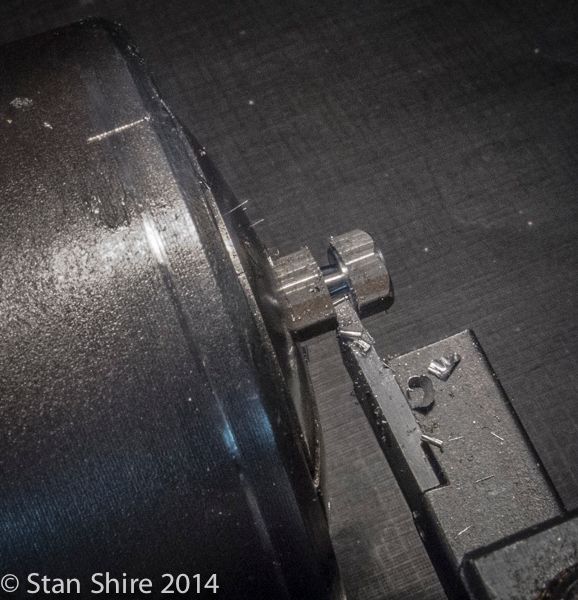
With the rod of the vise stop slid into the v-jaw, I was able to get perfectly repeatable lengths.


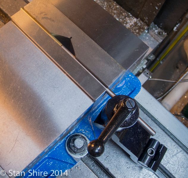
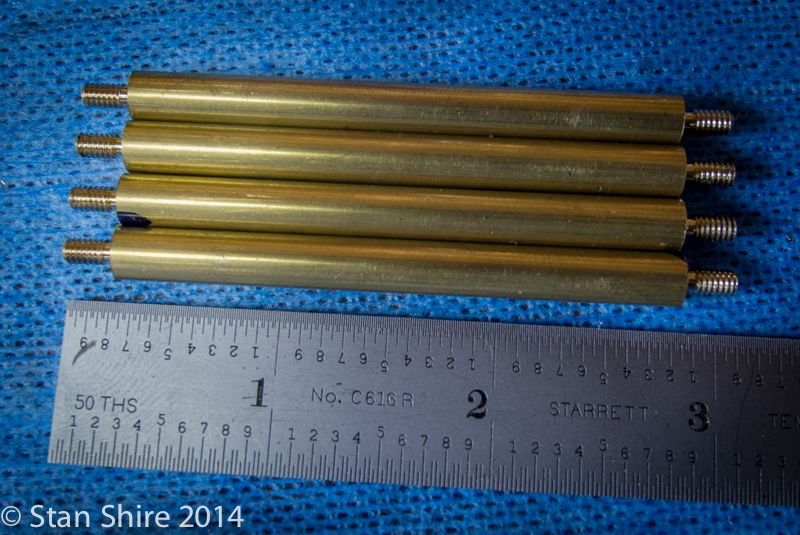
The drawing says 3.0625. Each piece had no more than a half thou variation.


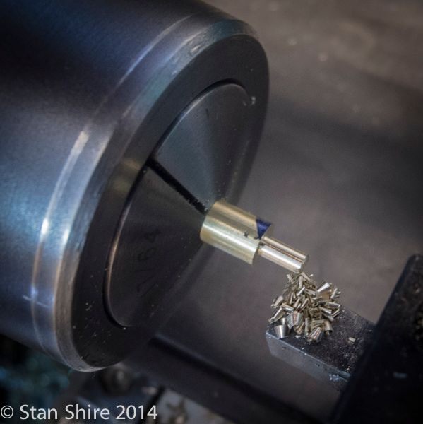
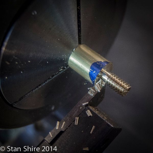
With that done, I used the DRO on the lathe to turn the threaded parts to a length of .250.


With the posts threaded in place, it’s time to move on to the table. I realized I’d need 5-40 nuts to half the table so those came first.

.250” 12L14 Hex bar, drilled and tapped.


Corners knocked off


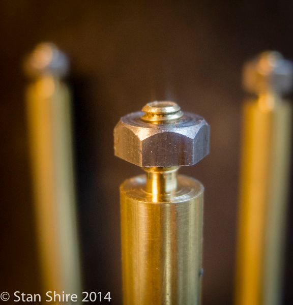
Parted off. If you look at the back of the nut, you can see that I turned a small boss. Help! Does this feature have a name?


I went a bit too far on the corners. I think the arc is supposed to meet the flat. I need to use my 10X magnifier when I remake them. Any nut tips would be appreciated.


Now for the table. All laid out and ready for the mill.


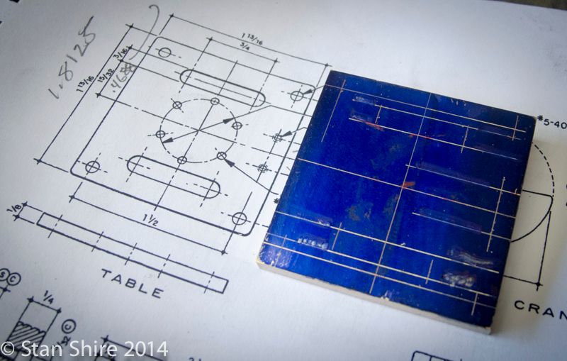
Everything is referenced from the center of the table.


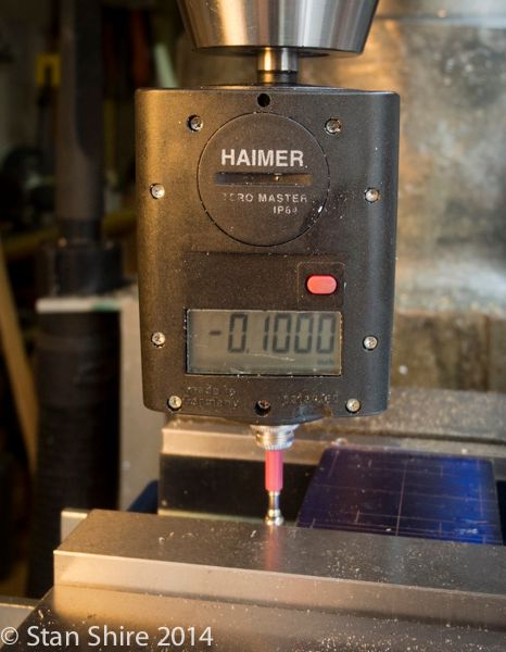
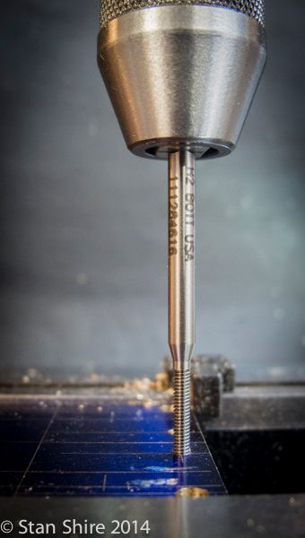
2-56 form tap. This is a Balax. I only say that because they were the only form tap manufacturer whose tech support guy would talk to me after finding out that I wasn’t General Motors or NASA. He was fascinated when I mentioned small engines and spent a long time telling me more than anyone needs to know about form taps. I’m a committed Balax purchaser and quite sure that the 5 form taps I’ve bought this year made a significant difference to their bottom line.


Bolt hole circle


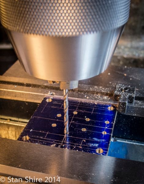
Slots milled and that finished this part.


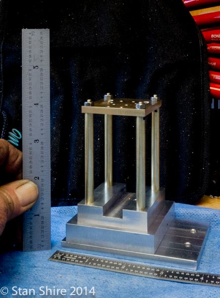
So, here we are after two days in the shop. More to come.

 
Im so jealous of the time you guys get to spend in the shop...Very nice work as all ways Stan. Think youll finish before cabin fever??
 
It's an addiction. At least it's legal.

It's called "retired". The payoff for working.


Sent from my iPhone using Model Engines
 
Stan. You are an animal. Lol. This engine is high on my list but have a few other projects to complete

Dave
 
Dave
Did u ever get the collet closer on the SB working?
 
Elmer’s #29 - Mine Engine
Mine, All Mine
Episode 2


Next up are the bearing towers. I used the same technique for the arch top as on the Mill Engine build. First, step drilling and then boring a hole.


Then, side milling the top. The high helix end mill leaves a very sharp corner.


The insert is a press fit. I put a spacer under the insert to have it above the surface. Purely decorative.


Then face milling the back side to bring it level with the insert.


Drilled and reamed for the ball bearing. The hole is smaller than the bearing O.D. and will be enlarged by line drilling and reaming through both bearing towers when they are bolted in place.


The fixture plate is getting a lot of use. The part is squared up in preparation for making the side curves.


As on the Mill Engine build, I used the boring head to machine the curve.


Moving over on the Y-axis the same distance from center and more boring.


A curved file in Oliver to smooth things out and blend the part.


I’ve decided to remove the “ears” at the tops of the curves. A bit too Asian for this engine.
I’ll get to that later.


The small bearing tower is built in the same way. This will probably stay square.


Two more parts added in place.


Crosshead Guides

Elmer has an odd piece at the top of the crosshead guides to hold a pin which maintains the spacing between the two guides. I’ve been looking at it and liking it less and less. I’ve devised another, I think more elegant, solution. When screwing with Elmer’s designs, I try to maintain the dimensions and work around those. The guides have a milled slot for the crosshead.


Nothing fancy here.


The two guides fit in slots in a bottom plate. Faced, turned and drilled.


Then moving the collet to the mill for the bolt hole circle.


Then the .0625” slots are milled. For slots with a depth less than .125”, I’ve become a big fan of stubby end mills.


Back to the lathe to be parted off and done.


Test fit before soldering the guides in the plate.


I wanted to be sure the guides were parallel to each other and perfectly perpendicular to the base. This seems like binding waiting to happen if they are not. A fixture seemed like the answer. The crosshead guides slide into the slots and the block is as square as I could make it without a surface grinder.


So, with the smallest Kant Twist clamp holding everything in place, I soldered it together. Uneventful.


A few solder bumps to be milled off and the ends trued.The fixture was also useful for clamping the part in the vise.


Next, a .50” brass round had a few steps milled on one end.


Then to the mill for two .0625” slots.


Test fit.


Steps were milled at the other end with a parting tool and the part was cleaned up and polished.


The assembled crosshead guide.


Watch for the next episode when this piece of square bar gets clocked in the 4-jaw chuck and metamorphoses into a cylinder.

 
Dang! I just sneezed and looked again and the engine is about 25% complete. I think I would have just started my second cup of coffee while looking over the plans.. impressive work Stan.
 
That's the problem with you guys who have to work for a living. I'm amazed that, with a job, any engines get done.
 
Stan

Another work of art in the making, and as always superbly documented.

I'm not building Elmer's engines at present (distracted by a Minnie traction engine), but I'm still watching those who are!

Kind regards

Geoff at Inky Engines
 
Thanks, Geoff. Much appreciated.
I'll keep working at approaching the quality level of your engines.
 
Elmer’s #29 - Mine Engine
Mine, All Mine
Episode 3

Cylinder


The cylinder starts as a 6061 1” square bar. Mounted up the 4-jaw and indicated the bar.


The cylinder ends were rounded and then step drilled and reamed .500”


Parted off for a trip to the mill.


I centered the bore with the eBay Blake in preparation for drilling a 6-hole bolt circle at each end.


The bolt holes were drilled and tapped for 2-56 screws (on the bottom) and studs (on the top)
I love how the spiral flute tap pulls the chips up and out of the hole.


Next, the flats are milled down .1875” on three sides. The fourth side isn’t reduced in depth. The ports will be drilled on that side and the steam chest mounts there.


Then, with the cylinder resting on a rod, it’s turn and mill, turn and mill. The more facets you do, the easier it is to round the part later.


I let Oliver fettle the facets off, followed by various grits of emory.


And ended up with another part.


Tomorrow, the heads.
 
You bet! Spiral point for thru holes (pushes the chips ahead of the tap) and spiral flute ( pulls the chip out of blind holes)
My favorites though are form taps. No chip at all. The tap drill size is a bit larger but they cut threads with no backing out, no binding. Clean as a whistle. You really have to work to break one.
 
Hmm, more to taps than meets the eye. Or more to taps than I know about...In any case im learning some cool new stuff. Thanks Stan!
 
Elmer’s #29 - Mine Engine
Mine, All Mine
Episode 4


Between Cabin Fever fast approaching, working on the mine engine, trying to get the summer furniture out of the basement between snow and rain days, installing a Sunsetter awning, etc. etc, etc., it seems that I’ve neglected posting this build. Time to play catch-up.

A rectangle of brass, centered in the 4-jaw for the steam chest. If I had known 2 years ago that Elmer used the same steam chest, valve, plates, nut and rod, I’d have made a bunch as each was setup.


This will be a composite steam chest. The closed end which guides the valve rod will be turned and the open, threaded end will be an insert.


Turned to diameter and a round-over bit to finish. Saves making a form tool.


Then, over to the mill. The corners are drilled.


Everything that isn’t a steam chest is removed.


The threaded insert for the valve rod and nut. This was Loctited in place.


Clearance holes for mounting.


The cylinder has more milling and drilling to be done. After indicating it to level…


The intake and exhaust ports were finished.


Mounting the cylinder in a 5C collet and collet block, the port face was made parallel to the collet block.


Then the block was set at an angle for drilling the connecting ports. I’ve never had Elmer’s suggested drilling angle work for me. The scribe lines are the port locations. I set the drill bit in front of the cylinder and align it with my scribe lines. Works every time.


And that finishes the cylinder.


Turning the piston and the oil grooves,


Another part finished.


The crank starts as a 360 brass round turned to diameter. It was just a bit bigger than the largest 5C collet, so the 4 jaw was mounted again.


The center boss was turned, drilled and reamed.


Onto the Bridgeport with a ball end mill.


The shaft was a nice press fit then on to Oliver for some rounding.


Preliminary polishing. I find it easier to see the areas that need extra attention this way.


Next, the eccentric. Centered and then offset by .050”


With the eccentric completed, I can work to a good fit for the eccentric strap.


The ring is parted off and a slot is milled.


Then the strap gets a concave cut to match the I.D. of the ring.


I thought I’d go into some detail with my soldering procedure, as this was one area that gave me problems when I started building engines. First, the parts must be very clean. I sand to 400 grit (220 would be just fine) then a dip in acetone. The parts come out and go onto a clean paper towel.


Flux applied. I try to keep it in a small area. Makes cleanup easier later. The other thing here is a solid setup. Nothing worse than getting the solder to flow nicely and have the parts move.


The solder also gets a cleaning with 400 grit to remove the oxidized silver then cut into tiny bits.


Heat applied until solder flows.


Removing the flux with citric acid. I bought a pound (about a lifetime supply.) I'm not very fussy with this. I do a fairly saturated solution in hot water and drop the part in. A few minutes and all of the black stuff wipes off.


Now, here is where you get your money’s worth for reading this post. The secret to eliminating the pink staining (it’s actually copper which has migrated to the surface from heating)


Nothing exotic here. Drugstore and supermarket items. The secret formula is on the vinegar bottle.


Set your timer for 15 minutes and check after 10 minutes. If you leave the part in way too long, the solution begins to eat the brass.


It will begin to gather bubbles.


No more pink.


Lining up the strap for drilling the end. I put the eccentric in place to keep the vise from crushing the ring. I believe it was in James Harvey’s Machine Shop Secrets book that said “Never clamp on air”


Two pack nuts needed. Hex brass stock. Turned, drilled, reamed and threaded.


I though about this for days. Finally decided to build it up.


Two are needed, so I made them on one piece of stock to be cut in half later and then rounded over.


I turned the bosses from round stock. The pins have grooves at the ends for 1/16” e-clips.


The rocker bearing was straight milling and drilling.


Just milling to split the line.


Just to pretty the part, some rounding.


Then drilled and reamed for a shaft.


That goes into the “to be fettled and polished” box


Two links in 1/16” brass. Round ends. Oliver is getting a workout on this build.


Some polishing with a brass brush on the rockers. Is that the cutest Kant-Twist ever? Ooooh. Look. A package from PM Research.


Then three pieces to connect other pieces. Two shown here. All different. It’s way past time for the fine Scottish produce and I don’t remember what these parts are called and don’t feel like running down to the shop to look at the plans and see what the damn things are called. Look it up.


Con rod top section ready for soldering.

 
Casting Couch

I was going to put this in a separate post (and probably will) but since it will be a part for this engine, here it is.

I was sitting on the couch, thinking about some different treatments for the steam chest cover on Elmer's Mine engine.

A clear cover would allow the valve movement to be seen. Scratch that. Watching a tiny bit of brass move to and fro just isn't THAT exciting.
Or
An engraved cover with some sort of design. Scratch that. My total experience with engraving is a witness mark to align a cylinder and the head. The line wasn't even straight.
Or.......
I've always admired the cast covers on the Stuart Engines. Big letter "S"
Scratch that. My total experience with casting was watching some guys at Cabin Fever doing a casting demo in the parking lot.
But
Until a bit over two years ago, I knew that Bridgeport was a town in Connecticut and, since I grew up in a steel town, I knew that a mill was a place where a lot of my friend's dads worked.*
I figured out the lathe and the mill. I think I can figure out small scale casting.*

A silversmith friend gave me a kilo of something called "Delft Clay." some sort of very fine detail casting sand or clay or ??? that silver and goldsmiths use.


I turned two interlocking pieces of *2" aluminum tube for a flask. I got a "melting thingee" (crucible?) on line.


*Made a pattern with aluminum (actually made a few) and SuperGlued the Elmer's engine number (29 for the Mine Engine) in the recess.


Watched some YouTube about casting with Delft Clay then pillaged the small scrap box for bits of brass. I rearranged the firebrick that I use for my soldering area to retain more heat and cranked up the Turbo Torch (air/propane). The Turbo Torch just got the brass hot enough to begin to melt and no further. Switching to the oxy-acetylene.


The Delft Clay was packed into the bottom of the flask and the pattern was pressed in and carefully removed.*Not carefully enough as you can see here. Repacked the clay and pressed the mould in.


Packed the top half and cut an opening for pouring and some outlets


Small holes and channels for air to escape and put the halves together. I crossed my fingers, *put on welding gloves, a leather apron (to look like I had a clue) and full face shield.


First casting was fairly crappy. Made a new (deeper ) mould. Much better.


I’m making a larger mould.(by .5”) I realized that having more material will make machining the edges easier. Stay tuned.
 
Well Done Stan!!

You are doing well with the wee engine, and your casting is coming along just fine.

Cheers,

Tom
 
Back
Top