Electronic Dividing Head using the Arduino

Home Model Engine Machinist Forum

Help Support Home Model Engine Machinist Forum:

This site may earn a commission from merchant affiliate links, including eBay, Amazon, and others.
Hi RodW
Wasn't there a problem encountered with counting such large numbers of pulses? something about "rounding" number of steps or pulses ?
Perhaps this was only in Chuck's original sketch.

xpylonracer

I think in Chuck's original code, he may have used floating point maths which can result in rounding errors. I don't use floating point maths. Instead I reduce all angles to seconds of a degree so 360 x 60 x 60 = 1,296,000 divisions in a circle. That way rounding results in +- 1 second of a degree.

Accuracy is dictated by the number of steps your stepper takes and your final drive ratios. Microstepping increase resolution to a certain extend but if you are microstepping (I can use 40 x microstepping with LinuxCNC, or 8000 steps per rev) but that does not mean that I can achieve accuracy of 360/8000 of a degree. Do your own maths to determine what angle you can do per step.

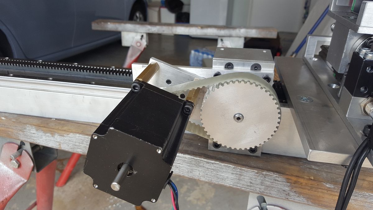
I would look carefully at the gearboxes you are considering, unless you spend a few hundred $, the backlash is around 1.5 degrees. You will get less backlash with a timing belt and there are plenty adding them to rotary tables. Heres a 3:1 I've built for a pinion drive.
20161023_082859_zpsulsnatze.jpg
 
I will try to understand the code in due course, but I'm not sure I will be able to... I should explain that I had a minor stroke earlier this year and, while I'm ok, I find it difficult learning new things - that and I'm not as young as I could be
Sorry for the thread drift as I'm not building an Arduino dividing head (yet) but I do read everything that Chuck writes.:thumbup:

Duncan I'd say you're doing great with your stroke recovery and this sort of mental/physical exercise is just what the doctor ordered. I too suffered a stroke just over a year ago and am so fortunate to get back to where I was before it happened other than subtle changes in memory and occasional bouts of tongue-tiedness & frustrating clumsiness. I'll take it though as a year ago this post would have taken at least an hour to finish and brushing my teeth consisted of using two hands to hold the brush still and nodding my head up & down clumsily against it. I almost totally lost the use of my right arm & right leg and talked like a drunk.

Best of luck to you in your recovery and keep on doing what you're doing in the shop; it's the best therapy!:thumbup:
 
Duncan,

The accuracy depends on the number of motor steps it takes your spindle to go one full revolution, regardless of your calculating method. My code does use floating point, but because of the way I recalculate each spindle position from the origin, the errors even out. It's never off by more than +/- half a step relative to the origin. See the attached spread sheet which shows the stepper positioning my software would provide.

If you have 4000 steps and want 127 gear teeth, you'd ideally want 31.496 steps per division. My code would round down to 31 steps for the first tooth, then round up to 63 steps (from orgin) for the second tooth, etc. This ensures that the error is never more than +/- 1/2 step or 1/8000th of a turn, in your case, per tooth relative to the origin. For example, if your gear is 3 inches diameter which is about 9.5 inches circumference, the angular displacement of a tooth would be no more than .00118 inches. I would consider this acceptable, but others may differ depending on the application.

Half stepping would double your accuracy. Quarter stepping would quadruple your accuracy, etc. I believe the A4988 stepper driver can go up to 16th step microstepping through the use of jumpers. These are well documented on the internet and I can help if you want to go this route.

Chuck

View attachment StepperMath.xls
 
Last edited:
Once again Chuck, thank you!

I have had a change of mind. I was going to make a dividing head like yours, but for simplicity, I have decided to convert my Tom Senior dividing head - 40:1 ratio.

I had a good look at it yesterday and it's very easy to convert. In fact, I have done most of the conversion work today. I just need to make the coupling between stepper motor and the dividing head shaft... This means I will have 8000 steps per revolution of the dividing head, or more if I use micro-stepping... Any recommendation for micro-stepping, or not to?

The 127 tooth gear I want to cut is 18DP, so will be just over 7" in diameter, which was a factor for deciding to use my existing dividing head as it will take a 7.5" blank for cutting.

Thanks for the explanation and spreadsheet for stepper positioning, I will look at the code and hopefully will be able to make more sense of it, with the spreadsheet info...

On that subject, where do I find the latest version of the code? I have found two different versions, but do not know which is the most current.

I received my Arduino and LCD Shield today, so am very keen to try them out, but I'm still waiting for the driver board.... :(

One final question, I have been given a stepper motor, part number HY 200 2220 100. This is an 8 lead motor rated at 1A current, voltage up to 75V, with holding torque of 69Ncm (98 oz/in, 9.99kg/cm) in bipolar mode. With the 40:1 worm drive, I'm confident the holding torque will be more than sufficient, but I'm not sure the motor will be powerful enough to turn the head... I know I can try it and find out, but I'm wondering if you could offer an opinion?

Thanks again!


Dickeybird, Thanks for your kind words. Fortunately my stroke just left the left side numb for a day or two, but I am left with a permament lack of sensation on the left side of my head. I too have notice a subtle change in memory and lose words sometimes. And, I understand the clumsiness, my balance is very poor now...

I will not give in to it though and am doing as much as I possibly can, but am aware I have limitations...

Good luck!

Duncan
 
Duncan, I don't really think microstepping is necessary. You certainly don't need it for accuracy.

I think the version of software on this website is the newest that has the option for two different devices. I have a newer version that is only designed for a single device, dividing head or rotary table.

I don't believe the stepper motor you've described is beefy enough to spin the dividing head reliably. However, it wouldn't hurt to try it. The A4988 stepper driver will handle current up to about 2 amps with a heat sink, although that's pushing it. There is an adjustment available on the A4988 which lets you limit the current. Also, I believe the A4988 is rated up to 35 volts, although, again, that would be pushing it.

Chuck
 
That was fun - Wanted to see your [cfellows] program in action, well at least as far as my little cigar box will allow. Had to do a little change over to use momentary switched in lieu of the voltage divider sainsmart uses. Bumped the read button delay up to 250 from 200 so I didn't get a double position move.

Once I got it, l Liked that passing of the direction var e.g. step (1); you did - So I learned something new . . . .

DSCF0119_zpsrmycouns.jpg
 
That's a tidy arrangement you have there, Foozer. I like it!

Using functions with passed variables is a good way to keep your software modular and easier to follow. In my early days of programming (many, many years ago), programming was all done in pretty much linear fashion so programs got complicated quickly. Many a time I spent the first half of my work day trying to figure out my code from the day before!

Chuck
 
This stuff looks very cool and having built my own 3d printer I'm pretty familiar with steppers, arduino etc.
Now I just need to justify in my head the NZD400-500 for the rotating table to connect it all up to. :hDe:
 
I have read this article with interest. I now have my Arduino Uno, Sainsmart display and stepper driver on order.

I have not order the motor yet. When looking at motors both NEMA 17 & 24 I see they have a torque rating. I plan to use my dividing head for doing gears and it will be similar to the one Chuck made as seen in post 18. Can someone give me a idea on what the minimum torq spec should be.

I also looked at the larger buttons someone recommended in this link. http://yourduino.com/sunshop//index.php?l=product_detail&p=334 Can I just hook these up and us either the ones on the display or these without doing any different coding?

Thanks for your help and I am sure I will have more questions in the future as this project and my learning progress.

I would go with a NEMA 23. I used one I salvaged so am not sure the specs but it was margjnal at 19 volts but was fine at 48 volts. I did a lot of my development with a nema 17 and I think it would be a bit light on for torque. I bought a 269 Oz one which I would have used if it was required.

As far as the buttons go, you have 3 options.

1. Solder wires on either side of the switches in the board.
2. Check the wiring specs for the display I used and just use some resistors to replicate the keyboard buttons externally so you don't have to modify the display shield.
3. Use buttons with built inresistors and iff different, modify the code to suit the different resistor values.

Persinally I'd just use separate switches and add the correct resistor values to replicate the onboard buttons.
 
The values in the sample sketch provided with the larger buttons are the same values as the smaller buttons, so first guess is that you could use a plain 20X2 or 20X4 LCD for display and the larger buttons for input . . .
 
Hi, new here, and frankly I'm not even a model engineer, but the topic caught my attention a while ago.

I'm having a strange problem with this setup. I'm using the Liming 2.3 code available at the Digital Machinist website with an Arduino Uno clone. I've wired my setup just like Liming does here, except that I don't have temperature sensors at all. I have a 12 tooth HTD gear at the Nema 23 stepper motor and a 72 tooth gear at the spindle giving me a 6:1 gear ratio. I'm using a generic Chinese TB6560 at 24V 2A at the moment. I have tried other current settings, but it doesn't seem to make a difference.

Everything works like a charm... except that I'm not getting a full 360° rotation, but ever so slightly less. So if I choose, say a 10 step program, and at each stop I poke a mark on the workpiece with a sharp point, everything looks OK at first glance until I arrive back at the starting point. The needle doesn't align with the original hole, but is just a little bit off. If I go through the program again, the same happens with all the holes. If I keep repeating this over and over again, I'll end up with a line of dots. It's not far off, at about 40mm diameter it's only maybe 0.1-0.2mm off.

I've tried several things so far. I've changed the microstepping from 1 to 16 and it doesn't seem to change the situation. I've also changed the code so that the motors step number is 199 instead of 200 and with this setting it's way off, much more than it is when the all the numbers are correct. I've also tried different decay settings on the stepper driver. Some of them don't work at all and the motor keeps juddering randomly and only 0% setting is completely calm and quiet.

Within the code I've tried changing the pulse width, SpeedDelayIncrement and ADSettleTime settings without any significant change.

Any ideas what could be off? Am I missing something?
 
Last edited:
As I see it, either it's a ratio problem, be it physical or within the program, or your setup is losing steps somewhere. To try and diagnose, could you set it to turn some decent amount in one direction, then the same amount back again and cycle that a few times? (Not sure if this is possible with the code you're using) If you can do this and it keeps hitting the same spots (the first two points may be slightly off to the rest as backlash is taken up, but subsequent points should be 'spot-on' to each other) then it's some sort of ratio error. If the spots keep shifting then it has to be a matter of losing steps.

Sorry I can't be more helpful but hopefully you can at least narrow down the possible errors.
 
I've tried this setup with another stepper motor and two other Chinese stepper drivers. I had other issues with those setups (namely just random juddering), but as I recall it I didn't have an alignment issue.

I'm thinking the stepper driver is doing something funky, and I have ordered a Leadshine DM442 driver just in case.

It is possible to move back and forth with the Liming code. It has several different programs to choose from, and really the step program is the one I'll ever need with this setup. I'll give it a go and see what happens.
 
OK, so I tried the moving back and forth using a 2 step program, so 180° per step, and I also made a few more attempts in just going through a 22 step program. It seems I am losing random steps. The error seems more consistent when I'm moving forward only and more random when I'm forward and then back again. Sometimes the needle point aligns perfectly and sometimes it doesn't. During the test I was using 16 microsteps.

This time the diameter was about 68mm and the error seems to be more or less 0.2mm in the 22 step program moving forward only.

Seems really weird to me. I guess my best bet is to just wait for the new stepper driver and trying if it makes a difference. I'm also tempted to buy a genuine Arduino Uno board, as I have had some pretty random issues with these Chinese clone boards in other projects.

But still, if anyone has any ideas what could be wrong, all suggestions are welcome.
 
I think you are missing steps, probably when starting up when there is insufficient power to overcome the initial inertia. Also, 24 volt is not high enough (I first started with a 19v power supply). I would strongly recommend you order a 48 volt power supply to go with your new driver. I think doubling the voltage quadruples the torque or something like that.

I had similar issues, I bought a larger stepper motor but never bothered to install it because all problems disappeared when I increased the voltage to 48V so I never upgraded the motor.

Also, a good motion controller should ramp up to speed and then ramp down at the end of the move to prevent overshoot. If you find a spec sheet for your motor, it should show the RPM for max torque. You need to start in this range and ramp up to speed. There is another Arduino based controller on this forum that deals with all of that. I wrote it so its probably not appropriate for me to link to it on this thread.
 
Last Good First Bad - - Take it your system is belt driven - Mayhaps disconnect the belt and cycle the motor, say one revolution at a time, see if the software cycles the motor itself now free of any drag properly . . Belt too tight will lose steps . . .
 
I think you are missing steps, probably when starting up when there is insufficient power to overcome the initial inertia. Also, 24 volt is not high enough (I first started with a 19v power supply). I would strongly recommend you order a 48 volt power supply to go with your new driver. I think doubling the voltage quadruples the torque or something like that.

I had similar issues, I bought a larger stepper motor but never bothered to install it because all problems disappeared when I increased the voltage to 48V so I never upgraded the motor.

Also, a good motion controller should ramp up to speed and then ramp down at the end of the move to prevent overshoot. If you find a spec sheet for your motor, it should show the RPM for max torque. You need to start in this range and ramp up to speed. There is another Arduino based controller on this forum that deals with all of that. I wrote it so its probably not appropriate for me to link to it on this thread.

I will have a look at your code. I have enough parts to put together another unit so I can compare them.

I do have a 36V 8A PSU and I tried using that instead. It made absolutely no difference. I didn't change anything else. Unfortunately the new stepper driver only supports 40V, but I do have a 48v power supply coming in as well. I do have a stepper driver that supports 50V but as I recall it, it has some juddering issues.

Last Good First Bad - - Take it your system is belt driven - Mayhaps disconnect the belt and cycle the motor, say one revolution at a time, see if the software cycles the motor itself now free of any drag properly . . Belt too tight will lose steps . . .

My belt tensioner is completely manual, so I get to choose the tension. It doesn't seem to make a difference either, as I've never tensioned the belt incredibly hard. The motor bracket is one of those flimsy ones made of sheet metal, so if the belt is tensioned too much, the bracket will bend.
 
So assuming you are not loosing steps, and your gearing parameters are accurate, I would try turning the dividing head one revolution and measure the error. Then (and you may need to modify your script to do this), rotate the dividing head 10 turns and measure the error. if one reading is 10x the other, then you have a calibration issue. If the error is the same then you have a backlash issue. If its somewhere in between, I have no idea, could be electrical noise.

Also, if you have one of these slotted joiners, they can be a source of backlash. You could have a pulley moving on the shaft

DSC_5257_zps997aeeae.jpg


Your timing belt needs to be tight to eliminate backlash.
 
"Juttering" AKA Fubar - Tried a GRBL compatibly shield on my little test platform and got a case of what could be described as 'Jutter' - Motors erratic, run a bit then do a dut,dut, dut, even change direction on their own. Tried an EZDriver - all was good - reconnected the shield and spotted a little glow - Bad solder spot Y Axis motor pins . . . Pulled the driver all is good - - Moral of the story - Just cause a controller seems to work, doesn't mean it is without fault . . .

DSCF0161_zpsiuvtt4cd.jpg
 
Back
Top