Effective muffler for a two-stroke model aeroplane engine.

Home Model Engine Machinist Forum

Help Support Home Model Engine Machinist Forum:

This site may earn a commission from merchant affiliate links, including eBay, Amazon, and others.
Cannuckistan = "country of Cannucks" = Another colony of the Brits....
Since G.Washington and his tea party mates declared independence from Brittany (read the declaration?), many Colonies have tried to become independent from the UK... but sensible ones have kept their links...
K2
(Snort) Sensible - - - dunno about that - - - a very expensive set of rubber stamps it would seem to me.
Lots of pomp and circumstance and little practical good (except for dumping more $$$ down a drain - - - if only someone piped such a load to me - - - if only for a month!!).
 
We Brits Love the Pomp and Circumstance! And the biggest worldwide audience for our Royals is the "new Country" as we call the US of A. More Royal followers there than total population of the UK! Can't be a bad thing!
K2 (A Royalist - in case you hadn't noticed?).
 
I think there is something awry here?
Yes you should use degrees K...
But from PV=RT, then T is proportional to the product of P AND V. I think you have only changed P? (or V?) in your calculations? - Or maybe I misunderstand...?.
So maybe you should be using T2 = T1 x (P2 x V2) / (P1 x V1):
With "P" and "T" as Absolute values, not "gauge" & "deg. C".
But best check with a mathematician, as I get dyslexia (deslyxia?) with this algebra nowadays!
;)
K2
Aha! - I thought that my maths was looking a bit dodgy!.
Maybe I would have to break out my old textbooks.
I always thought P was proportional only to change in V, and T would take care of itself.
You need to get into adiabatic expansion and specific heats to work out how all of there are related.
However, I don't need to know these values precisely, as the muffler will be made without any serious calculations.

There is somewhat less energy involved than with an actual high powered rifle discharge.

You don't want to be too close to the muzzle plane when those go off!
Maybe the supersonic projectile velocity makes the shockwave a bit more vicious!

A .22 lr is not too bad, and comparable for noise output, for each shockwave, anyway.
 
Kevork

Is the engine shown your own design ? looks like it is for tethered car model, very strong looking design, I like how you design the starter flywheel via the crankpin.

Xpylonracer
 
Hi Owen.
I can certainly say that most of the factory lads were deaf from earlier designs of circuit breaker being operated (to prove settings and mechanical function) indoors... A whistle would blow, everyone would put fingers in ears and open their mouths while a 135dBA "Boom" echoed around the large factory building! When they heard my silenced 'breaker, they thought it had malfunctioned! - "Those were the days!"
K2
 
Very interesting discussion, I follow,
I also built 2 exhausts, they work very well.
 

Attachments

  • S1036264.JPG
    S1036264.JPG
    173.5 KB · Views: 62
  • CANISTER 3.pdf
    22.5 KB · Views: 87
  • 001.JPG
    001.JPG
    184.2 KB · Views: 73
  • 002.jpg
    002.jpg
    274.9 KB · Views: 68
Here is an actual "race" 50cc with a pipe, which looks quite small, but it is designed to run at 17500 rpm.
a 6000-7000 rpm pipe would be much longer.
He has made an odd choice to run a variator transmission, but I suppose a proper race bike gearbox would be very expensive!
this is from You Tube "2-Stroke Stuffing".
my current mufflers look a lot like 002 in the previous post, from the outside.
They are better than the OEM small cans, but still not all that good.

Is 001 related to 002?
Do the two rings with holes fit over the raised parts of the tube?
The parts are nicely machined.
 

Attachments

  • engine and pipe.jpg
    engine and pipe.jpg
    35.5 KB · Views: 69
Last edited:
PDF, 001 and 002 is the same muffler,
yes the 2 perforated discs fit the raised part
 
PDF, 001 and 002 is the same muffler,
yes the 2 perforated discs fit the raised part
The scheme I have in mind will be much more restricted than this . Two additional 120 degree v baffles, one of the two plates with many much smaller holes,
and a fairly long 430mm tailpipe, running inside the can, and sticking out towards the front.

I think the initial blowdown out to 600 ccs will be fairly unimpeded,
but possibly the final exhausting process will be slower.

Extractor flow at 5/8" (14mm ID) may be enough to get below atmospheric, though.
It will be interesting to see how it works. A bigger overall volume at 1.2 litres.

I see the pictured muffler has a reversed layout similar to the Chinese ones, but they are less baffled.
 
Hi Spotter, Nice to see you silencer, parts and drawing, but do you have a section drawing so we can see the gas flow? It looks like a series of chambers to simply expand the exhaust gas, rather than more technical Helmholtz resonators, etc.? What is the length of exhaust pipe, and the ID? - This volume (as I am sure you know?) is critical, as well as the length of the pipe to the first "barrier". (half-wave refection point? - please correct me if I am wrong?).
K2
 
I do not have a specific drawing that shows the exhaust gases, but from the pdf drawing it is clear that the gases are coiled into the posterior chamber and come out from the holes in the tube, expand, reverse direction, pass through the other 2 chambers and then the gases come out.
I have designed this exhaust in a reversible way, by rotating some parts of 180 ° you can expel the gases from the rear to be able to adapt it to other types of aircraft, another important thing is that all the exhaust can be built without a welding machine.
 
Hi Owen, Most Silver Solders are used around 630~750deg. C.
Bronze brazing a couple of hundred degrees hotter.
I would have to check on appropriate joining for stainless steel. I think that is what Bluejets is suggesting you do?
I have started working on an explanation of an annular discharge silencer... that I designed near 40 years ago....
I'll send what I have prepared, if you wish - directly to you, in case it is of some use?
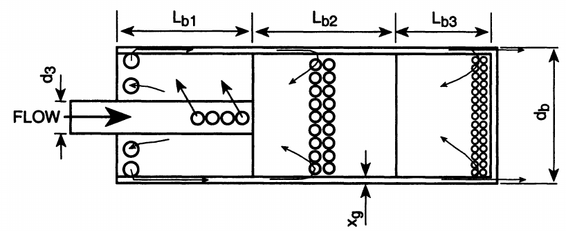
Here is a schematic.... but it has not copied all the lines on the drawing... so this is not exactly correct! (to protect the innocent?). Don't bother copying this schematic, as it will be as loud as an open pipe.
View attachment 134226
Trouble is, it was "Company Business" (I.E. not my "intellectual property", as the employee!) - so when I left, all my papers had to remain on site (pre-computer anyway!). SO it is an "Hypothetical memory" of what may - or may not - be true. (Protects the innocent, because it is not exactly accurate!).
K2
Hello Steamchick
There is no secret in this silencer.
I first read about the annular gap silencer in Blair's book (R-186). And I found a lot of information on this silencer.
In [3] Blair shows that the minimum annular gap is 3.2 mm. But if you consider that a two-stroke engine throws out unburned oil and carbon deposits form inside the silencer, then Blair recommends an annular gap of 3.5 mm.
"This annular dimension is on the borderline for potential carbon build-up and resultant clogging, so a value of XAN of 3.5 mm is probably a more pragmatic"
Blair recommends a 15% larger annulus area than the muffler inlet pipe area.

The most advanced silencer design is presented by Blair in [4].
39342593xj.png

The first expansion chamber, further the exhaust gas exits through a narrow annular gap. 2 and 3 chambers are wide-band Helmholtz resonators. As Blair writes in [4]):
"There are several other factors that contribute toward the overall effectiveness of this
silencer:
(i) The effilux of hot exhaust gas occurs through an annular ring into air that is at a much
lower temperature and higher density. There is a large contact area between the two
surfaces. This produces considerable damping ofthe turbulence in the exiting exhaust
gas plume, thereby reducing the high-frequency noise inherent in that source. This
approach to silencing turbulence noise is conventional practice for aircraft gas tur-
bines.

(ii) The central body houses side-resonant cavities that can be used to tune out particular
frequencies with a high noise content. The flow passing the entrances to these cavi-
ties is moving at right angles to those apertures, and at particle velocities that are
closer to acoustic levels than those in the conventional silencers shown in Figs. 7.7
to 7.9. Thus, the assumptions inherent in acoustic theory for Helmholz resonators
[7.36] are approached more closely, and the application of that theory can be applied
with a little more confidence in the quality of the outcome.

(iii) The exhaust pressure pulsations entering the first chamber, a diffusing silencer sec-
tion, have the normal and considerable amplitude associated with such waves. The
first box reduces the magnitude of the pressure oscillation before it enters the annu-
lus en route to the atmosphere, passing the several resonant cavities as it goes. How-
ever, the outside skin of the silencer does not experience the pressure forces due to
the full magnitude of the primary oscillation in the first box, as is the case with the
other silencers shown in Figs. 7.7 to 7.9, and so the outside skin vibrates less than it
does in those other silencers. Later on, Sec. 7.7 presents a discussion whereby double-
skinning of the outside of a conventional silencer may be necessary to prevent that
vibration from being a significant source off noise. That necessity may be eliminated
by using a laminar flow silencer."

The most difficult thing is to calculate the size and number of holes for 2 and 3 Helmholtz chambers. Blair gives a link to the numerical modal calculation method [5]. Other numerical acoustic calculation methods are not accurate for this type of Helmholtz resonator. Because these are Helmholtz resonators with distributed parameters, you need to know the wave function, differential equations, etc. Therefore, either do the calculation using modal analysis[5] or use programs for calculating by the finite element method FEM (or the finite volume method FVM). Nobody knows the frequency response of the motor. Therefore, I believe that first make a silencer, but do not drill holes in chambers 2 and 3. Start the engine with this silencer, measure the frequency response of the engine. Find the noisiest frequencies you want to dampen. Next, calculate the number and size of holes for 2 and 3 chambers of the Helmholtz resonator. Then assemble the silencer and again measure the frequency response of the muffler.

Why are these silencer not mass-produced? Because this silencer is not technologically advanced for quick production. In the modern world, all mass producers strive to make quickly, sell quickly, quickly and get a lot of money for a quickly made product. And in my personal opinion (and the opinion of philosophers), the decline of technology in modern civilization began in 2005-2008.

I have all the literature listed below in electronic form.
[1] Geoffrey Roe: The Annular Discharge Silencer
[2]Journal of Sound and Vibration(1974) 33(1), pp. 29-39
THE SILENCING OF A HIGH PERFORMANCE MOTORCYCLE
G. E. Roe. (Receired 20 June 1973, and in revised form 25 September 1973)
[3] The basic design of two-stroke engines Gordon P. Blair. 1990 ISBN 1-56091-008-9
SAE Order No. R-104
Chapter 8 - Reduction of Noise Emission from Two-Stroke Engines
8.5.3.2 A possible absorption silencer segment for a two-stroke engine
pp. 382-385
[4] Design and Simulation of Four-Stroke Engines Gordon P. Blair 1999 ISBN 0-7680-0440-3 SAE Order No. R-186.
Chapter 7 - Reduction of Noise Emission from Four-Stroke Engines. 7.5.4 The Laminar Flow Exhaust Silencer pp. 723-725
[5] Free Gas Pulsation of a Helmholtz Resonator Attached to a Thin Muffler Element
Peter C.-C. Lai Copeland Corporation, Werner Soedel Purdue University
International Congress and Exposition, Detroit, Michigan, February pp.23-26, 1998
 
Last edited:
Yes you should use degrees K...
Steamchick- just spotted this & can't resist- from post #39, one of my pet nitpicks- it should be Kelvins, not degrees Kelvin. The units for the other scales are degrees, but for reasons unknown, the Kelvin scale has the unit of Kelvins. Gotta love the Poms!!
Totally unrelated to the topic at hand- but hey, that's what nitpicks are for:):):):)
No "degrees" used due to it being an absolute scale. Apparently.
 
I engage in discussions to learn... By tweaking the lion's tail you learn how to "Growl...". Thanks for the feedback.
Especially the detailed stuff from Multics!
Curiously, I designed a silencer for a single blast of Compressed air: About 2 litres at 28bar being released to atmosphere to permit a high speed actuator to open a circuit breaker.
I only had a magazine article explaining Dr Roe's annular discharge silencer, so didn't include any Helmholtz resonators. But the silencer reduced the noise by 11 DbA compared to the previous expansion boxes that had been used.
Source (1m from sound meter) 135DbA reduced to 124DbA. (inside the factory).
At 100 m the sound power was down below the 95Db regulation limit. At 1 mile from the site you did not notice the sound... instead of it making birds fly up!
K2
 
There is a comment about manufacturing of the Annular discharge silencer...
"Why are these silencer not mass-produced? Because this silencer is not technologically advanced for quick production. In the modern world, all mass producers strive to make quickly, sell quickly, quickly and get a lot of money for a quickly made product. "
I agree with this, except the market liked these silencers on the Norton Commando like "Marmite". Some said "Great!" while others said "They look horrid! - spoil the looks and sound of the bike."
Produced to achieve the Regulation silencing that had been introduced, these silencers performed well and kept that "sound feel" away up through the rev and power range. (Apparently, from road tests I remember...?). But "many" missed the growl from the Commando of the earlier long reversed cone silencers - and many preferred the aesthetic looks of earlier silencers, so as with many things, designers can't just "sell what works best" but need to pander to "the whims of the paying public" - or more likely the artistic designers who "need" to keep changing styles with fashion - to keep on selling their products.
Selling "aftermarket" - less than legal - silencers is quite big business, as customers often want a "noisier" exhaust on a motorcycle than the Regulations permit a manufacturer to supply on a Type Approved product. - And exhaust gases are very corrosive, so silencers rot! Then "noisy" silencers are often much cheaper than original equipment Manufacturers' items.
Just my opinion though...
K2
 
It was clear that it was a silencer for a high-voltage switch. I studied to be an electrical engineer. High-voltage switches are oil-filled with transformer oil, gas switches with sulfur hexafluoride SF6 gas or air switches - extinguishing the electric arc with strong air pressure (very loud). A "fast" high-voltage switch would be promising - opening the contacts at the moment the sinusoid of the electric current passes through 0. Then there is no spark at all, these are transients in electrical networks. But with an AC frequency of 50 Hertz, an oscillation period of 0.2 seconds - this would require a very, very fast synchronized high-voltage switch.
There are mufflers for two-stroke engines in Gordon Blair's books. Book "The basic design of two-stroke engines" Gordon P. Blair. 1990 "R- 104." has the source code for the programs at the end. At the end of the book is an appendix with source codes for Microsoft BASIC programs. On the official website of the SAE you can download free of charge an introductory excerpt of this book (in high quality print resolution) with the source codes of the programs. ProgList 8.1, DIFFUSING SILENCER and ProgList 8.2, SIDE-RESONANT SILENCER. The geometric dimensions of silencers are given in Blair's books "The basic design of two-stroke engines" and "Design and Simulation of Four-Stroke Engines" Gordon P. Blair. The programs are small, around 180-240 lines of source code. I fixed 2-3 syntax errors in the programs and compiled the programs in modern QB64-basic to work in the OS Linux. Well, I don't like OS MS Windows. The programs work quickly, a 240x320 terminal window opens, we enter the data and the program draws a graph of the attenuation of the muffler.
In the book "Design Techniques for Engine Manifolds: Wave Action Methods for IC Engines". D. E. Winterbone, R. J. Pearson, 1999 Proffesional Enginering Publishen - i bought this book and it was recently brought to me from Germany to Kazgulak.
And also the site of Dr. Martin Hepperle. Program for calculating the resonator and muffler for a two-stroke engine: JavaPipe: Tuned Pipe Designer MainFrame. Dr. Martin Hepperle wrote this program using book Bönsch, H. W.: "Der schnellaufende Zweitaktmotor", Motorbuch Verlag, Stuttgart, 1982.
 
Hi Multics. You seem to know a hell of a lot more than I do! Yes, it was a 400kV SF6 circuit breaker. At 50Hz there are 100 "zero voltages" per second. The CB had to clear the fault-current at the first or second "zero" - And it did. Within 1 1/2cycles (0.03secs.) to fully open. The sensors and pre-switches and valve servos all did their stuff in <0.1secs. 105G initial acceleration recorded on the piston-shaft of the actuator before the friction broke at the contact and the contact started to slide before opening a gap. This was because the whole structure and drive rods acted as a "spring" that had to be loaded to develop the force to overcome static friction at the electrical terminals. Then the stored energy in that spring accelerated the contacts faster as the "brakes" were applied in the actuator, to remove the kinetic energy of the system, residual potential energy of the "spring" of the system (now reversed in direction), and get everything to rest at a kinetic and potential energy zero, to eliminate overtravel and "clatter" when everything reached the full open positions.
The software (to do the dynamic model calculations - 3 per night taking 15 minutes per run!) was written by a guy who was a Doctor of Maths using Fortran, for the Company mainframe computer.... Anyone remember that? It was 40 years ago... (Simple PCs became available the following year...). I lived with reams of print-out for a year with that one. I guess the whole dynamic model could be created on your Smart phone now, if you knew the maths... Or would today's kids simply take a selfie next to the job and send it to someone saying "It's broken. What do I do now?"
At least the top Engineer in the UK transmission division of the Electricity Board approved my design - and a variant was used for the 145kV ring-main around London. Should be about obsolete now with it's planned 40 year service lifetime? - Like me, I suppose...?
K2
 
Back
Top