Edgar T Westbury's 15cc Petrol 4 cylinder engine - it could be a long post!

Home Model Engine Machinist Forum

Help Support Home Model Engine Machinist Forum:

This site may earn a commission from merchant affiliate links, including eBay, Amazon, and others.
Mike,

I think I have already mentioned it to you, around 60" would be ideal for a single Seal, for two Seals, you would need to add about another 6" to 9" inches at least.

When I was going to build it, I was looking at the Riva Aquarama with a Seal in it, with the engine mounted in a scale position, in the rear 1/3rd. You have to build that large to be able to accommodate the vertical layout of the engine, as because of the wet sump, it can't lay on it's side like you can do with a glo engine.


Bogs
 
Bogstandard said:
Mike,

I think I have already mentioned it to you, around 60" would be ideal for a single Seal, for two Seals, you would need to add about another 6" to 9" inches at least........
Bogs

Thanks Bogs, I must admit to being concerned with building the engine and not the boat but when I saw that 42" Huntsman running on the electric motor I was shocked! So I will look again nearer to time to see what to put it in. A scaled up/down RAF second world war rescue craft may be a thought........

HS93 said:
I had the same 42" Huntsman when I was very young with a 15 cc gannet in it(petrol) and it went well, when you get to prop positioning give me a shout as you have to be very carfull with this boat, is yours wood of fiberglass and is it a kit as I may be able to give you some advice.

peter

Hell Peter, the boat is off a plan and not part of a kit. Bearing in mind what Bogs, has said I may need to review the model to use.......luckily Steve my brother who was having a 'go' at building the boat has slowed to 'slow' speed so a change of model would not be a great problem, getting into the workshop to build the engines is!!!! However I would be grateful to take up your help offer when we get nearer to that phase of the project.

Thanks for the interest.

Mike
 
if you decide to build a RAF crash tender I can help, I have a lot of info on the full size boats and have built a few. one I am building at the moment, you can get a hull for a 46" version in fiberglass and I am shore two engines would fit, I have a mate with one and i can get him to measure the space available, they where a high speed boat as well twin screw,sorry to the non boat people.

peter

DSCF0005 (900 x 675).jpg


DSCF0012 (800 x 600).jpg


e70e.jpg


Boatlarge1 (800 x 560).jpg
 
HS93 said:
if you decide to build a RAF crash tender I can help, I have a lot of info on the full size boats and have built a few. one I am building at the moment, you can get a hull for a 46" version in fiberglass and I am shore two engines would fit, I have a mate with one and i can get him to measure the space available, they where a high speed boat as well twin screw,sorry to the non boat people.

peter

Hello Peter, re the measurements, that would be a big help in deciding. So if you can get the measurements that would be most useful.

Mike
 
Pleased to get out into the workshop and carry on with the Seal build. Today I spent my time boring out the previously made valve guide blanks. Once this was completed I reamed all the guides 3/32" to match the valves and decided to press all the guides and cylinder liners into place. Before pressing them home using the Myford face plate and tailstock, I checked the depth of recess and the amount of clearance on the cylinder liner or valve guide. Then I measured how proud they were so ensuring they were pressed fully home.

The next task will be to face the block off to size (allowing 5 thou for the base to be cleaned up) so I spent my last time setting the block on mill ready for tomorrow. I did a test running the new power feed and am wondering whether the control of speed has a wide enough range...... Will see the next time....

A few pictures the help.....
[/img]


100_4657.JPG


100_4661.JPG


100_4658.JPG


100_4663.JPG
 
Wot they said... good to see you back, Mike!

Cheers, Joe
 
Today I managed to get the surface fly cut back and also the base but have left 3 thou for final lapping of the top and bottom. Hope its enough! The home made power feed worked great and certainly helped me with the physical side of turning x axis. So that was some good news!

Fitted the valves and couldn't resist trying a couple of springs just to see...don't know why we do it...get ahead of ourselves...anyway I will now sort out a cutter to cut the valve seats.

Decided to test out my idea for cutting the HT steel in half bought for the two crankshafts. My method is to tap the end of the bar (within the allowance of the finished length of the cranks) and secure two pieces of flat bar to it. These are then clamped to the saw table. This will allow both to be secured and remain there once the cut has been made.

Decided to try and make the two from one bar of HT (its very expensive in the UK) bit have left it for the next session when I will be fitter (don't want pieces flying around he workshop!

If it works all right I will start to make the crankshafts next.


100_4674.JPG


100_4676.JPG


100_4784.JPG
 

Nice work Mike!

Good to see you back at it.
 
Sorry again for such a long delay but I have been able to some limited progress shown below. I did start on the con rods but to be honest felt I over elaborated the work. I made a fixture to machine the top of the con rods using a small 3" rotary table and tried to use it as I did when making the chess set. However, whilst the top radius worked very well working out the angles seemed to take more time than if I just profiled the blanks! Because I was using some aluminium from the scrap box I reviewed the whole process and have ordered some bar to a known specification.

I have therefore started to make the pair of crankshafts and adopted a simpler system (or I hope I have!). I ordered two blanks from Hemingways (they supply a kit of parts and also materials) and decided just in case to normalise the bars.

The it was over to the milling machine to remove the waste and then on to the lathe where I have turned the first end to overall size before continuing with the others, but at least its a start! For a more detailed write up have a look at my website www.mikes-models.com

100_4817.JPG


crank to profile small size.JPG


100_4887 - Copy.JPG


100_4784.JPG
 
Hi Mickey,

Good to hear from you.

Best Regards
Bob
 
Thanks Bob,

It seems Australia and New Zealand are having a rough time lately. I hope you and your family are ok.
 
Mickey,

We are fine and we have been very lucky this year, apart from some very localised flash flooding during January, some 50km NE of us. I don't want to push our luck as Adelaide is an earthquake prone area.

Best Regards
Bob
 
Hi Mickey,

This project is very cool!

When do you will have new news for us?

Cheers,

Alexandre
 
Hi, due to Health, the odd wooden toy for my first grandchild, and sorting out a wooden shed (workshop now I have insulated it) for all things wood (and I hate wood! - Well I must admit I like turning wood though) then getting tendinitis on my left hand its been very very frustrating re metalwork!

However the end may be in sight.....I am hoping another week should see me back into the workshop and finishing off the two crankshafts and I can't wait! You take your health for granted when you are fit, my advice is don't.......its a gift.....

Thanks for the interest though. I will be adding details when I can get some work done.....

Mike
 
Okay Mike... I understand!

I hope your health better soon and I will be here to see your progress!

Best regards,

Alexandre
 
I agree Jason, thanks and thanks to everyone else for their comments. I have a couple of options though, I can try for replacement castings or have fun sorting them out. The only replacement I would go for though is a sump but I will leave that until I see how my fix turns out. Plenty of time for that though........On with the build says I!

Well today was a good day. The first of many I hope. I wanted to complete at least one blank camshaft in steel. I expect I could have made 1 ½ blanks if I hadn't made a mistake with the taper end of the camshaft.

I had completed all the fussy bits and then took too much off the 1/8th” tail. So that was parted off and will be kept as a comparator piece (scrap really!). I was a little miffed that I managed to get all the parts within 0.001” only to make a silly mistake at the end (literally).

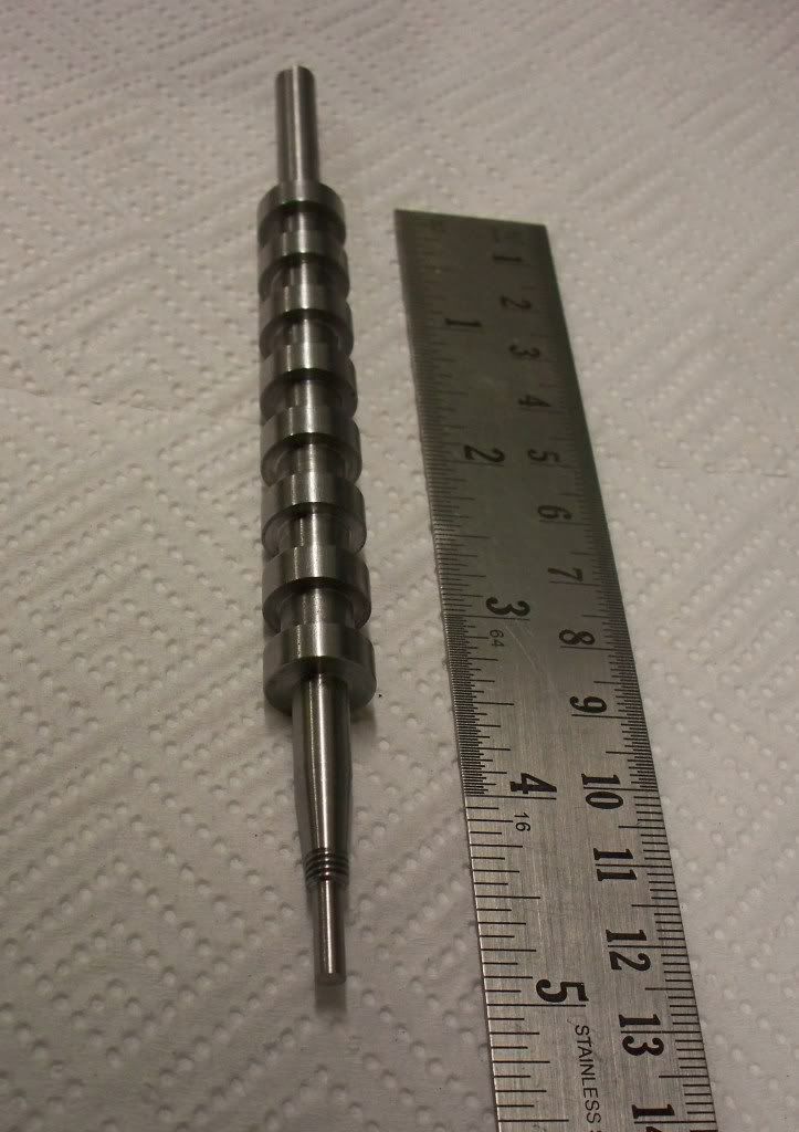
At least the structure I put so much time into for machining seemed to work. Indeed the time I took to make the nearly completed camshaft blank [see photo] was much reduced for the second attempt. This particular camshaft is made from BMS (bright metal steel) and will be for my hardening experiment. I have another two blanks to make over the next couple of days but these will be turned from stainless steel. Not sure if it's the best material but it is surely harder wearing than BMS.

sealcamshaft28032009012.jpg


The only task remaining to complete today's example is to drill the small hole in the opposite end from the taper. This is to allow a small steel pointer to be used when turning the camshaft in the fixture designed by Steve Huck (thanks again Steve!). I will drill the hole when I have all three blanks machined to the same point to make use of the set up time involved.

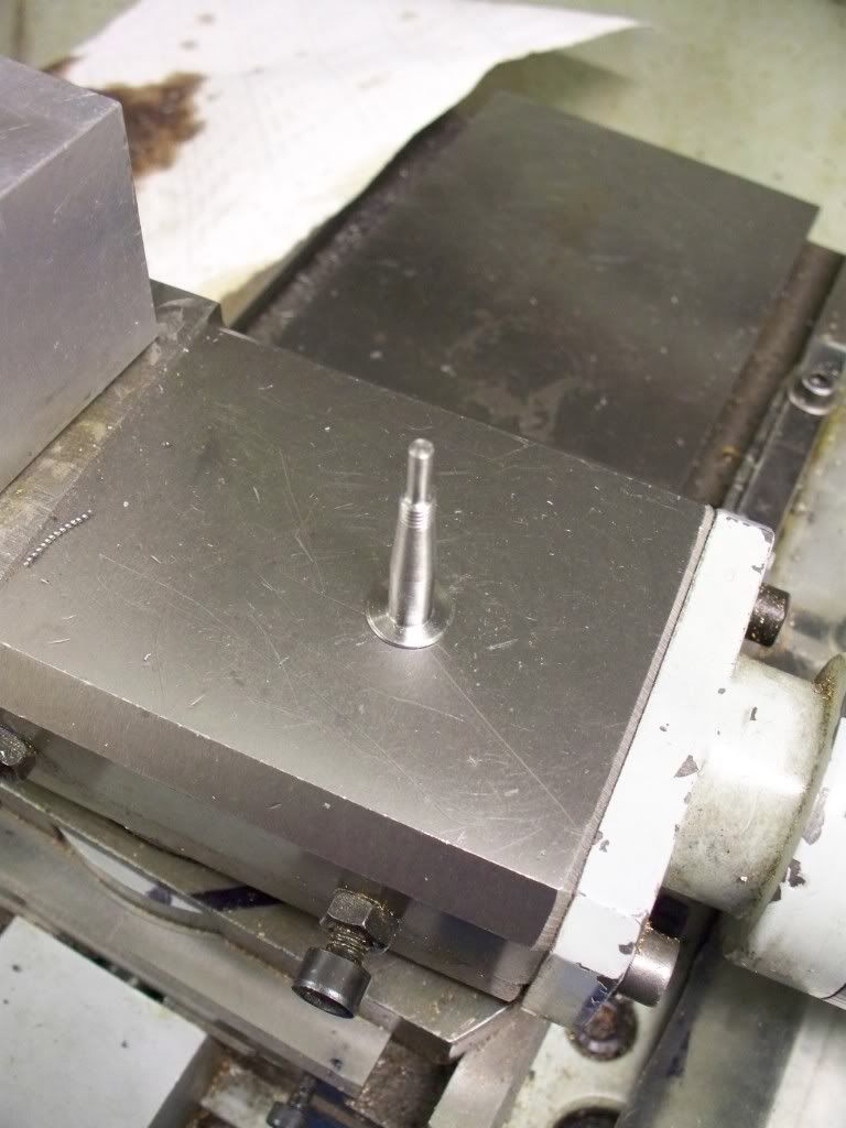
I decided that the best way to approach the task of producing the cam blank was to machine the awkward part first. The first job was to centre the bar in the 4 jaw chuck with the minimum showing. Then the bar was turned down first to 0.250” diameter. Using the digital readouts the start and end of the taper was lightly scored on to the bar, along with the measurement of the length for the thread.

It was then another turning job to bring the diameter down to suit the 2BA thread which was then threaded by use of the die held in the tailstock holder. Once this was carried out the thread was then reduced to size. The next procedure was to turn the 10° taper just in time noticing that the tap setting should be only 5°. I must admit to a little apprehension when sizing the job up especially blending the taper to the threads. In the end though there wasn't any difficulty and the thought was far worse than the deed (as I have found with many engineering tasks done for the first time).

Once the tapered end was completed the 4 jaws were released and the bar drawn out, centered again, and then parted off with sufficient length to make a complete camshaft blank.

The bar was reversed in the 4 jaw with only enough bar showing to allow the dti to be used to centre the bar. After facing off the end was centre drilled so a live centre could be used in the production of the camshaft. This was the first time that I thought about how I was going to turn the cams in the next stage. In particular because the taper end was very small and certainly too small to centre drill and use against the live centre, but likewise I couldn't grip the nice taper end in the 4 jaw chuck. So I decided to produce a brass bush that would protect the shaft with the taper [photo] leaving the larger diameter faced end to be held with the live centre.
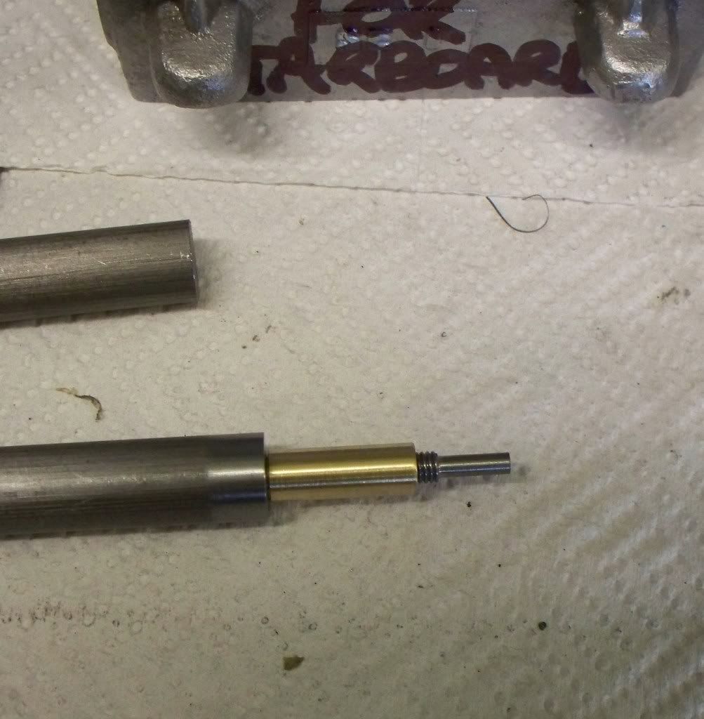
sealcamshaft28032009029.jpg


Once the bush was drilled and reamed, it was parted off and the bush and shaft placed in the 4 Jaw chuck, using the dti again to get it running true. I decided (with fingers crossed) that I better check the shaft was true across its length and I was really pleased to find no discernable difference between ends. Now the test would be if my new chart with the dimensions on (chart is too posh a term for the scrap of paper) would work.

Starting with the end nearest the chuck, the digital readouts proved there worth as I set the position of the saddle into the correct position. With a new insert in the parting off tool I took the cut to depth. Set the y axis reading to zero and moved the saddle to the end position and cutting to 0.005” of the finished size. This left a middle piece to be removed, again to within the 0.005” of finished size. I now carefully moved the saddle between the two cam edges using the parting tool to turn down the last 5 thou to finish across the gap.
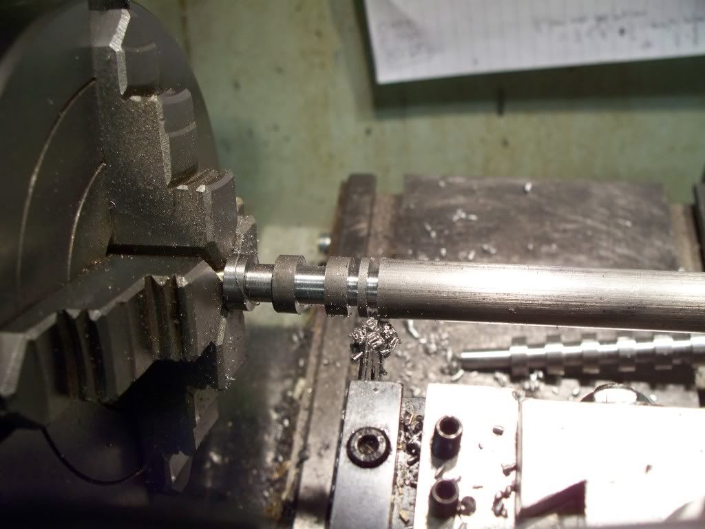
sealcamshaft28032009005.jpg


Then the saddle was moved towards the tailstock and into position for the next cut to within 0.005” before cutting the end position, removing the centre part last. This was repeated until all 8 cam blanks were cut. The tool was changed and the end nearest the tailstock then turned to finished size using the half method. Since learning about the half method I can nearly always get to the 1 thousandths of an inch allowance I give myself. Well unless I go stupid as I did earlier on in the day, but that wasn't a failure of the methodology, rather the stupidity of the operator!!

sealcamshaft28032009040.jpg


And that was enough for me today. At least I made progress. Hopefully tomorrow I will be able to produce another blank (I would like to get both done really but that depends more on health issues than time ……)
Hello, I have a question. What is the half method?
 

Latest posts

Back
Top