
You are using an out of date browser. It may not display this or other websites correctly.
You should upgrade or use an alternative browser.
You should upgrade or use an alternative browser.
Edgar T Westbury's 15cc Petrol 4 cylinder engine - it could be a long post!
- Thread starter Metal Mickey
- Start date


Help Support Home Model Engine Machinist Forum:
This site may earn a commission from merchant affiliate
links, including eBay, Amazon, and others.
Shopguy,
Really nice job on the camshaft! I bought the Whittle Aero V8 from Hemingway about a month ago (next project). I've been going to school on this thread. I don't no why I picked that engine for my first multi cyl. I guess I didn't realize exactly how small it was. The camshaft rough stock is about 5/16 OD x 3L. Keep the cam info coming I need more school
Tony
- Joined
- Feb 17, 2008
- Messages
- 2,326
- Reaction score
- 440
MM
The cam shaft looks great. :bow: :bow:
Tony(Cobra428)
Be aware that the Whitlle cam shaft drawings were WRONG.
I don't know if the published drawings were ever corrected.
There is a Yahoo group for this engine and there is info on this both in threads and the files section.
http://groups.yahoo.com/group/WhittleV8/
Gail in NM,USA
Thanks Gail,
I found that site and look it over occasionally. I have a little time yet to start that project. I also found a site where a guy drew all the parts in CAD to check out the mistakes (don't know if he'll share yet). I didn't look into this project to deep before I jumped in. Worst case I've been doing CAD for 25 years so I can make 3d model too. I do that in work I'd hate to go home and do it somemore!! :'(
Tony
Metal Mickey said:Hopefully tomorrow will see an end to cam turning for a little while although I still have one more to make. At least I now have a pair of camshafts that should allow me to tackle the main castings, namely the cylinder blocks.
If you can stand it, You might think about making the third cam while you are still in the groove. Everything is setup and the process is in your head. Your chances for a quick, smooth, mistake free piece are about as high as it can get right now.
Metal Mickey
Well-Known Member
- Joined
- Jul 5, 2008
- Messages
- 612
- Reaction score
- 6
stevehuckss396 said:If you can stand it, You might think about making the third cam while you are still in the groove. Everything is setup and the process is in your head. Your chances for a quick, smooth, mistake free piece are about as high as it can get right now.
I am going to make the third over this Easter with a bit of luck and your right Steve, 'in the groove' is a good point. The cylinder casting work today is a small diversion (but a nice one) before going back into the fray as it were........
Thanks for your support Chuck, Earnie, Tony, Bob,Gail and special mention to Steve again. He has been a lot of help, like so many others on this site.
From all the praise the photo's must hide the faults! Good camera.....good camera....... :big:
Metal Mickey
Well-Known Member
- Joined
- Jul 5, 2008
- Messages
- 612
- Reaction score
- 6
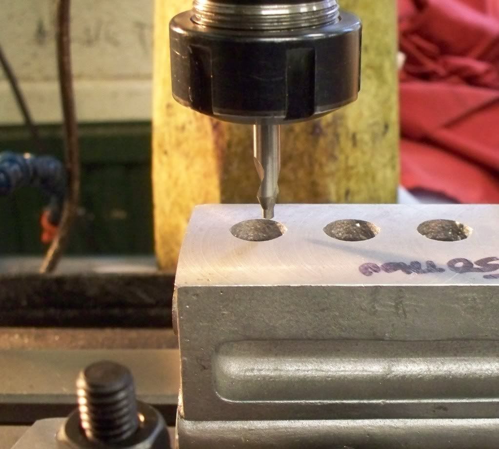
Today I spent quite a bit of time on working out the coordinates for drilling then reaming the holes in the cylinder block for the 8 valves and 4 cylinder liners. It's critical that measurement should take place from a machined surface and I choose the right hand side face when looking at the photo of the cylinder block on the milling table. I had previously set the casting parallel to the X axis by using the two plugs centre drilled previously.
I normally use my electronic edge finder that lights to show contact, and therefore the edge (after allowance for ½ the diameter of the end) of the part being measured. However the overhang on the edge finder would not allow measurement and I do no possess any slip gauges or the like so I made use of the 'wiggler' set I used before buying the electronic edge finder. It was quite nice to revisit an old friend as it were and the edge was fed into the digital readout, after allowance for the ½ diameter.
Because the cylinder block is a substantial casting and the critical nature of making sure the valves, cylinders, camshaft etc. line up, I made several movements to see that the end coordinates looked correct. It was during this exercise that I found the coordinates wouldn't work in relation to the 4 holes already there for the pistons.
When checking the dimensions against the other recently bought set of castings, I found yet again that my casting was significantly larger. So I decided to center the mill over the nearest cylinder hole to the datum face and confirmed the extra distance.
So after recording the measured difference in case it is needed later, I reset the DRO to zero and carried out the checks for the coordinates again. This time everything worked out fine and I decided to center drill the 8 valve stem holes. Then it was the turn of a 15/64 drill before reaming with a ¼ reamer.
The remainder of the session was spent adjusting the belts of the milling machine to reduce speed for boring and a start made on the first cylinder bore. However at the beginning of the next session I will make a plug of the correct size to use as a set standard for all four bores. Whilst each cylinder liner can be 'adjusted' to suit I would like to get them as near as possible to the correct size so I can produce the 8 cylinder liners as a batch. After all I should seek to increase my engineering skills, and accuracy is a measure of progress is it not.
Ignore the surface finish, there is several thou to come off yet, honest!
Overall a good session with the many checks proving of worth, even if there was not a great deal of swarf made!
p.s. can anybody tell me how to put small pictures in that can be clicked on?
Cheshire Steve
Well-Known Member
- Joined
- Mar 28, 2009
- Messages
- 69
- Reaction score
- 1
Hi Guys,
Well I now have a Seal too, on the production line. Mine came with most of the block machining done, and the crank done, but in many respects still a kit of castings, and no camshaft, pistons, valves, valve cover, but I seem to have the major castings. The machining looks good as far as it goes. It came with a single Westbury drawing of the main items (no electrics/carb on this drawing), plus I have acquired some of the appropriate ME magazines with the 'words and music' (i.e. how to machine it).
Clearly your camshaft machining details here are of great value - I will sure need them !
So maybe I can help in terms of the odd sizes of your castings. For example I can take dimensions of my castings, the Westbury drawings, and the drawings in the 1947 ME magazines - which are also dimensioned. Let me know if there is any way I can help - as what you have put on this forum has certainly helped me understand how to go about sorting the camshaft. I really appreciate it. I will be following in your footsteps - but probably quite a distance behind !
Steve
Metal Mickey
Well-Known Member
- Joined
- Jul 5, 2008
- Messages
- 612
- Reaction score
- 6
Cheshire Steve said:Hi Guys,
Well I now have a Seal too, on the production line. Mine came with most of the block machining done, and the crank done, but in many respects still a kit of castings, and no camshaft, pistons, valves, valve cover, but I seem to have the major castings. The machining looks good as far as it goes. It came with a single Westbury drawing of the main items (no electrics/carb on this drawing), plus I have acquired some of the appropriate ME magazines with the 'words and music' (i.e. how to machine it).
Clearly your camshaft machining details here are of great value - I will sure need them !
So maybe I can help in terms of the odd sizes of your castings. For example I can take dimensions of my castings, the Westbury drawings, and the drawings in the 1947 ME magazines - which are also dimensioned. Let me know if there is any way I can help - as what you have put on this forum has certainly helped me understand how to go about sorting the camshaft. I really appreciate it. I will be following in your footsteps - but probably quite a distance behind !
Steve
Hello Steve, please feel free to email me through this forum if you like or via my website www.mikes-models.com and we can chew the fat as it were. There are several problems with the plans and one major one relates to the camshaft with firung order and diagrams wrong! Thats not including the famous 2 9/8" dimension!
I may be able to help you out with the remaining bits to your article as I have a complete master set. Also I will check if I have a spare second sheet plan, but I am a little less confident on that one. I could always photocopy mine but it will be in several A4 sheets........
If you do decide to make the camshaft I can let you have a copy of the cutting chart and information given to me by Steve Huck. He has an article on camshafts in Model Engineering and MEB and is a very active and helpful member of this forum.
Any here to help if I can. I would be interested in your dimensions for the main cylinder block casting, cylinder head and sump. It would be interesting to see if there are three patterns out there!
Metal Mickey
Well-Known Member
- Joined
- Jul 5, 2008
- Messages
- 612
- Reaction score
- 6
I had a great Easter holiday with both my daughter Vicky and son Adam, with their respective partners Justin and Jemma, down for Adam and Jemma s engagement party. Whilst it is very nice to see them it does take me three or four days to recover after they have left, so workshop time has been nil until today.
I started by trying to work out where I had gotten to with boring the second Seal cylinder block casting. Previous experience had led me to leave a note on the milling machine the last session, saying it was all set up for the next cut. However the reading on the digital readout did not match my setting when double checking everything. I do not know where I went wrong but the y axis setting was incorrect. Looking through my scribbled note book I saw the reading I was on for the Y axis, but no workings on how I got there.
Whilst it was only a few thousandths out, it meant twice the error before getting to a round bore again. I could either go with the mistake for all 4 cylinders or make the first cylinder larger than it should be, but in exactly the right place. Since the error was contained inside the recess needed for the cast iron lining, I decided to alter the Y axis reading to what it should be and accept that the liner would have to be slightly oversize on its outside diameter, to accommodate the error. At least it would be in the right orientation.
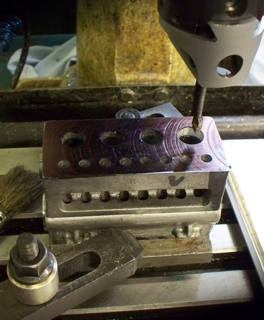
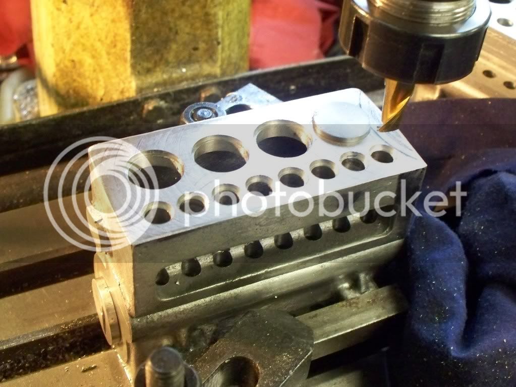
The rest of the morning was taken up with completing the 4 bores for the cylinder linings, including the top recess (see photo below) followed by drilling out the top of the eight valve bores, reaming to finished size. The penultimate task involved using a 3/8 diameter slot drill to make the recess required by the valve guides. Leaving me with the final task of the day, that of milling away the side of the casting alongside the valves. I wanted to get the casting squared at the same setting as the bores for both valves and pistons, although the final finish will be carried out when the casting is held on an angle plate at 90 degrees to its present position.
It will need to be faced properly on the angle plate, after having the inlet and exhaust ports machined, along with various stud holes. However by taking a cleaning cut now, I would have a good face to make sure the casting was set up as true as possible. That was enough for me for the first session back and it is progress at least.
I started by trying to work out where I had gotten to with boring the second Seal cylinder block casting. Previous experience had led me to leave a note on the milling machine the last session, saying it was all set up for the next cut. However the reading on the digital readout did not match my setting when double checking everything. I do not know where I went wrong but the y axis setting was incorrect. Looking through my scribbled note book I saw the reading I was on for the Y axis, but no workings on how I got there.
Whilst it was only a few thousandths out, it meant twice the error before getting to a round bore again. I could either go with the mistake for all 4 cylinders or make the first cylinder larger than it should be, but in exactly the right place. Since the error was contained inside the recess needed for the cast iron lining, I decided to alter the Y axis reading to what it should be and accept that the liner would have to be slightly oversize on its outside diameter, to accommodate the error. At least it would be in the right orientation.
The rest of the morning was taken up with completing the 4 bores for the cylinder linings, including the top recess (see photo below) followed by drilling out the top of the eight valve bores, reaming to finished size. The penultimate task involved using a 3/8 diameter slot drill to make the recess required by the valve guides. Leaving me with the final task of the day, that of milling away the side of the casting alongside the valves. I wanted to get the casting squared at the same setting as the bores for both valves and pistons, although the final finish will be carried out when the casting is held on an angle plate at 90 degrees to its present position.
It will need to be faced properly on the angle plate, after having the inlet and exhaust ports machined, along with various stud holes. However by taking a cleaning cut now, I would have a good face to make sure the casting was set up as true as possible. That was enough for me for the first session back and it is progress at least.
Metal Mickey
Well-Known Member
- Joined
- Jul 5, 2008
- Messages
- 612
- Reaction score
- 6
arnoldb said:This is really a magnificent example of engineering & machining ! :bow: :bow:
No no, I did this........
Metal Mickey
Well-Known Member
- Joined
- Jul 5, 2008
- Messages
- 612
- Reaction score
- 6
Todays session - the end of the beginning but not the beginning of the end!
Making the last camshaft proved the adage that practice make perfect. Not that I am in any way saying that the camshafts are perfect, far from it! But the last camshaft (I hope) took the least amount of time and for a change very few problems. Each time I nearly made a mistake I managed to stop myself from continuing, which is not an insignificant result believe me!
I needed to mark the cams to be cut with permenant marker towards the end.....just in case.......(thats experience!)
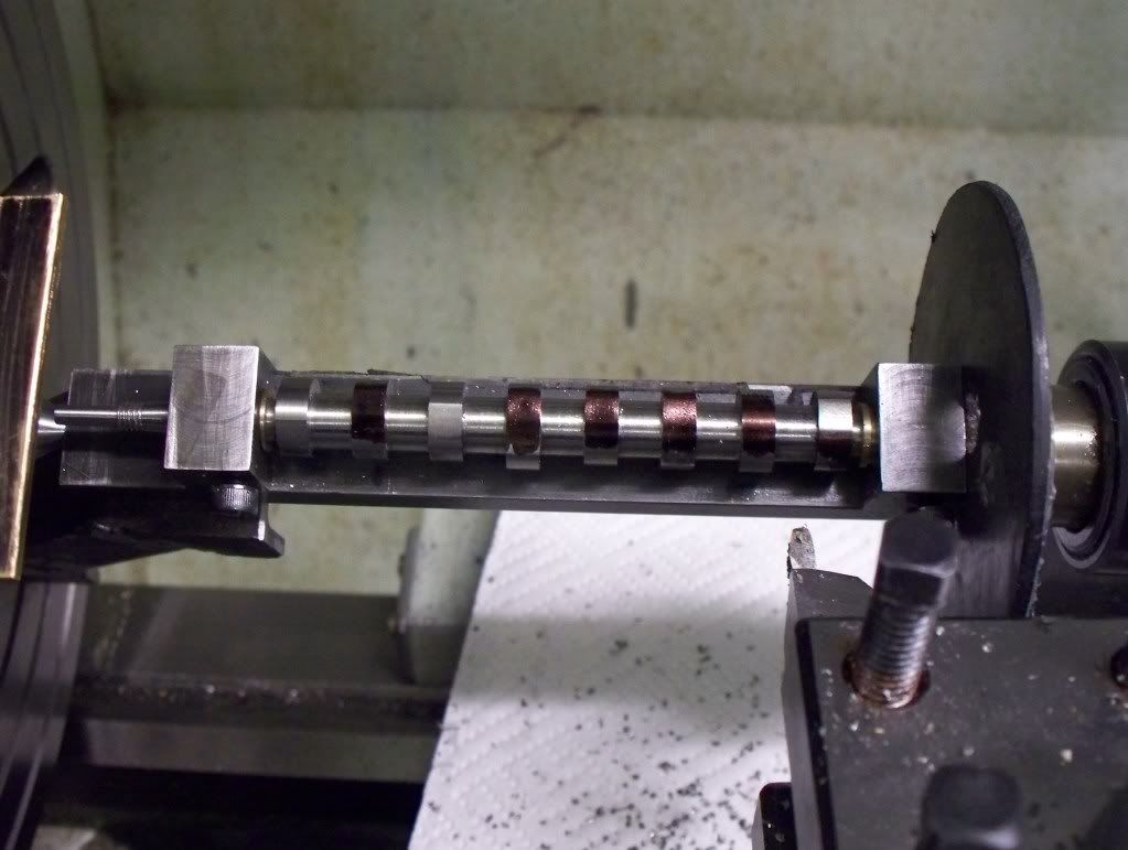
I now have a camshaft to harden as an experiment, and a completed camshaft for each Seal engine. Their production was not without incident and a little heartache at times, but I must go on record and thank Steve Huck for all his considerable help with cutting charts and giving me confidence when I had doubts, so thank you Steve.
The issue of errata on plans is something I have mentioned before. If you consider the fit for purpose test as in the UK then the Seal plans I have would not pass. If the plans were new then an error or two may be expected, however this design by Edgar T Westbury is over 60 years old. Is it too much to expect some obvious errors to be removed from the plans SOLD to the public? Let alone some major issues over the camshaft design. I know I lost some sleep over what was right and what was wrong. One thing I hope to come out of the Seal build is a comprehensive list of issues relating to the plans and they will be posted on my main website as well as my Blog for future builders. Additionally a copy of errata will be sent to the publishers of the plans, with a hope they amend their plans. We shall see.
The camshafts are not complete as yet, since as they have some finishing left but the machining is completed. A bi-product of completing this stage of the build is the much diminished fear factor of producing camshafts, since the 3 completed camshafts and the 50% practice camshaft (on a blank I corrupted early on) has given me some experience.
So its now onwards and upwards, with the next major items being the two crankshafts .ohhhhhh ..noooo........
Making the last camshaft proved the adage that practice make perfect. Not that I am in any way saying that the camshafts are perfect, far from it! But the last camshaft (I hope) took the least amount of time and for a change very few problems. Each time I nearly made a mistake I managed to stop myself from continuing, which is not an insignificant result believe me!
I needed to mark the cams to be cut with permenant marker towards the end.....just in case.......(thats experience!)
I now have a camshaft to harden as an experiment, and a completed camshaft for each Seal engine. Their production was not without incident and a little heartache at times, but I must go on record and thank Steve Huck for all his considerable help with cutting charts and giving me confidence when I had doubts, so thank you Steve.
The issue of errata on plans is something I have mentioned before. If you consider the fit for purpose test as in the UK then the Seal plans I have would not pass. If the plans were new then an error or two may be expected, however this design by Edgar T Westbury is over 60 years old. Is it too much to expect some obvious errors to be removed from the plans SOLD to the public? Let alone some major issues over the camshaft design. I know I lost some sleep over what was right and what was wrong. One thing I hope to come out of the Seal build is a comprehensive list of issues relating to the plans and they will be posted on my main website as well as my Blog for future builders. Additionally a copy of errata will be sent to the publishers of the plans, with a hope they amend their plans. We shall see.
The camshafts are not complete as yet, since as they have some finishing left but the machining is completed. A bi-product of completing this stage of the build is the much diminished fear factor of producing camshafts, since the 3 completed camshafts and the 50% practice camshaft (on a blank I corrupted early on) has given me some experience.
So its now onwards and upwards, with the next major items being the two crankshafts .ohhhhhh ..noooo........
Good for you mickey! You have completed , in my opinion, one of the hardest parts of building the engines. Get past the crankshafts and you are home free. . . . . except for all the other stuff.
Sounds like you are glad you finished the cams at this point.
Sounds like you are glad you finished the cams at this point.
Metal Mickey
Well-Known Member
- Joined
- Jul 5, 2008
- Messages
- 612
- Reaction score
- 6
stevehuckss396 said:Good for you mickey! You have completed , in my opinion, one of the hardest parts of building the engines. Get past the crankshafts and you are home free. . . . . except for all the other stuff.
Sounds like you are glad you finished the cams at this point.
Couldn't have done it without you Steve. I actually enjoyed making the last one strange as it may sound. yours is a good system Steve and I recommend it to anyone. Thanks. I may well tackle the crankshafts next, but via a saw
table to hold carbide tipped saw blades. Working on the drawings now. I know you use Alibre and must say I am a convert, even if its still a case of much to learn. Its the price I like!
Hello Bob, I am really glad to see you may be on the mend, I wish you well. Must have a look and see if you have got all your equipment in that building you have convinced the wife is your new home. Good one that Bob, good one!
Metal Mickey
Well-Known Member
- Joined
- Jul 5, 2008
- Messages
- 612
- Reaction score
- 6
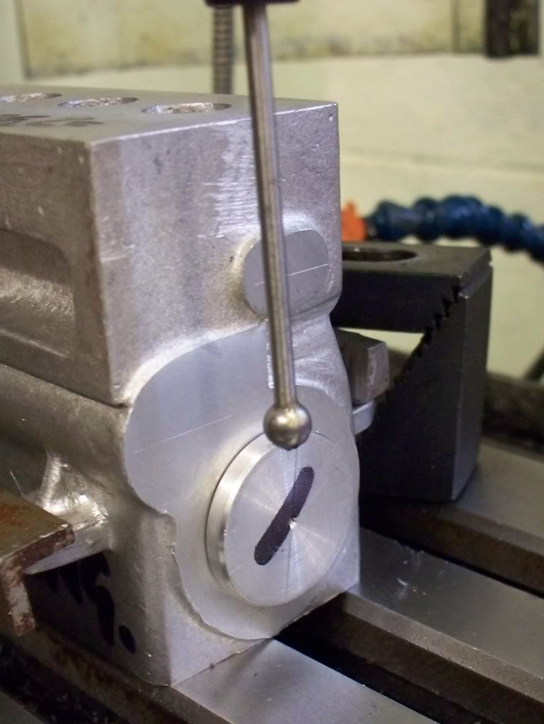
Well I'm back....At last I have been able to continue work on the pair of Seal engines. Today I managed to drill, then tap the oil filler holes on both cylinder blocks of the Seal engines. The set up time for any machining task is normally much longer that the metal removal and today's task was a fine example of the little extra effort in making another engine.
The first job was to set the adjustable angle vice up on the milling machine. The plans call for the oil dipstick filler hole to be at an angle of 20 deg to the engine blocks head. The way I set this angle was to use the digital angle meter I have. A much valued tool and a recommended addition to any workshop. It was first zeroed on the milling table then with the casting standing on a pair of parallels, the meter placed on its top and the vice adjusted until the correct reading was seen.
I decided that I would reduce the speed of the drill and use three different sized drills before starting the tap. This method ensured that the threads would be cut in line with the drilling. However I find it easier to move the casting to the bench and finish the thread, BUT only after it has been started in the same position as the drilling.
Here are a few pictures that will make the text clearer....
Similar threads
- Replies
- 115
- Views
- 34K