Edgar T Westbury's 15cc Petrol 4 cylinder engine - it could be a long post!

Home Model Engine Machinist Forum

Help Support Home Model Engine Machinist Forum:

This site may earn a commission from merchant affiliate links, including eBay, Amazon, and others.
Jasonb said:
Looks like they came from different paterns, on the sump the corner fillets are diagonal on the left and radiused on the right. Also the webs on the mounting lugs are different, one curved one straight.

Mike,

I agree with Jason. No way were they from the same pattern. That's a lot of faffing about for you. My commiserations.

Best Regards
Bob.
 
If you look even CLOSER ;D 8)

Sorry; QC humour!


Really though look at that photo again. Those two blocks are Mirror Imaged of each other.

:eek:


My Condolences on the Bad News,
Kermit


Set them in a launch as Port and Starboard motors with props that rotate opposite of each other??? Hey just trying to find one of them there silver lining thingies.
 
Mirror images ? Are you sure its not just that one is turned around ?

I have just registered, as I have just bought a part built Seal and spotted the forum while hunting for info. I was curious about the different castings. The original castings were by Craftsmanship Models in the late 40's and early 50s - my grandfather was one of the partners in the business. They made the Seal as designed by Westbury, and I think it was David Braid who made an upsized version, the Seal Major, of 30cc.

My grandfather died early in my life, and sadly all the records of those days seem to have vanished, but I have been thinking of collecting and or building the range of model kits made by Craftsmanship models (I started making models only about 18 months ago). Many of the kits are still in production by Hemingway, but if anyone has any original Craftmanship Models drawings I would be very interested. I was lucky enough to buy a Craftsman Twin complete with original 1948 drawings the other day.

Right now I am waiting for my new purchase to arrive. I might find I need to start from scratch ! Thats the trouble with buying a half built model unseen - you never know if it was a master craftsman who died half way through, or someone else who screwed it up so badly they decided to get rid. We shall see.

Steve
 
I agree Jason, thanks and thanks to everyone else for their comments. I have a couple of options though, I can try for replacement castings or have fun sorting them out. The only replacement I would go for though is a sump but I will leave that until I see how my fix turns out. Plenty of time for that though........On with the build says I!

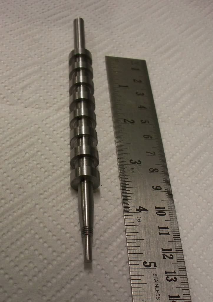
Well today was a good day. The first of many I hope. I wanted to complete at least one blank camshaft in steel. I expect I could have made 1 ½ blanks if I hadn't made a mistake with the taper end of the camshaft.

I had completed all the fussy bits and then took too much off the 1/8th” tail. So that was parted off and will be kept as a comparator piece (scrap really!). I was a little miffed that I managed to get all the parts within 0.001” only to make a silly mistake at the end (literally).

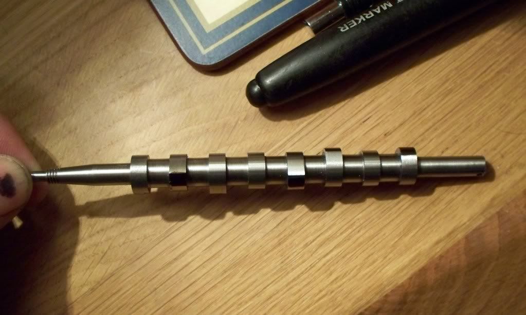
At least the structure I put so much time into for machining seemed to work. Indeed the time I took to make the nearly completed camshaft blank [see photo] was much reduced for the second attempt. This particular camshaft is made from BMS (bright metal steel) and will be for my hardening experiment. I have another two blanks to make over the next couple of days but these will be turned from stainless steel. Not sure if it's the best material but it is surely harder wearing than BMS.

sealcamshaft28032009012.jpg


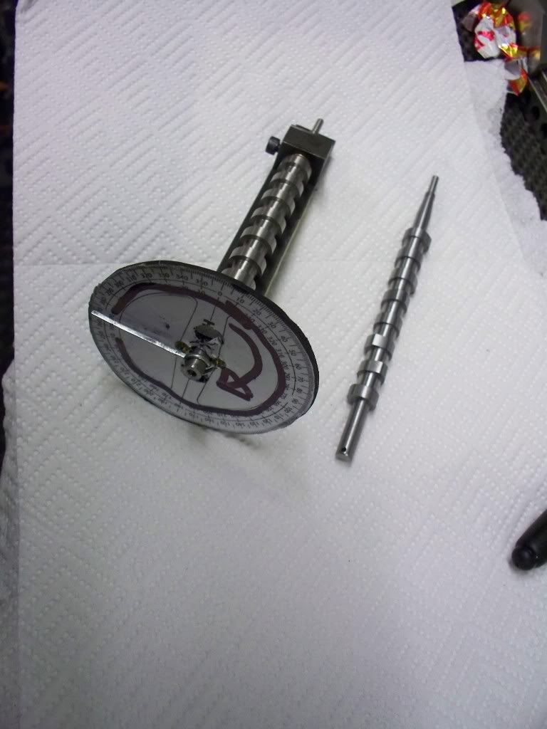
The only task remaining to complete today's example is to drill the small hole in the opposite end from the taper. This is to allow a small steel pointer to be used when turning the camshaft in the fixture designed by Steve Huck (thanks again Steve!). I will drill the hole when I have all three blanks machined to the same point to make use of the set up time involved.

I decided that the best way to approach the task of producing the cam blank was to machine the awkward part first. The first job was to centre the bar in the 4 jaw chuck with the minimum showing. Then the bar was turned down first to 0.250” diameter. Using the digital readouts the start and end of the taper was lightly scored on to the bar, along with the measurement of the length for the thread.

It was then another turning job to bring the diameter down to suit the 2BA thread which was then threaded by use of the die held in the tailstock holder. Once this was carried out the thread was then reduced to size. The next procedure was to turn the 10° taper just in time noticing that the tap setting should be only 5°. I must admit to a little apprehension when sizing the job up especially blending the taper to the threads. In the end though there wasn't any difficulty and the thought was far worse than the deed (as I have found with many engineering tasks done for the first time).

Once the tapered end was completed the 4 jaws were released and the bar drawn out, centered again, and then parted off with sufficient length to make a complete camshaft blank.

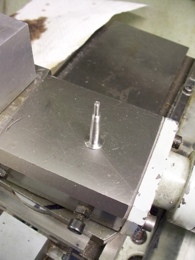
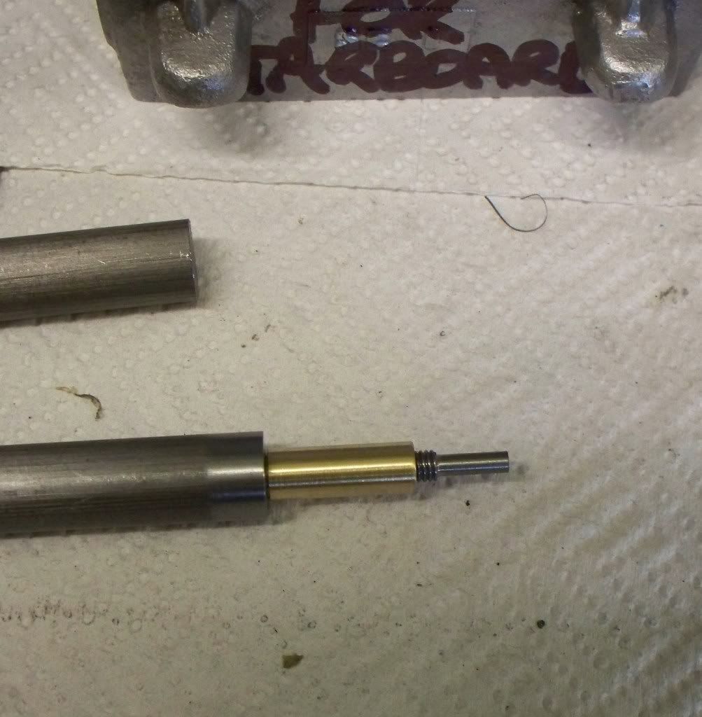
The bar was reversed in the 4 jaw with only enough bar showing to allow the dti to be used to centre the bar. After facing off the end was centre drilled so a live centre could be used in the production of the camshaft. This was the first time that I thought about how I was going to turn the cams in the next stage. In particular because the taper end was very small and certainly too small to centre drill and use against the live centre, but likewise I couldn't grip the nice taper end in the 4 jaw chuck. So I decided to produce a brass bush that would protect the shaft with the taper [photo] leaving the larger diameter faced end to be held with the live centre.

sealcamshaft28032009029.jpg


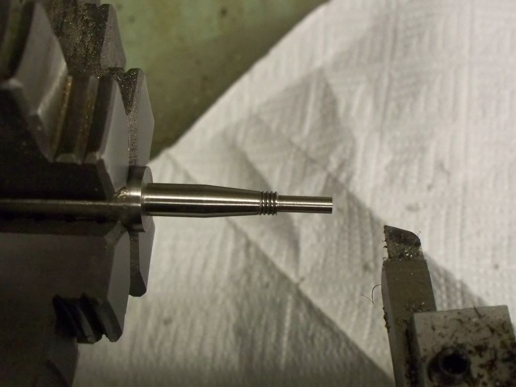
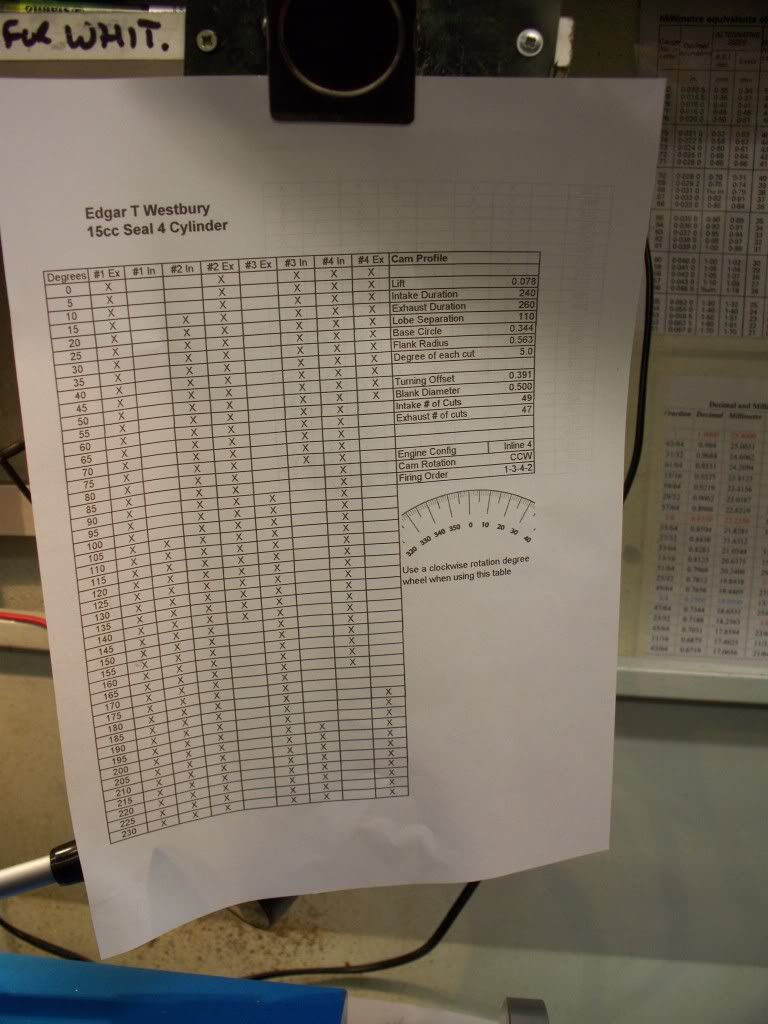
Once the bush was drilled and reamed, it was parted off and the bush and shaft placed in the 4 Jaw chuck, using the dti again to get it running true. I decided (with fingers crossed) that I better check the shaft was true across its length and I was really pleased to find no discernable difference between ends. Now the test would be if my new chart with the dimensions on (chart is too posh a term for the scrap of paper) would work.

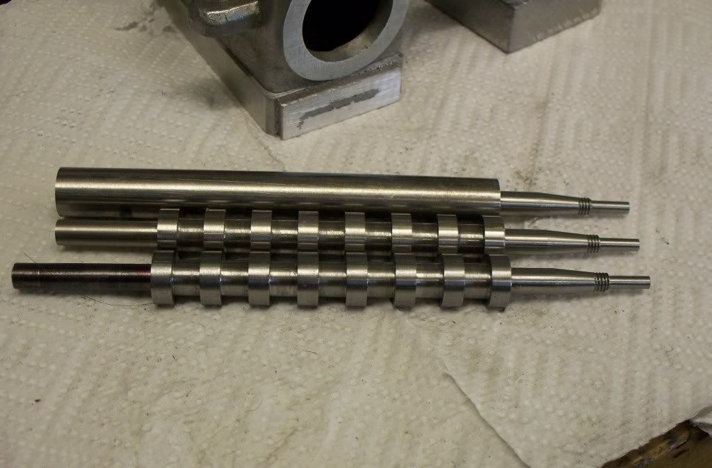
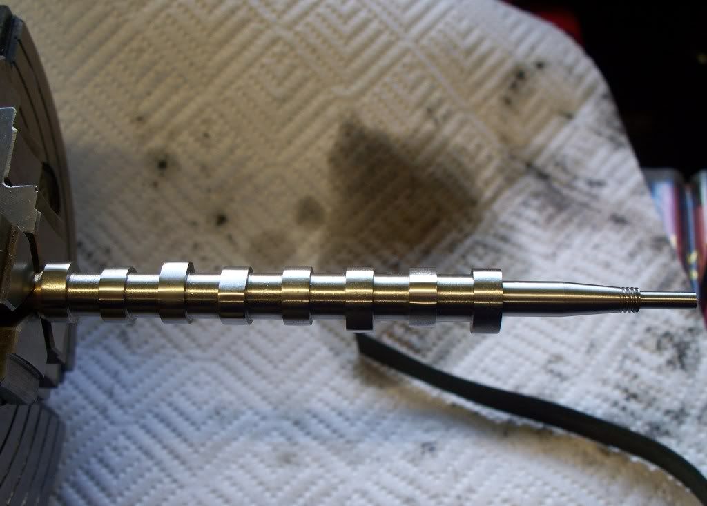
Starting with the end nearest the chuck, the digital readouts proved there worth as I set the position of the saddle into the correct position. With a new insert in the parting off tool I took the cut to depth. Set the y axis reading to zero and moved the saddle to the end position and cutting to 0.005” of the finished size. This left a middle piece to be removed, again to within the 0.005” of finished size. I now carefully moved the saddle between the two cam edges using the parting tool to turn down the last 5 thou to finish across the gap.

sealcamshaft28032009005.jpg


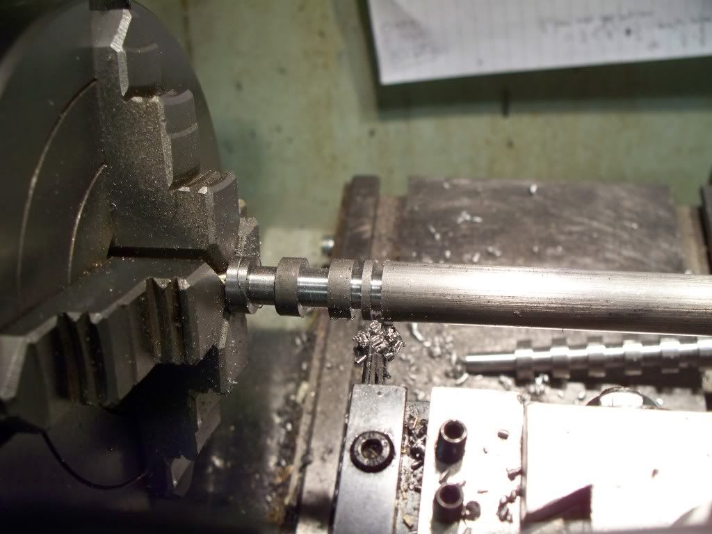
Then the saddle was moved towards the tailstock and into position for the next cut to within 0.005” before cutting the end position, removing the centre part last. This was repeated until all 8 cam blanks were cut. The tool was changed and the end nearest the tailstock then turned to finished size using the half method. Since learning about the half method I can nearly always get to the 1 thousandths of an inch allowance I give myself. Well unless I go stupid as I did earlier on in the day, but that wasn't a failure of the methodology, rather the stupidity of the operator!!

sealcamshaft28032009040.jpg


And that was enough for me today. At least I made progress. Hopefully tomorrow I will be able to produce another blank (I would like to get both done really but that depends more on health issues than time ……)
 
The tool was changed and the end nearest the tailstock then turned to finished size using the half method. Since learning about the half method I can nearly always get to the 1 thousandths of an inch allowance I give myself.


Uh sorry, but what is the "half method" ?

Great info by the way, I am learning quite bit :bow: :bow: :bow: :bow:


Ron
 
Hello Ron, I picked that tip up from this forum in answer to a post (can't remember who answered) but basically when you get to say 0.020 from the finished size you half whats left to cut, so your next cut is 10 thou. After that cut half whats left, say 5 thou, measure again then half whats left etc. It is easier to do than explain but it really works, I use it all the time and its improved my accuracy no end.
;D
 
The problem I see with that approach is that you are making a different depth-of-cut (DOC) each time. This means the stresses and consequent deflection are different for each cut. Also, your last cut may be very fine - ok with HSS but not so good with carbide.

I try to plan things out so my last two cuts are both the same DOC. That way, I can measure after the next-to-last cut, determine how much I'm really taking off with that DOC and, hopefully make only a minute adjustment to the last cut to arrive at the target size.

Using your example, I would, at 0.020 oversize, take a 0.005 DOC to reduce the oversize to 0.010, then take a 0.0025 cut to reduce the oversize to a nominal 0.005. If measurement showed the true oversize to be 0.005, then another 0.0025 cut would get me on size. If measurement showed 0.004, then 0.002 DOC for the final cut or 0.003 if the measurement showed 0.006.

If your technique works for you, by all means continue to use it. I'm only offering this method for folks who may want to try alternate ways of getting on size.


Thanks Metal Mickey, I have been doing something similar and didn't realize it.

Marv,
No wonder my carbide cutters are crap now! Learn something everytime I get on here.

keep it coming. :) :) :)
Ron
 
Well other than loosing an hour because of British Summer time, and watching Jensen Button win the Oz GP (well done to both Jensen and Lewis Hamilton for a great drive in a poor car - amazing from McLaren!)at 0600 hours, I managed to get out into the workshop for a second successive day! Brilliant.......

Onto the build though........ I managed to get both stainless steel camhaft taper and threaded ends done, and also cut out the blank cams completing one piece. So tomorrow I hope to complete the cutting of the cam blanks out of the second. Completing this phase before profile cutting the cams. The second photo below shows where I got to before stopping for the day .....ignore the left hand side of the shafts since they have yet to be cut to final size. Also there will be a cross drilled hole in the left hand side to accommodate Steve Huck's idea of a marker when I profile the cams.

When the camshafts are finished to size the left hand side is much reduced (and loosing the cross drilled hole).

29032009sealcamshafts006.jpg


29032009sealcamshafts017.jpg


I think that when I have managed to make the cams that will be a big psychological problem over. The next 'big' job will be the crankshafts but I may have a go at bringing the castings to size first before making the crankshafts. After that its all down hill! Only 16 valves, 8 cylinder liners, 8 conrods, 8 pistons................oh *&^%% hell what have I done!!!!! :big: Great though ain't it! Ho ho.

p.s. how do you post the smaller images that you click over to see a bigger picture? It looks nicer those that do it, so help please......
 
mklotz said:
The problem I see with that approach is that you are making a different depth-of-cut (DOC) each time. This means the stresses and consequent deflection are different for each cut. Also, your last cut may be very fine - ok with HSS but not so good with carbide.

I try to plan things out so my last two cuts are both the same DOC. That way, I can measure after the next-to-last cut, determine how much I'm really taking off with that DOC and, hopefully make only a minute adjustment to the last cut to arrive at the target size.

Using your example, I would, at 0.020 oversize, take a 0.005 DOC to reduce the oversize to 0.010, then take a 0.0025 cut to reduce the oversize to a nominal 0.005. If measurement showed the true oversize to be 0.005, then another 0.0025 cut would get me on size. If measurement showed 0.004, then 0.002 DOC for the final cut or 0.003 if the measurement showed 0.006.

If your technique works for you, by all means continue to use it. I'm only offering this method for folks who may want to try alternate ways of getting on size.

Thats interesting your comment with carbide because I cant get on with them I just bought another one recently but I get a better finish with HSS. Like you say if it works for you...and it does for me but nice to know there are other methods. I cannot claim ownership of this cutting methodology it came from the forum.

 
I'm no authority on cutter technology (hopefully someone who is will chime in) but my experience is that carbide doesn't like to take fine cuts (say <0.005") whereas HSS will happily shave off the proverbial frog hair if properly sharpened. It may be that, due to the metallurgy, carbide simply can't be sharpened to a razor edge - as I said, I don't know about the cause but the result is very apparent. Nevertheless, don't take my word. Do some experiments on your own and decide for yourself.

Carbide may be the weapon of choice in the industrial arena but I find it much less useful in the hobby modelmaking venue. HSS is cheaper, easier to form to the job and produces better finishes in the common modelmaking materials. Carbide is great for getting through mill scale and hard spots but is always my second choice for fine finish work.
 
Thanks mklotz,

I can live with that. Learn't something else today....great. :bow:
 
Not much work over the last two days so no photo's but I have turned up 6 bushes for the fixture. Looking at the ones that came out after the practice cam cutting I thought it best to pus a new pair of bushes to each camshaft. That way I will not be tempted to re use a damaged bush.

I have also managed to drill the three holes for the pointer and today set up the lathe to turn the first crank proper. This is the steel one I want to have a go at hardening. So if anything goes seriously wrong it wont be a total disaster.

I was hoping last weekend that by the end of this week all three cams would be finished and the castings machined. Never going to happen now and that's with me making allowances for the 'unexpected'. I will be lucky to get one done this week and it will be at least mid week next week before I start on other allegedly simpler tasks.....
 
I finished the first camshaft over the weekend and found a problem. To cut a very long story short with the help of Steve Huck (of HMEM fame) we found out where I went wrong but the good news is I actually (by mistake) produced a camshaft for the second of the two engines which will run contra to the first.

So a public thank you Steve for the many, many emails and getting the final solution sorted. If anyone wants to build the Seal camshaft I certainly recommend Steve's methodology for producing multiple cams at one time. Just don't do as I did and revolve the cam blank the wrong way! Steve made it clear in his article what to do....I read it several times, but still it solved a problem!! :big:

Thanks Steve :bow: :bow:
 
MM,

The camshaft was obviously not a mistake - the learning experience just goes to show that there are Caspers in the system. ;D ;D

Best Regards
Bob
 
I'm just glad the part was useable. I made a similar mistake with the Peewee cam but being a "V" instead of an inline engine, my mistake was only useable as a display part. Cant counter rotate a "V" engine.


Oh hey Mickey! Where's the pictures?
 
stevehuckss396 said:
I'm just glad the part was useable. I made a similar mistake with the Peewee cam but being a "V" instead of an inline engine, my mistake was only useable as a display part. Cant counter rotate a "V" engine.


Oh hey Mickey! Where's the pictures?

Steve,

Here are a couple of photo's as requested......

Bob, can you see Casper without any walls in your bungalow?

The Camshaft has yet to be finished with a small file and wet 'n'' dry paper.
sealcams040409005-1.jpg


The wrong, but now right, camshaft alongside the next one to make. You will see that I have marked out the scale I used wrongly the first time (but now rightly for the other engine!).

sealcamshaftandmainblockcasting0-13.jpg


Today I managed to get about a 1/4 of the way through cutting the camshaft, but stopped because concentration was going......Decided that the rest if he time would be used setting up one block to bore out the 4 cylinders and 8 valve holes.

The new sheet for cutting the right profiles. I highlight the one I am working with.

sealcamshaftandmainblockcasting0-10.jpg


Many thanks for you kind remarks Rob. Just shows that the camera can lie!!!!

Today I managed to finish turning the second camshaft and a photo below shows it as I left it about 1/2 hour ago. The end of my session. I have yet to complete the cleaning up and the camshaft is only held in the chuck to allow it to be filed and sanded. It is not unsupported for turning, just a very expensive vice!

The second camshaft took a lot less time than the first but I did annoyingly catch one of the lobes with a nick. I blame SWMBO who came in at a very inopportune time! I managed to keep my muttering under my breath until she left. Then I said a loud tut tut. Fortunately most of the mark was removed with further cutting but part of it is still there, and I know its still there!

Hopefully tomorrow will see an end to cam turning for a little while although I still have one more to make. At least I now have a pair of camshafts that should allow me to tackle the main castings, namely the cylinder blocks. for a change Anyway here is the photo of the latest camshaft half way through tidying up.

Sealcamshaft08042008003.jpg


Top notch work!

Chuck
 
Back
Top