Edgar T Westbury's 15cc Petrol 4 cylinder engine - it could be a long post!

Home Model Engine Machinist Forum

Help Support Home Model Engine Machinist Forum:

This site may earn a commission from merchant affiliate links, including eBay, Amazon, and others.
Thanks Bob.

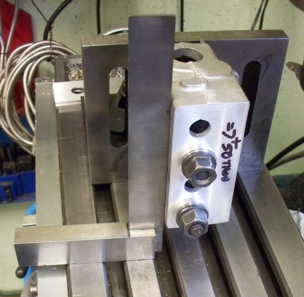
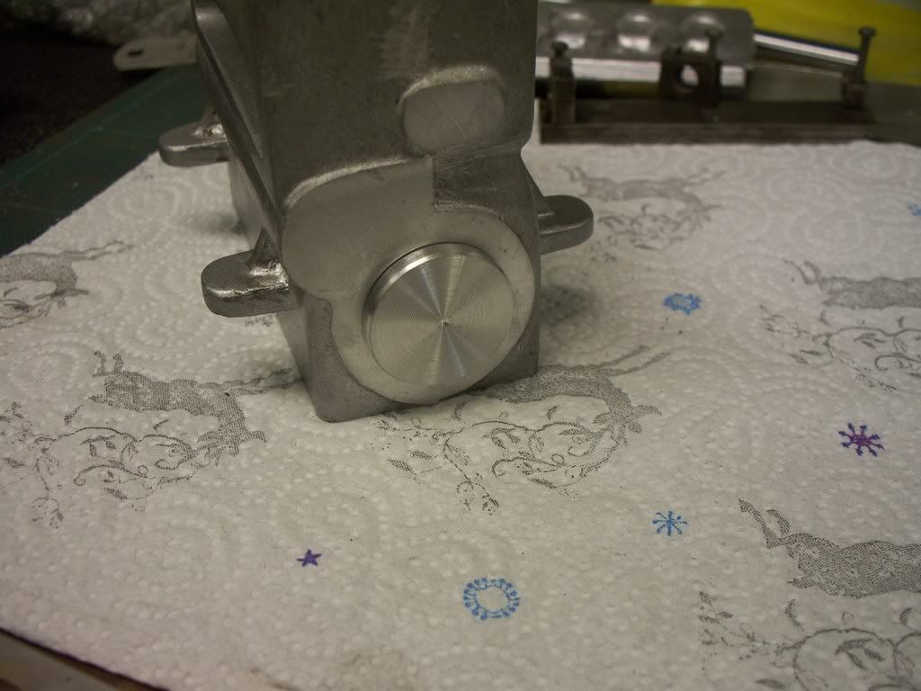
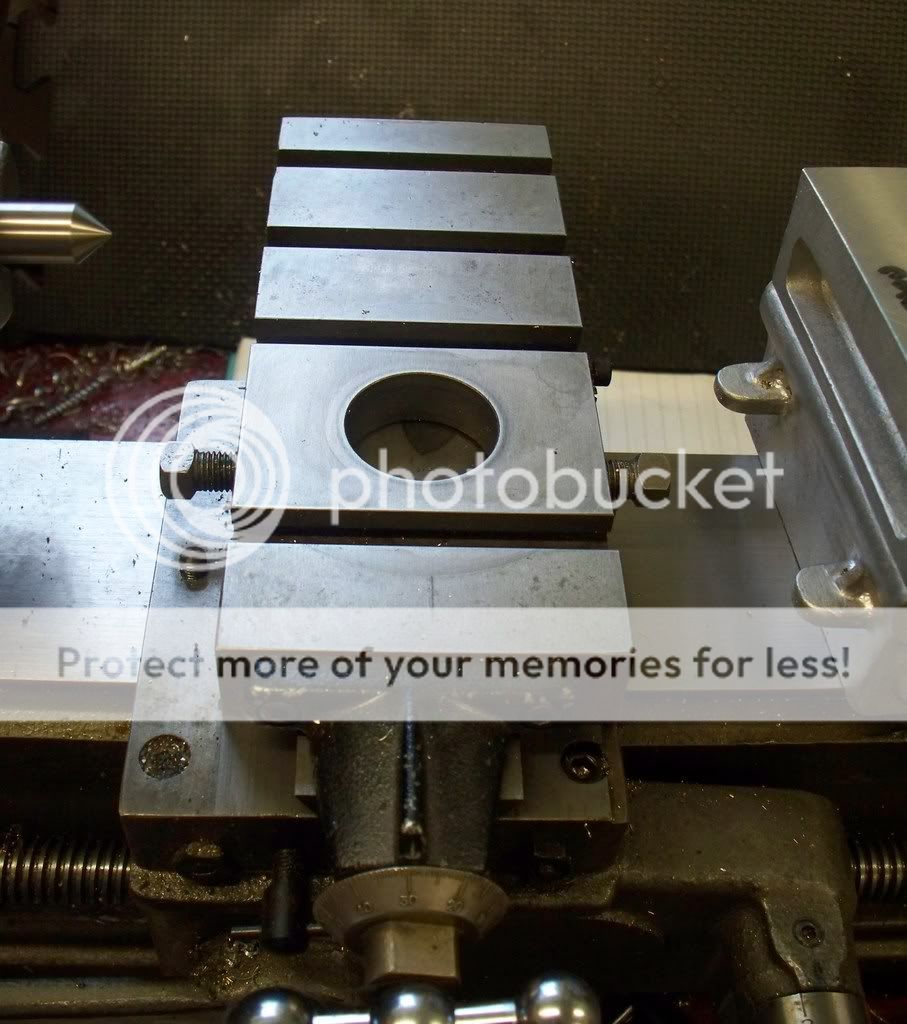
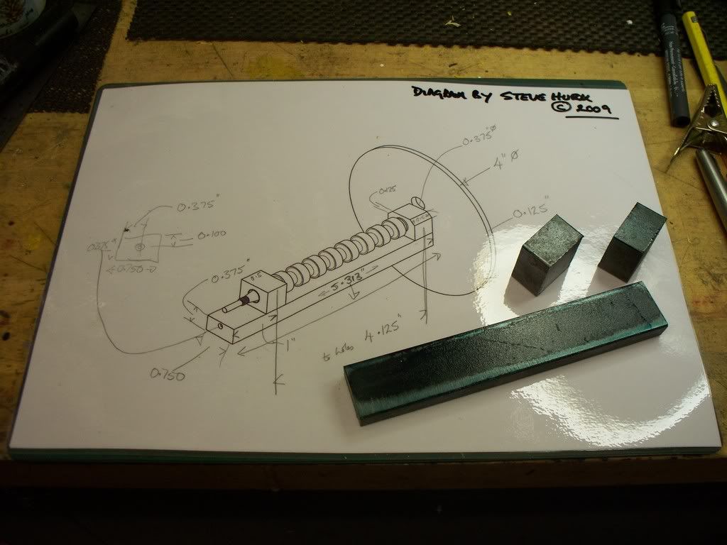
Today I only managed an hour or so, and decided I would clean up the two ends of the casting by mounting it on an angle plate (see photo). I made a couple of aluminium washers to protect the top of the block (although I have another 50 thou or so to take off -easy to make a dig or two). Using parallels to give space The top was soon cut to dimensions. the casting was then reversed and the same actions taken.

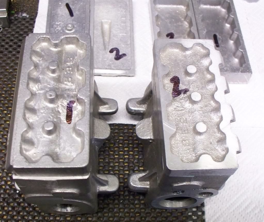
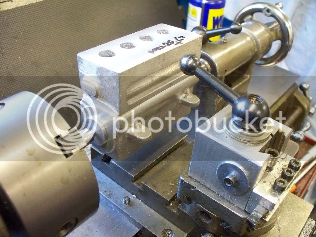
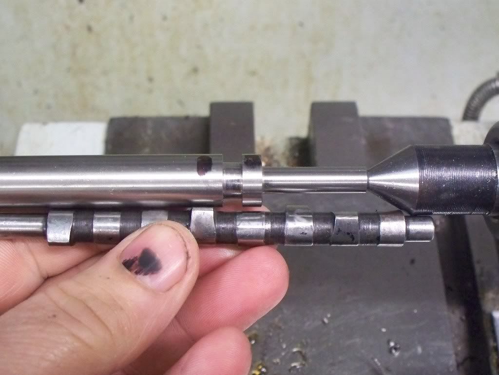
Now come a request for help or guidance. When checking the casting for overall length against the plan it was more than 1/4" too long still. You can see the difference with the unmachined cylinder head lain on the supposedly finishe block (only in length).

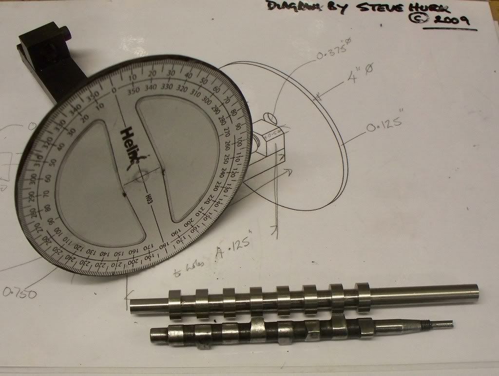
Now the question is, do I machine off one end to get the block to length and loose the shape of the casting end? (If I tooks some off each end I would loose the overall shape on both!) Or do I remove as much as I can whilst still retaining the shape, and then measure the difference between actual block and the plan, then making the extra onto the camshaft and crankshaft etc.

The second option is my favoured but am I letting myself in for more problems. I also have the difficulty of the block being bigger than some of its attacnments in width as well as length. i.e. the sump and the cylinder head (only in length).

I thought it better to raise the issue here and sleep on it before taking off metal that would be difficult sticking back on with blue tack!

Here are a couple of images.......

sealcylinderblock08012009009.jpg


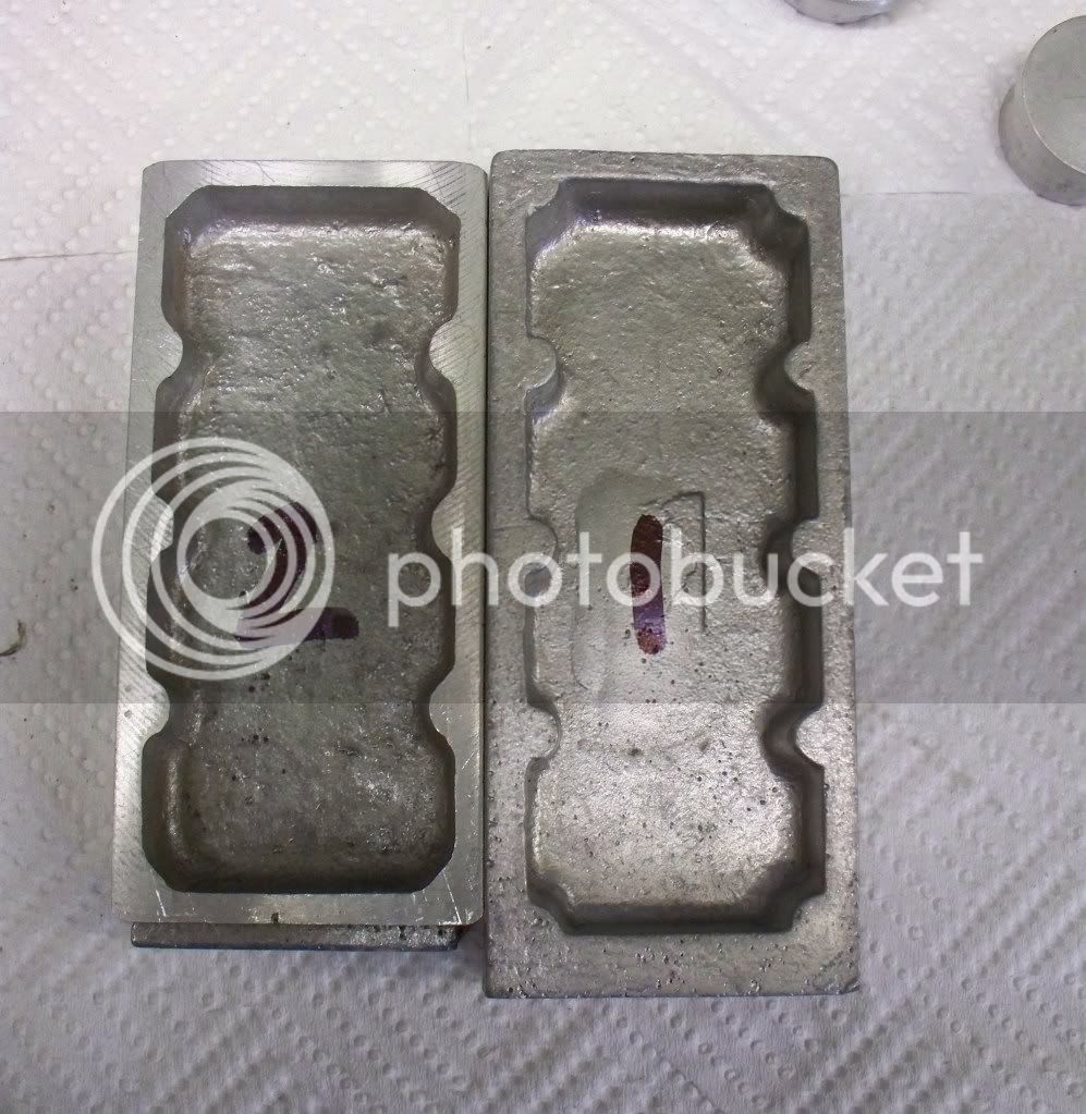
and the difference in castings......

sealcylinderblock08012009024.jpg


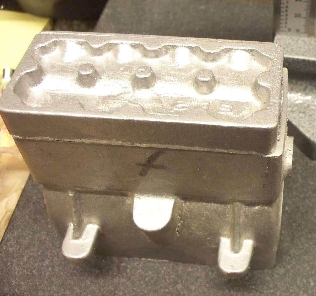
and finally................
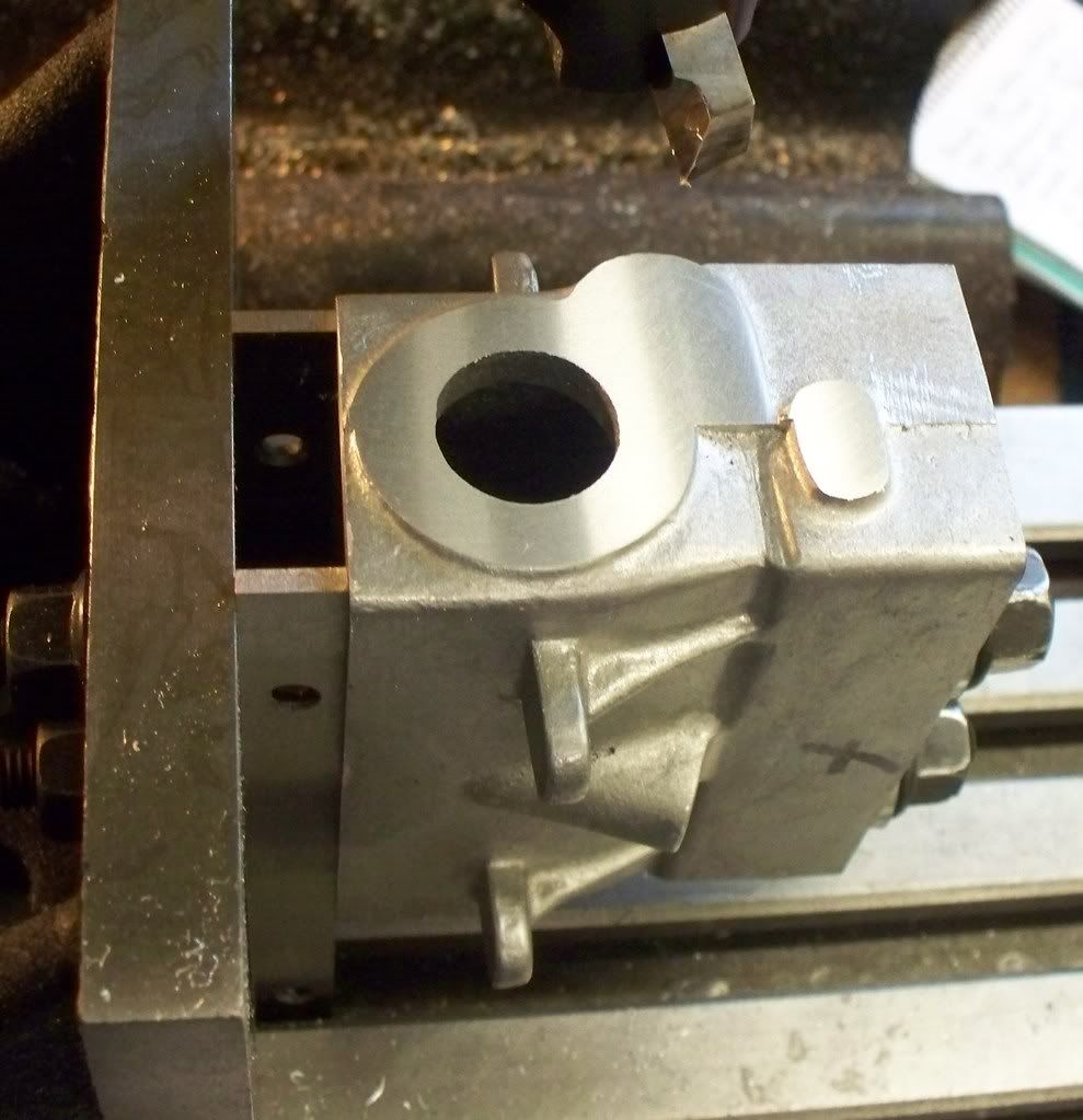
sealcylinderblock08012009012.jpg


Mike,

I assume the 3 bumps in the centre of the head casting and the bump at each end are for head bolts ???

If this is so, maybe it's an idea to determine how these line up with the block and set a central datum on both castings that maintain this relativity and the position of the cylinders, also from these central datums.

Hope this helps. ??? ???

Best Regards
Bob

 
Hello Bob, I was using the cylinder head to show up the amount of 'extra' casting I have with the cylinder block really.

Update today.

I needed to bore two 1 1/8th holes at either end of the main cylinder block casting on the Seal 15cc 4 cylinder engine. So it would be a simple job of bolting the block to the angle plate on the mill wouldn’t it? Well the first thing I checked for was the length of the longest boring bar, which of course was too short. Ok I would make one, a little more time but not a big problem. Just in case I thought I would check the amount of travel on the Z axis (downward travel) of my mill and yes, you guessed, not enough!

After a cup of tea and a ponder I decided I would have to use the method Edgar T Westbury himself used 62 years ago and bore the holes between centres on the lathe cross slide. So the tool post would have to come off. Something I had yet to do so it was with a little apprehension that I started to look to see how to do it. In the end it was quite simple. With the tool post removed the cylinder block was then put between the two centres using the blanks to position the casting (see photo below).

This allowed me to measure the distance between the base of the block and the top of the cross slide. The packing required was then sourced and some machining will be required to get it so the casting can be bolted down securely. That’s where I will be picking up the job next time.

seal10012009002.jpg


seal10012009014.jpg


seal10012009011.jpg


Today I managed to get back into the workshop and having received the camshaft fixture plans and the cutting chart from Steve Huck (thanks Steve) I decided to leave the casting I have been working on and return to making the camshaft.

The first job is to make the fixture and after locating the nearest sized steel, it was a case of squaring up the base and two upper blocks. It never ceases to surprise me how much time is spent in setting up compared to actually making swarf! I now I have to concentrate more than most and this must add some time, but it is still catches me out.

So the sum total of my work today is to get the base to size and the two upper blocks cut roughly to size. More work tomorrow will be required before the fixture is completed. I have time on my side however, as the material I was going to use, then harden, will not now be used. Instead I will be trying Steve’s recommendation of using silver steel (drill rod in the USA I believe) instead without hardening. Time will tell but Steve has built, and run successfully, several cams in his engines this way.

So I will need to buy some material for the camshaft. Between its arrival and starting to cut the cam lobes, I will go back to the main cylinder block and carry on with boring the crankshaft aperaures.


seal10012009017.jpg


Also I received some great service today from a supplier in the UK. Arc Eurotrade stock the bearinsg I need for the engine so I ordered them yesterday afternoon (Friday) and they arrived this morning! Now thats impressive!

seal10012009020.jpg
 
Nice build mike!

Keep it going! I was reading about your lathe challenge.....Hang in there!

Dave
 
Mike,

Good to see you back on the engine.

Where is the full and glorious technicolor video of the beautifully refurbished Myford ??? ???

Just Joking ;D ;D

Best Regards
Bob
 
Edgar T Westbury’s Seal 15cc 4 cylinder petrol engine – update 3rd March 2009

Looking at the plans as supplied I cannot get my head around the dimensions given regarding making the camshaft blank. Feeling a little under the weather I thought that the best way forward would be to make up a machining aide memoir and try and make sense of the drawing. Eventually I thought I was there and would check my dimensions against a broken camshaft given to me by the seller of the casting's set.

I intend to make two camshafts initially. The first from stainless steel and used to see if I can get away without hardening the shaft as recommended by one or two HMEM forum members. The second would be made from steel which I would subject to the powder hardening process. I fully intend to make other camshafts for this engine later on when trying to improve performance. I hope to learn a lot more about small/miniature cams and their performance over the coming years. Don't ask me why but the subject does ‘rock my boat’ as they say.

Anyway I chucked a length of ½” diameter stainless steel which measures 0.499” and since I am working to a tolerance of +/- 0.001” I will not take a surface cut. Because of the tolerance limit I have set myself I thought I would take time to check that the Turner lathe I have has the tailstock in line with the chuck. You may ask why I haven't done this before and the simple answer is lack of experience. I also believed (wrongly) that the accuracy would be as good as it got when leaving the factory so leave well alone, in case I mucked it up. Its only the rebuilding of the Myford lathe that has given me the confidence and perhaps techniques, to check something I should have done as soon as the lathe was received.

I have always suspected something could be out of line from some long cuts done earlier. When using 2 DTI’s to check alignment I couldn't believe it was over 4 degrees out over about 7 inches! The remedy was simplicity itself, with the tailstock moved to the correct position by using the adjusters, before being locked off. I decided to run the lathe up and move the saddle up and down a couple of times and recheck, finding everything now running true.

I kicked myself for not doing this earlier. If I am fortunate enough to ever buy a new milling machine I will carry out checks on everything before even switching it on! Fear of the unknown has a lot to answer for!

With the confidence that the set up of the bar was running true in the 4 jaw chuck and in line with the revolving centre in the tailstock, I set too turning down one end to the 0.250” diameter required. So I allowed enough over to clear the centre with the turning tool, then using the DRO, moved to what I thought would be the correct position to cut the gap between cams. All was going fine if slowly, until it came to cut the second inset, leaving the cam blank alone. Checking before I made any cut something did not seem right. I checked the measurement and compared them the broken camshaft and whilst the width of the cam was correct, the gap between them was not.

No matter how hard I tried, I kept tying myself up in knots. I got so confused that I gave up and decided to call it a day. It was only when laying down this afternoon that, by using graph paper to scale, I worked out what the dimensions should be.

Blonde moment over I have made a new aide sheet, so when I fell well enough to have another go, I should at least know where I have to cut!

I don't say I will get it right, but I now know what needs doing, the I thought the same this morning, so don't get too excited!

To be contd. :-\
 
Mike,

Why not make a test from free machining steel and the for real from drill rod which can be hardened without messing about with powder. ??? ???

It's easy to say and I hope it's helpful ???

Best Regards
Bob

Edit - In ETW's time they all seemed to be obsessed with hardening cylinders pistons cranks etc. - Like they were going to run for 100,000 hrs. For model hours I'm not convinced it's necessary but others may be better informed than me.
 
Gee Mickey, I'm sorry you had to go thru all that. If you had emailed me, I still have the drawing i made of the seal camshaft. I could have dimentioned it any way you wanted and sent you the PDF.

Hope all goes well.
 
Thanks Bob, your not the first to say about the need to harden. I just fancied seeing how it worked since I bought the powder 12 months ago and have never used it!

Steve, that's very kind re the PDF. Its more of a problem I had in the head rather than the plans.......today added to the 'learning' experience.......

I thought yesterdays brain clogging problems were over. However, whilst I managed to sort out the dimensions for the camshaft by use of graph paper, when it came to machining I was still unconvinced it was correct.

I thought I would help myself by marking, in permanent marker pen, the general location of the cams, so I could see if I was going wrong somewhere. In the event these marks caused me even more difficulty! I did a dry run as it were and ran through the sequence written on my notebook. Whilst it finished where it should, the gap between cam blanks seemed too large. So I got the defective camshaft (it broke in the middle) sent by a previous owner of the castings, and when comparing the marked out bar with the camshaft the spacing was fine, but the gaps seemed to large [see photo].

sealcamshaft03032009005.jpg


In the end I was so confused I just gave up and thought I would cut the cams as per my dimensions. You may have guessed that after cutting the first two cams everything was as it should be and the cutting of the remaining blanks went without a hitch. I do not know why I got so tied up with the layout (I suspect it’s my medication!!) but it was not only time slow, but also confidence sapping. I just didn’t believe my own workings and it didn’t even look right on the dry run but right it was. Some optical illusion!

After cutting the camshaft blank I did compare it with the broken camshaft and there is a little variation on the damaged camshaft which may have also disrupted my approach to the work.

My next session will entail making another cam blank but in steel that I will try and harden. I may also need it if I make a mess in applying Steve Huck’s cam turning technique. Now I have done the first blank I am sure the next one (and future camshafts) will be done much quicker. My aide-memoir worked even if I didn’t believe it and I will write it up properly, laminate it and put in the Seal box of bits for the future. I don’t want to got through the last couple of sessions again. No point in learning a lesson if you don’t remember it.

My next task was to stick the 360° paper template onto the cam turning fixture and then I called it a day. One surprise was the variation in dimensions on the broken camshaft.....and looking at it it had been in use....mind you it did break.........Hmmm.....

sealcamshaft03032009010.jpg


Metal Mickey said:
One surprise was the variation in dimensions on the broken camshaft.....and looking at it it had been in use....mind you it did break.........Hmmm.....

Maybe too brittle from the heat treatment. ??? ??? ???

Best Regards
Bob
 
Interestingly enough, Jerry Keiffer does not harden his camshafts. He makes them from 4340 and leaves them "soft". If you've worked 4340, you'll know it is not real friendly.

Dave
 
looking good mike............i had a chance to buy one of these engines half done and i turned it down thinking i would never finish it.......after reading about your build so far i now wish i had bought the engine...........oh well i can have fun reading about your build.

thanks for taking us along for the build.

chuck
 
Been a little unwell but back in harness now....

aermotor8 said:
looking good mike............i had a chance to buy one of these engines half done and i turned it down thinking i would never finish it.......after reading about your build so far i now wish i had bought the engine...........oh well i can have fun reading about your build.

thanks for taking us along for the build.

chuck

You never know when the next set of castinsg comes along....I bought these on an off chance although the engine was marked down for a future build when I had a bit more experience.....but when is that? So now must be the time? Hope you get another chance as it is a nice little engine. Hard to believe its 62 year old design!
 
The single 4 cylinder Westbury Seal engine is no longer a projet to fit a classic boat. No, instead I have purchased another set of castings and it will now be a twin engine with contra rotation props! Mad or what!

At last I felt well enough today to get back out into the workshop for the first time for a while. Nothing feels better than a successful or even semi successful session. It even gets better in that I was working on the Seal engine for the first time since the start of the Myford refurbishment.

It took quite a while to sort out the turning fixture for the camshaft with no parts fouling each other. I had to reduce the diameter of the front disc that registers the degree of rotation of the camshaft. Then there was a problem of getting the cutting tool to have sufficient travel without fouling anything. This all took time but eventually everything went around without anything going bang!

The cam blank I am using now was not made to match the fixture (my mistake) so I am going to complete the machining as a practice and confirmation piece. Confirmation that the process I am using will produce the correct camshaft.

To help me avoid mistakes (since I am cutting 6 cams at a time) I decided to mark which cam was which, on the offset turning fixture. This, together with the cutting charts produced for me by Steve Huck’s meant I had a chance of cutting the right cams in the right order. As an added safety measure I also marked all of the cams with a permanent marker. If those cams which had to be left remained covered with permanent marker ink, I wouldn’t have a problem!

sealcamshaftturningvideo25032009012.jpg


For those of you who have read Steve’s cam article in both Model Engineering in the UK and Model Engine Builder in the USA you will realise that ‘the first cut is the deepest’, as the song goes. Initially I need to remove 0.078” from all the Cam blanks, but in order. After that it’s a case of revolving the camshaft by 5° and making the cuts on the chart. I had printed out a set of charts already and filled the x boxes with a highlight colour then laminating them. However I decided to print off a new set and use a highlight pen to colour in the section that was being cut, so I could keep count.

I need this amount of organisation since there are 47 rotations with cuts for the exhaust and 49 rotations and cuts for the inlet cams. So as you can see there is a lot of work to be done. Now multiply that by the 3 cams I will be making (this practice one then two engines) and you will see this is not going to be quick!

More importantly though is the fact that I’m back!
 
Mike,

Good to see you are back on the job and the time spent getting organised for your cams I am sure will pay huge dividends doing the cuts. :bow: :bow:

Best Regards
Bob
 
Looking Good Mickey!

I Wish I was that organized! ::)

Dave
 
Today I managed to get the practice cam turned enough to satisfy myself that the system will work so a start has been made on the first of the two real camshafts.

I was hoping to make faster progress but I got distracted by the arrival of another set of castings. When inspecting them I was very surprised to see quite a bit of difference between them. My first set always seemed a little out, especially the cylinder block and head

camshaftturning26th032009014.jpg


Seeing the second set has confirmed that the size difference is not the same with the second set. Also the sump casting is a lot bigger compared to the rest of the first cylinder block and hen comparing the two sump castings (photo) you can see just how much difference there is.

camshaftturning26th032009015.jpg


I don't know if there is another supplier of castings for the Seal other than Hemingways, [link]but if they come from the same source there must be another set of patterns! At least I now know the differences between the both sets and what work I have to do to put them right.
 
Looks like they came from different paterns, on the sump the corner fillets are diagonal on the left and radiused on the right. Also the webs on the mounting lugs are different, one curved one straight.

I'm not sure how long Hemingway have been doing them but they may have been part of the range they took over from Woking Precision Models.

Jason
 
Back
Top