Drilling steam cylinder passages

Home Model Engine Machinist Forum

Help Support Home Model Engine Machinist Forum:

This site may earn a commission from merchant affiliate links, including eBay, Amazon, and others.

Mainer

Senior Member
Joined
Oct 10, 2008
Messages
578
Reaction score
20
Someplace, a while ago, I saw a description of a bang-on, never-fail method of aligning a cylinder for drilling the steam passages. Does that ring a bell with anybody? I've searched this forum, and also the HSM forum, but not found it...either because of faulty searching or because I saw it someplace else.

I'm just starting ET Westbury's "Unicorn" engine.
 
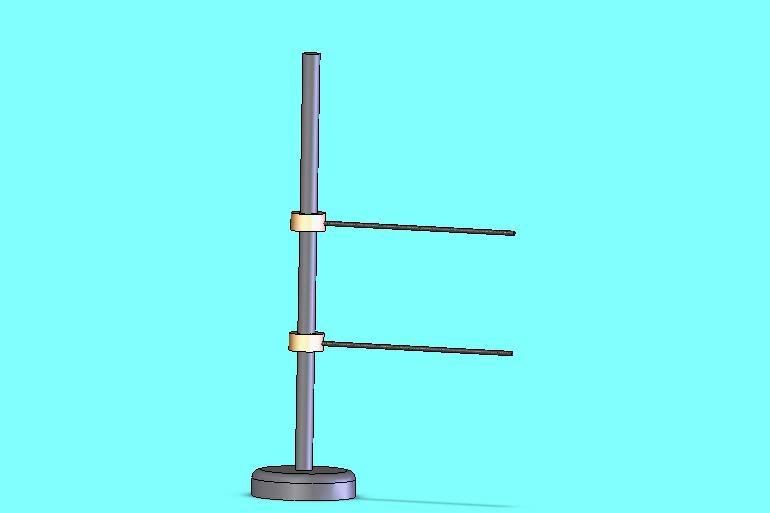
Verticle post with two sliding pins some thing like a tall letter "F". If both pins are the same length and can slide up and down the post its a simple matter to set the cylinder block up in the drill press or mill. All you do is let the top pin just touch the outer cylinder edge and the second lower pin sit in the inlet port at the right point for the drill to break through. Rotate the cylinder untill both points line up and you know the drilling for the steam port will be correct.

 
Thanks -- I don't think that's the technique I'm remembering seeing the description of, but it sounds as though it ought to work really well.

(Or maybe it IS the technique I saw described before, and I've just got a really bad memory...!) :eek:
 
Hi
Iv used the same tool for 30 odd stes of ports on most of my traction engines and my locos. The rig I have is a 1 foot length of 1/2 inch silver steel rod mounted in a 3 inch disk of cast iron that sits on the miling table. The two fingers are 1/8th silver steel about 6 inches long ground to a point and silver soldered into mild steel collers that are grub screwed to the 1/2 inch columb.
As a rule i can say that the drillings will come through with in 5 thou of the desired depth in the steam ports on in the valve face.
 
compound driver 2 said:
Verticle post with two sliding pins some thing like a tall letter "F".
Can you post a picture for those of us that are imagination challenged? :)
 
I second DB's motion - 'aving trouble gettin' me 'ead around that one.
 
Me 3, I have had my second coffee, and I still andn't picture it.
Regards,
Gerald
 
It lets you locate the desired entrance and exit points for the steam passage on a vertical line, which will then be the line the drill will follow.

(That probably didn't help any....)
 
drilljig.jpg


The two pins slide up and down the centre colum, both pins are the same lengthy. If you rotate the cylinder block untill the top pin touches the lip of the cylinder bore then slide the bottom pin up so it touches in the steam port slot you know its a verticle line between the port and the cylinder lip.

Il try to take a photo Monday when I get back into the shop.

I hope the cad drawing makes some sense
 
Success! Thanks to Compound Driver 2. I didn't use that exact setup, but I used the concept. I put a piece of wire bent at 90 degrees in the drill chuck, then by raising and lowering the quill and moving the X-axis I probed the entry and exit points for the passages with the cylinder held in the milling machine vise. It took a lot of trial and error in positioning the cylinder to get the X-axis reading the same for entry and exit -- I'm sure CD2's device would be faster to use -- but the bent wire worked and the drilled passages are lined up better than I had any expectation of.
 

Latest posts

Back
Top