drafting symbols - what does this mean?

Home Model Engine Machinist Forum

Help Support Home Model Engine Machinist Forum:

This site may earn a commission from merchant affiliate links, including eBay, Amazon, and others.

zeeprogrammer

Well-Known Member
Joined
Mar 14, 2009
Messages
3,362
Reaction score
13
I'm looking at a drawing - at a symbol I've never seen before.

I was top of class in drafting - but that was 40 years ago. (That's right - pre-cad). And...I've only started machining a few months ago...so my knowledge is both old and limited. Okay, I'll say it, near non-existent. (Now show me a schematic and I'll say...yep...that's what it is...a schematic.)

In any case...

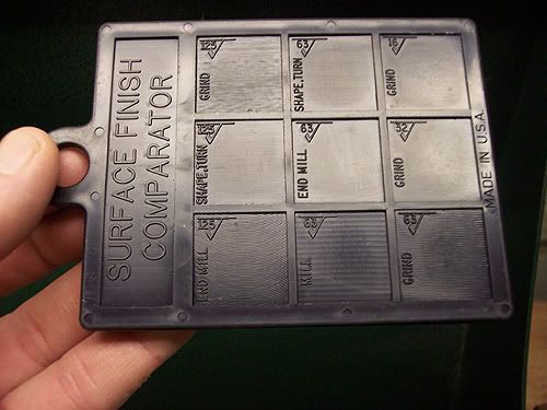
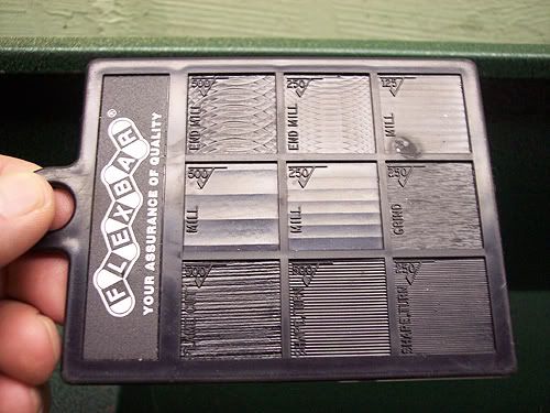
The symbol looks like a large check mark (or V with one leg shorter than the other) with a number inside. One shows 32 and another 64. The part I'm looking at is the crankshaft for a launch engine. (Basically a rod with a disk on one end.) The symbol with the 32 is on the rod while the 64 is on the disk. What do they mean? ??? I'm thinking tolerance but it don't make sense to me.

While I'm here... the diameter of the rod (shaft) is called out as:

.2183 DIA REF. - SLIT FIT
.0005 CLEARANCE WITH DET.
#3.00.040-01 & 3.00.020-01

I'm thinking 'SLIT FIT' should be 'SLIP FIT'?

I get the .2183 (and good luck getting .---3).

And sorry to keep demonstrating my ignorance (maybe I shouldn't have had the wine...but it's Friday night)...I'm now confused about 'REF'. Help. ??? (And don't just tell me 'reference'....and at least one of you won't be able to help themselves. ;D)

0.0003 hahahahahahaha...that's rich...hahahahahaha...like I can do that...hahahaha
I'm happy if there's metal left when I'm done.

Thanks.

No. No machining tonight. Long week. Wine was more medicinal than anything else. (Sure. Sure.)
 
That specifies the desired surface finish in micro inches. That symbol was probably there 40 years ago, but may have slipped away. They make gages that give an example of the various finishes called comparators, basically you drag your fingernail across the standard, then your part and compare them. Kinda like "scratch and sniff" which is another name for the gages. I like to think of a 125 finish as kind of your average milled finish, a 250 is a saw cut and a 16 probably has to be ground to achieve although you can come pretty close with the right combination of insert and hard material. They also make profilometers that drag a stylus across a part and measure all the little peaks and valleys and come up with a number, but doubt you will find too many of them in a hobby shop. I'm sure if you google surface finish, you will find more then you ever wanted to know.

Brian
 
Those are Surface Finish marks.
A 32 RMS finish is very smooth.
A 64 RMS finish is even smoother, like glass...

At work we use an electronic profilometer to measure surface finishes.
One night a few of the young guys decided they should try it on my
bald head to see just how smooth it was. I did sit still for that and
found out that the top of my head was a 30 RMS Surface Finish.
Then one of them suggested polishing it up with some Scotch Brite
to see if they could improve the reading.
I RAN!
Rof}

Rick
 
Thanks Brian and Rick.

What does one do to achieve the specified surface finish? Get one of them profilometers or grow my nails out and test and polish? Do hobbyists typically try to achieve that? Or would the hobbyist say 'hm...looks like it needs to be pretty smooth'?

Rick...for the pate you need a very very soft and fine cloth...then find a professional shoe shiner. They'll fix you up and it'll feel great. A little music and you got entertainment. Slappity slap slap. Go for it. Friends will appreciate it. Saves them from hunting up a mirror. Just don't let them breath on it and try to rub the smudges off. Rof}

 
Hey Rick,

You might wanna check your figures, typically smaller numbers mean smoother.

Brian
 
An electronic profilometer runs about $1500.00
OR, you can buy an old school finger nail scratch gauge for
about $9.00 This is a photo of mine.

SurfaceFinishComparator1.jpg


SurfaceFinishComparator2.jpg


It can be found here:
http://store.flexbar.com/merchant2/...duct_Code=16007&Category_Code=Surf-Rough-Comp

You are correct Brian.
Smaller numbers are finer finishes.

Rick
 
Rake60

You may want to check your post... The smaller the number the smoother the surface. Did you succeed in improving the finish? ;)

As far as what a hobbyist can do...

There is a chart in Machinist Handbook called "Surface roughness produced by common production methods" on page 708 of the 25th edition big book. 64-32 Ra is in the range of Turning - Boring though on the smoother end of the range. A good turned surface finish should be within the range of most machinists capabilities.

If you want to be more sure. Most tool suppliers offer a surface finish plaque standard for machining operations (they are made for injection molded finishes as well). A rub with a finger nail on the plaque and across the machined surface will tell you if you're in the ballpark. That and a look with an eye loupe will get you pretty close.


Marinesteam
 
Yup, theres the "scratch and sniff" gage. To answer the question about achieving the finish in the hobby shop, thats where emery cloth comes in. In the manufacturing world, you never wanted to call out a smoother finish then needed since it generally gets more expensive to create it. In the model world where "bling is king" the rules are different. I have had hydraulic cylinder rods that were too smooth and wouldnt hold an oil film, causing excessive seal wear as well as "stick slip" while moving, so you can over do it.

Brian
 
Don't underestimate the "scratch and sniff" gauge. ;)
An average piece of paper is .0023" thick.
Hold it flat on a table, close your eyes and run your finger over the
edge of it. It feels a whole lot thicker than 0023"...

Rick
 
We used "Rubert blocks" for years until hand held surtronic machines were available.There must be thousands of sets of these kicking about in old workshops.They still have a website at... www.Rubert.co.uk
Different sets for different machining operations,although I seldom see any indication of required surface finish on model engineering drawings.

best regards Steve C.
 
ZP:
I think your question was pretty well covered. I will add enco also sells metal surface comparators both import and Gar an American standby brand.
I also have one of the plastic ones. For the hobby shop the plastic is likely more than adequate.

Import $32.95

Gar $70.95
My wife found a Gar on e-bay for me.
Tin
 
te_gui said:
I have had hydraulic cylinder rods that were too smooth and wouldnt hold an oil film, causing excessive seal wear as well as "stick slip" while moving, so you can over do it.
Brian

I wanted to illuminate Brian's sentence a little (quote above)...for newbies like me. It's not obvious that this can happen. (Not that someone like me can get something that smooth yet.)

Thank you all. Very helpful information.
 
Having work in the Plastic and steel die industry, I am very familiar with surface finishes.
Here is a simple trick to help you.
When you machine a part, it produces a "grain" with the cutter. With a milling cutter, you get many arcs, laid next to each other. For Lathe,Planner, or grinder work,you get furrows, like a plowed field, or single cut file.


Now, at 32 or better (<32) (smoother) you cannot define "grain with your finger nail.
That's right, just drag your finger nail across the work , in several directions, and see if you feel ANY difference.
Close your eyes, as you may subconsciously affect your feelings.
If you fell anything, like a drag or a groove ,or harder to move in one direction and not the other, it is not a 32 !

You don't need a profilometer to tell you
Remember any direction feels the same !

Rich
 
Thanks Rich.

It turns out one of our mechanical techs at work is a certified machinist. I don't think he's that experienced...but he's certainly much more than I am. I'm going to take some parts into him and see if he can help too.

My last part (last part is always the best...right?) seems nice in three directions. Hard to tell in the fourth. It was milled brass. So we'll see.

Thanks again.
 
Z: do not worry too much here. Just make it a smooth fit. If you are balding like Rick just scratch your head then the part if they feel the same you are good to go. If yo are luck enough to have a full head of hair compare it to some other known smooth skin. Like it was said earlier most Model drawings do not have the symbols to confuse you.
Tin
 
Z:
Well if the wife is out of town and no grand kids available you better invest in a surface comparator!!!!!
Tin
 
What does Ref mean.
In mechanical design we are not to dimension anything in more then one way. (From one end to the hole, from the hole to the other end, and the total length is bad form. Each dimension carries a tolerance and tells the maker of the part what is important.

BUT some times the stack of dimensions gets so convoluted that it is a kindness to put in a REF dimension. It means You might like to know this but I will not check it and it is not the dimension that controls how it is built.

One example is dimensioning of the start and end of a slanted surface and a "Ref" of 60 deg.

Or, I think you are using CNC so here are the centers of the radius (REF.), but what I really care about is this surface.

Frank
 
Back
Top