Crank counterweights

Home Model Engine Machinist Forum

Help Support Home Model Engine Machinist Forum:

This site may earn a commission from merchant affiliate links, including eBay, Amazon, and others.

Putt-Rite

Well-Known Member
Joined
Jun 12, 2013
Messages
56
Reaction score
7
Location
Haverhill, Massachusetts, USA
How are crank counterweights figured? Do you weigh the piston, piston plus crank, a percentage thereof, or just eyeball it (I prefer calibrated eyeball).;D
 
According to an old book on single cylinder engines, the counterweight is the sum of the following weights: weight of crankpin , 3/4 weight of rod, 1/2 weight of wristpin, 1/2 weight of piston. The center of mass of the counterweight must be the same distance from the center of rotation as the crankpin and diametrically opposite the crankpin.

RWO
 
enginebalance.jpg


Here is a machine-shop way to balance a single cylinder engine:

Weigh the small end of the connecting rod, and record this value as reciprocating mass.

Weigh the large end of the connecting rod, and record this value as rotating mass.

Note: the small-end rod weight, plus the big-end rod weight, should equal the total weight of the rod. If it doesn’t, retake the measurements, as you did something wrong.

Add up the weights of all “pure” reciprocating components (i.e. the small-end of connecting rod, the piston, rings, wrist-pin, etc). Divide this number by two.

Take the above number (which is equal to half of all reciprocating mass), and add it to the weight of the large-end of the connecting rod (the rotating mass). This number is the final equivalent mass that must be balanced out by the crankshaft.

Machine a cylinder on the lathe that weighs the same as your equivalent mass, as calculated above. Be sure to include a small eye bolt for attaching string, or dental floss.

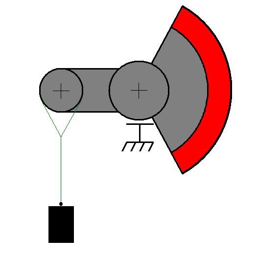
Manufacture your crankshaft with oversized counterweights (because it’s easier to remove metal than it is to add it). Suspend the crankshaft on a set of machined parallels. Ensure the parallels are perfectly level and free of debris – as the crank must be able to roll freely with the smallest of effort.

Attach the equivalent mass to the crankshaft’s connecting rod journal with some small string, or dental floss. The rod journal’s line of action must be parallel to the supports, and perpendicular to the string (as shown). The string must be perfectly in-line with the center-axis of the rod journal. If the string is off-center, is will introduce significant error.

If the crankshaft rotates clockwise, machine away material from the red area of the crank, until there is no rotation.

If the crankshaft rotates counterclockwise, you need to add material to the red area of the crank, until there is no rotation.

Remember that a “very small” rotation is still a rotation.

The engine is balanced when there is “no” crankshaft rotation. When you get close, you can drill holes in the counterweights to “sneak up” on the final mass, in lieu of lathe operations where you can overshoot.

This method will provide more than adequate results, and permit you to run a neutrally balanced flywheel - - - in a single cylinder engine. . . .
 
Nice entropy,thank you Puttrite for posting this question... I was wondering myself.
 
Entropy455's method produces a staticly balanced crank, but ignores the unbalance forces caused by the reciprocating components. If you want to minimize engine vibration, you must add additional weight to reduce the effects of the reciprocating masses: rod, piston and wrist pin. It's impossible to completely eliminate the forces caused by reciprocating masses with rotating masses, but it is possible to reduce them by approx. 50%.

RWO
 
The procedure does include reciprocating mass.

In a single cylinder engine, there will always be some degree of non-linear dynamic loading that varies with crankshaft angular displacement. When an engine is poorly balanced, these dynamic loads become significant. Steel components fatigue, aluminum components strain-harden, and bearings take a beating.

It is possible however to achieve a best compromise – i.e. a balance job that minimizes strain loading from the non-linear dynamic loading. The idea is to spread out the inherent out-of-balance condition over 360 degrees of crankshaft rotation. The procedure I listed above, while crude, does just this.

The method is very effective at achieving a near-ideal balance within a single cylinder engine. If one were to attempt dynamic balancing of a single cylinder engine, the best-achievable balance job will still be obtained using a counterweight sized with the "static" procedure.
 
Sorry Entropy455, I didn't read your post carefully enough and somehow ignored the first part of your post. I apologize.

RWO
 
Okay so work hardening of alum. helps to understand why rods break in race cars.

Now I'm looking for a used college physics book to read up on how to get my datum points my piston rods.

Cox mentions in the Hoglet plans something about arranging the rotating/reciprocating masses so the motor tends more to vibrate front-to-back rather than up-and-down.

Expanding from single to multi cyl. engines, what changes? What does one need to know?
 
i have ? If you balance like you say should you not balance first the crank ect then do your calculations and add your wiegts.
in my head you should balance the crank first. sorry just thinking whats in my head.......
 
The weight of the crankpin is assumed to statically balance the crank. Then the other weights are added to reduce the effects of the reciprocating parts.

RWO
 
The weight of the crankpin is assumed to statically balance the crank. Then the other weights are added to reduce the effects of the reciprocating parts.

RWO

oh i see ok cool thanks;)
 
Back
Top