Craftsman 109 Lathe

Home Model Engine Machinist Forum

Help Support Home Model Engine Machinist Forum:

This site may earn a commission from merchant affiliate links, including eBay, Amazon, and others.

Foozer

Well-Known Member
HMEM Supporting Member
Joined
Nov 26, 2008
Messages
1,181
Reaction score
83
Location
Camano Island, WA
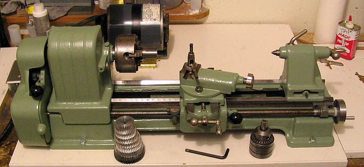
Here that a few of these are hidden away behind work benches and other objects long forgotten.Been described throughout the range of "Cute" to "Boat Anchor" But its what I'm stuck with and if it can turn out a Rocker Motor I'll slide it toward the "Cute" category.

So I have the 109-20630 model, sleeve bearing head stock and all. Have most of the change gears and the threading dial gizmo. Changed the motor over to a treadmill variable speed DC type and am very happy with the results.

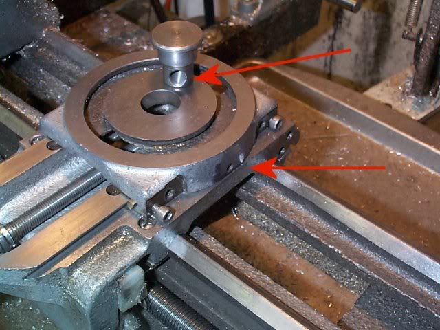
So now that the "Rocker Fever" has passed its time to fix some of the little things that need attention. First off is the cross slide. Time to get it into a smoother operational condition, has yet to be seen.

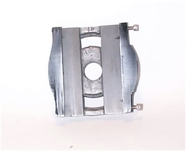
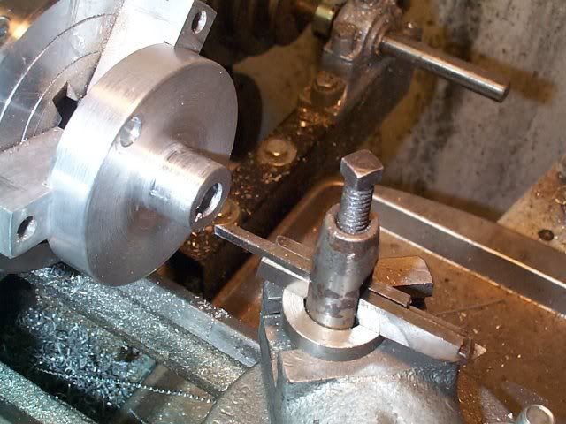
Original gib plate is steel, just doesn't like to slide as well as I'd like. Using a vertical slide to fly cut stock just plain gets hard on the fingers. Loosen the gib to ease the turns and well, that don't work. So cut one out of brass, its natural slipperiness ought to help some.

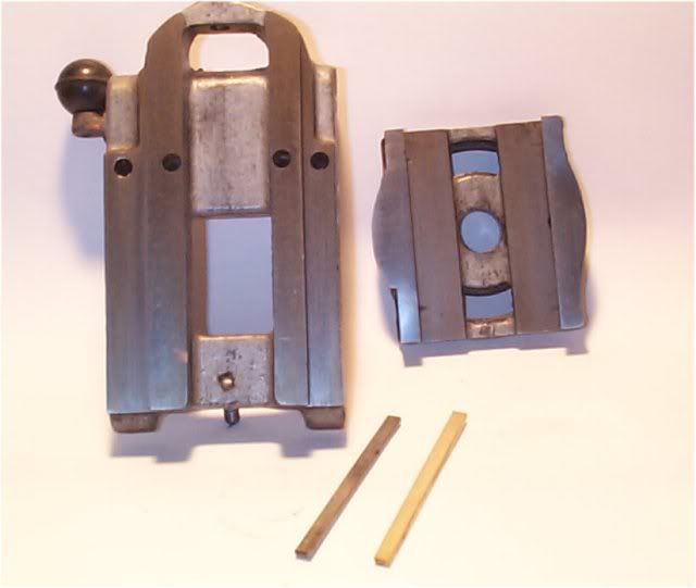
Before that, I spent some time with some 600 paper on a piece of glass and ran the separate components over it a bit to identify and knock down any high spots. Not looking to remove metal, just enough back and forth to get a consistent shinny surface. Then some Bon-Ami and oil mix, more back and forth till it felt decent. Enough for today.

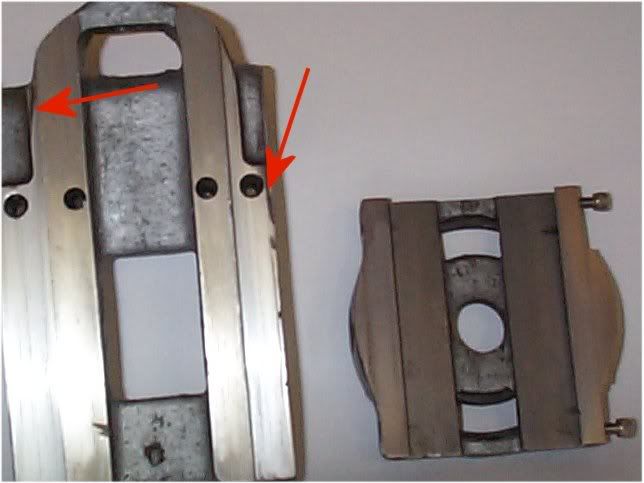
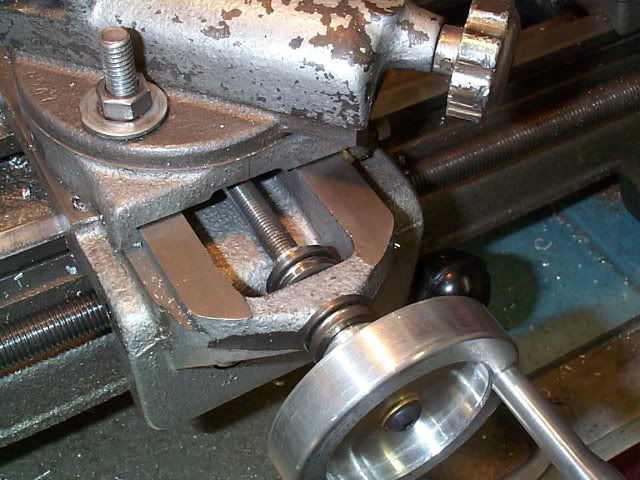
Next is the addition of another screw for gib adjustment. It only has 2, one at each end and at extreme travels the ends sorta hang out in mid air. That can be improved.

aa109-a1.jpg


Robert
 
I picked one up at an estate sale pretty cheap. I added the third screw also. Replaced the rear carriage gibb with one made of brass and moved the contact points to the outside rather than the single center point. Then drilled and tapped for two adjusting screws. One on each end rather than the wing nut in the middle. Helped stop the rocking of the carriage. Machined a new rear spindle bearing. Removed the pin holding the knob on the compound and installed a steel collar with a set screw so I could adjust it. Replaced the crank on the cross slide with a knurled knob and again put a steel collar on it with a set screw so the lash could be adjusted.

It won't replace my Atlas 12" but after tightening everything up it made some fairly good cuts. It will cut 1" steel with a HSS tool and take .018 cuts without complaining. It does OK if I don't push it hard. Does require some effort to get it tight enough to work properly.

Not quite a boat anchor. Nice thing is that it is really easy to move and small enough to put on a shelf when it is not used.
 
black85vette said:
I picked one up at an estate sale pretty cheap. I added the third screw also. Replaced the rear carriage gibb with one made of brass and moved the contact points to the outside rather than the single center point. Then drilled and tapped for two adjusting screws. One on each end rather than the wing nut in the middle. Helped stop the rocking of the carriage. Machined a new rear spindle bearing. Removed the pin holding the knob on the compound and installed a steel collar with a set screw so I could adjust it. Replaced the crank on the cross slide with a knurled knob and again put a steel collar on it with a set screw so the lash could be adjusted.

You do know the machine :) Sounds like my "To Do List"


Robert
 
I'm following along with you Fooz', in the interest of perhaps doing some mods to the 109 that I have. For those of you not familiar with these machines here is a picture of what one looks like so that you may better understand what Fooz' and others are talking about. They are terrific small machines and many are still around in use. This one was used all of its life in a auto atore to turn armatures for generators etc. My Father picked it up for a few dollars and gave it to me. I in turn, took it apart and cleaned it up and what you see is the end result. I just need to get a manual for it as well as a motor and I'll be all set.

BC1
Jim

109 lathe 2.JPG
 
I also have a 109, model 20630, besides a couple of other lathes. I've done most of the things described here, plus some. The people who say it's a boat anchor probably just don't know how to listen to the machine. It's not a Heavy 10, and can't be treated like one.

After making a rear bearing, buying a new front one, making a spindle nose adapter that will take a good chuck, replacing all the gibs with brass, putting in a third gib adjusting screw on the cross slide and some proper adjusters for the carriage gib, this little lathe works just fine. It's over 60 years old and it just needed a little fixing up.

You can see my 109 adventures on my Craftsman AA pages;

http://www.deansphotographica.com/machining/projects/109/109a.html

17.jpg
 
bearcar1 said:
. I just need to get a manual for it as well as a motor and I'll be all set.

BC1
Jim

I just used the motor from my bench grinder with a 2" pully and screwed it down to some MDF with the lathe as a test set up.

I have a parts list and a bunch of materials from different sources on the web. I will forward anything I have by email.

Dave; I like the chuck mount project you did. I bought an adapter from Littlemachineshop that allows you to use any of the 7x10 lathe chucks on the 109. Since I had a 3 jaw, 4 jaw and face plate the $18 seemed cheap for the adapter. I just had to get it square, face it and then trim it to fit the back of the chucks.

 
Deanofid said:
I also have a 109, model 20630, besides a couple of other lathes. I've done most of the things described here, plus some. The people who say it's a boat anchor probably just don't know how to listen to the machine. It's not a Heavy 10, and can't be treated like one.

After making a rear bearing, buying a new front one, making a spindle nose adapter that will take a good chuck, replacing all the gibs with brass, putting in a third gib adjusting screw on the cross slide and some proper adjusters for the carriage gib, this little lathe works just fine. It's over 60 years old and it just needed a little fixing up.

You can see my 109 adventures on my Craftsman AA [pages;]


Not a heavy for sure. Bent the first spindle, replaced it with one that had a 3/4 16 nose already cut into it. Allows for the Taig chuck to be mounted. That in itself was a vast improvement.

Don't worry I've gone over every detail of your "109 Adventures" and plan on stealing err, utilizing your ideas.

Posted by: black85vette

I bought an adapter from Littlemachineshop that allows you to use any of the 7x10 lathe chucks on the 109.

Also went that route. Worried a bit about how far past the spindle bearing the standard chucks (also from LMS) were. The cantilevered force seemed a tad to much. I did bend a spindle or two before the :wall: set in. The Taig chuck brings the work a lot closer to the bearing. Havent bent a spindle since.

Robert
 
Spent some more time with the cross slide. Good, but its pushing 100 degrees here today, and for this part of the globe that's a heat wave. Playing with some water and wet/dry paper seemed like a reasonable thing to do.

used a magic marker to see what the high low spots were. part looks smooth but the marker tells all

aa109-a2.jpg


Some low spots, Chasing my tail but ran the part over 220 grit down on a piece of glass. Kinda a back and forth routine. Sand a little, check with marker etc. Soon enough the point of diminishing return occurs and its called good. Marker up the mating piece, snugged the gib and ran it from one end to the other. Not really much of an improvement in the action from the earlier, but does show an improved contact area. Couple spots still low, I can live with it.

aa109-a3.jpg


Small binding? increase in force occurs at the far forward end of travel. Best I can measure the width shows the dovetails are about 0.002 wider at one end than the other. Thought about trying to whittle that down but decided I'd probably hose it up, so leave it be for now.

Robert
 
Yeah, the cross slide on a lathe tends to wear faster where it's most used. So the dovertail is probably a tad wider at the back extreme. Now, if you had a mill, you could take care of that... :'(

Chuck
 
cfellows said:
Yeah, the cross slide on a lathe tends to wear faster where it's most used. So the dovertail is probably a tad wider at the back extreme. Now, if you had a mill, you could take care of that... :'(

Chuck

Its on the list, 6 more months and I meet the 2 year bit on property conversion, no capital gains :) So what Uncle SAM doesn't get, some vendor will.

Couldn't leave it alone, so spent an hour or so with some 220 grit stuck between the slide and dovetails. Worked the tight end a bit. I know it taint exactly the way to do it. Did free it up a bit and I'd really better leave it alone for now while I'm on the good side of bad.

I'd hate to see what a good one feels like, ruin my whole conception of "Not Bad"

Robert
 
Looking good. I didn't do that much work on the cross slide. Just enough to clean it up and make it smooth.

Here is a picture of my cross slide. I turned some spacers and replaced the slotted screws that adjust the gibb with some hex set screws and then put a locking nut on them so the adjustment would stay put. Had to add the spacers because the nuts were dragging on the top of the carriage. I added the nuts to the compound front and rear screws but not the new center one. It would have hit the nut holding the compound in place.


IMG_1358.jpg
 
These old lathes seem to be popping up from the deep dark :)

Goofing off past few days, watching the hydro races today but did get another little irritant crossed off the list.

Cross Slide feed screw. BLAH! source of play, may not be able to kill it all but should be able to reduce it.

Had some thrust bearings, had used em before but never really finished it. Needed a new hand wheel, for some reason I just avoided making one.

So the bits and pieces. Took the original screw shaft and added a cross pin to hold the inboard bearing retainer, bearings are 0.375 id and shaft is 0.312 od. Made outboard retainer and drilled tapped outboard end of screw for a 10-32 hand wheel retaining bolt.

crossslide-a1.jpg


Thinking the retaining bolt wouldn't prevent the hand wheel from rotating on the shaft i tried cutting a little slot into the wheels id.

Used an eighth inch tool bit and feed it into the bore shaving a bit at a time. Took a while but got what I was after, a little pin protruding from the shaft slips into the slot, that'll get it from slipping on me.

crossslide-a2.jpg


Put er all together, snugged down the retaining bolt to preload the bearings for a gentle drag. Time will tell :)

crossslide-a3.jpg


Would of liked to of added some sort of bearing shield but the OD of the bearings just clear the slide as is. Case of having cake, but cant eat it..

Robert
 
Again you out did me. I made a new cross feed knob also but just put a steel collar on it with a set screw. I put in a feeler gauge snug everything up and tighten the set screw. Took almost all the play out of the cross slide.

Nice job on yours!
 
That new handwheel and bearings are a good addition, Robert.
I like this method of keyway cutting, too. A good way of doing things for us "under funded" machinists who don't want to pop for a broaching set.

Dean
 
black85vette said:
Again you out did me. I made a new cross feed knob also but just put a steel collar on it with a set screw. I put in a feeler gauge snug everything up and tighten the set screw. Took almost all the play out of the cross slide.

Nice job on yours!

Just used what was laying around. If I didnt have the bearings your method would of been the route.

Posted by: Deanofid

That new handwheel and bearings are a good addition, Robert.
I like this method of keyway cutting, too. A good way of doing things for us "under funded" machinists who don't want to pop for a broaching set.

Its a long way from a viable option. Lots of stress on the carriage even just shaving a few thou at a time.

Robert
 
Just added the "Third" gib adj screw. Filled a little flat on the side, drilled and tapped for a 10-32. Simple thing, results are well worth the 20 minutes, a much smother action.

Remaining backlash is found to be coming from the nut that the feed screw engages. The nut rocks a bit in that center hole. Couple of ideas thinking about to reduce that. Make a new nut that attaches to the slide itself or find some spring washer to fit between the nuts top and compound base. leaning towards the first choice.

crossslide-a4.jpg


Also while I'm goofing with this, should change the gib screw to a positive lock while maintaining the DI mount and adjustment.

Robert
 
I've been thinking the same thing about that feed screw "plug" on mine, too, Robert. The one in my 109 is just loosey goosey! A definite source of slop. It's an easy turning project, and seems that just making a new one with a nice close fit would help a lot. There's so much slop in mine that you could throw a can in there and it would have room to run around. It's for another day in the shop, but it's on my list.

About that little broaching rig you made, I think it's a viable option if you have no other way to do it! I've seen similar set-ups in some hobby machining mags I have around here. If it made you a good key way, then good on ya.

Dean
 
Guys:
I have been watching these mods intently . I have a couple 109s in my basement. It seems that one of the inherant flaws with these machines is that the manual longitudinal feed jams up even with the Power feed lever in the center /nuetral position the manual feed is stopped by gears not quite mesing right . How do you deal with this?
Tin
 
Tin Falcon said:
Guys:
I have been watching these mods intently . I have a couple 109s in my basement. It seems that one of the inherant flaws with these machines is that the manual longitudinal feed jams up even with the Power feed lever in the center /nuetral position the manual feed is stopped by gears not quite mesing right . How do you deal with this?
Tin

I stick a piece of 0.020 wire between the gear teeth when ever I change the gears. Mesh seems quiet under power then.

Manual . . . Changed the hand wheel to a 4 inch version, easier on the wrist to turn. Put thrust bearings on each side of that right side bearing block to reduce the backlash there. Trial and error with the gear mesh clearance reduced that "jam" to just about zero.


Something else on the To-Do list. Check out and reduce the gear play. And I'm still fretting making a new tailstock ram :)

Robert
 
Agree. Mine seemed to do it at regular intervals. So I started being really critical with my gear lash and fixed it. They are somewhat finicky. I much preferred to just take the gear off the end of the lead screw. Trial and error seems to be about the best approach.
 
Back
Top