CORLISS cylinder machining

Home Model Engine Machinist Forum

Help Support Home Model Engine Machinist Forum:

This site may earn a commission from merchant affiliate links, including eBay, Amazon, and others.

kellswaterri

Senior Member
Joined
Oct 14, 2007
Messages
117
Reaction score
6
Hello all,
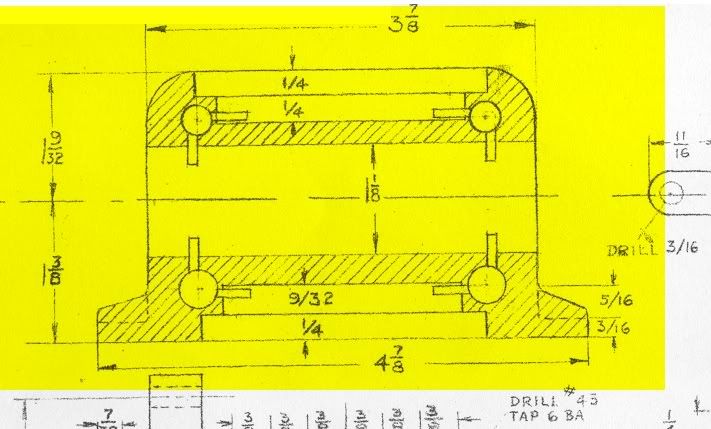
this is the Corliss cylinder that I will soon be starting on machining...

I need to machine and place porting slots as shown on the drawing...could I have your collective wisdom on the approach to this one Please.
All the best for now,
John.

http://i22.photobucket.com/albums/b329/corncrake/

seems to be the only way I can get this up on the web at the moment... the highlighted drawing is the cylinder in question...
 
Sorry, can't help, can't see the piccy, just a little red X.


Maybe our software guru, Tatoo Mike could assist.

John
 
Hello Bogstandard,
dont know what the problem is, if there is one, some times photobucket seems not to work so I gave the address for the whole site. lets you see some of the work I have done to date ;D
All the best for now,
John.
 
CORLISSmachiningcylinderNO2.jpg


Here is the drawing.

 
Hi John,
Without seeing any more drawing views of the component this one means nothing, it could be almost anything.

Sorry

 
Hello John,
at present my scanner and camera system is playing silly b......, so I am unable to show further on the drawing end...I can hopefully describe the job verbally...the cylinder is made from a block of gunmetal, oblong in shape, it has a
1 1/8'' hole bored for the piston as shown...steam chests (two stepped milled out section top and bottom of casting) are milled top and bottom of cylinder, depth as shown...inlet valves(Rotary type) by two and exhaust valves (at bottom) by two are bored across the narrow width of the cylinder...all of this I feel o/k with from the machining aspect...the drawing shows the steam ports as (SLOTS) leading from the valve chest and cylinder bore (two for each valve) the
edge of the slot has to be on the centre line of the valve...(inlet valves top...exhaust bottom) the valves are Rotary...Arnold Thorpe illustrated the porting
as akin to a solid cutter piercing through the hatched drawn part of the sketch into rotary valve from the steam chest and the cylinder...
My question, which I hope is a little clearer, what is the best method of accurately producing the slots...
All the best for now,
John.
 
I just hope that I have picked this up correctly.
The type of cutter you require is a woodruffe key cutter (http://www.icscuttingtools.com/catalog/page_283.pdf). It is very much like a small but robust slitting saw for putting the half moon slots into shafts for key fitting a component onto it.
My very very very rough sketch shows what one is like. I have made them by hand before now out of silver steel, filed up to shape with say four teeth and then hardened and tempered, then stoned up sharp with a wetstone. You would have to be careful when cutting because sometimes gunmetal can be a bit tough.
I have also shown how you would approach for cutting.

Hope this helps.


John

howtosketch.jpg
 
Hello John,
thinking about some sort of ''Saw'' cutting method earlier but did not think of ''Woodruff'' cutters, can not see any sketch or drawing you may have put up yet??? thank you again for any help also to ''Tattoomike68'' for his assistance...
this engine is proving to be a bit of a challenge both mentally and physically...
All the best for now,
John.
 
Here you are John,

sketch.jpg


Maybe you wouldn't be able to get a commercial one in unless you had the shaft ground down a lot, but they are very easy to make, especially if you have a rotary table, but can be filed and cut by hand if needs be.

John
 
that is spot on John, I will investigate if one is commercially suitable, if not, as you say I will just have to make one.
All the best for now,
John.
 
I have spun down older endmills on a tool grinder to make woodruff style cutters but it might be possible to spin an end mill in an electric drill against a regular pedastal grinder if your hand is really steady and neck it down in the middle for a ways . big end mills can some times be gotten at surpus stores or metal scrap yards
 
Hi folks,
I may just end up bodgeing something together, the port slots are two different widths...5/64'''' inlet and 3/32'' exhaust If I remember correctly and there are only 8 port slots to cut so the tools will not have to last a long time...these are a little Different from porting slots in Slide valves on Locos... ;D
All the best for now,
John.
 
John,
Easy enough, just make a rough tool at 3/32" then once those ports are done, grind it to 5/64" and finish off the ports.

John
 
HI Folks,,,it's been a while.....a lot of adjusting done on the shed to increase work space...new bench for big lathe ( 18'') more frontal room The ''Chester Conquest'' mill died !!! Burial was at local scrappie....Amadale provided me with a new one... longertable with plenty of engine power...very good machine......the Conquest worked on a 10v Score James Coombes...and a bed plate + machining the flanges of the Flywheel
At present the Corliss is a little over 1/2 way stage
A major problem occoured when I decided to bore out the cylinder ...all went to plan until the bar reached 1/2 waydown cylinder bore where it decided to let go walkabout then took a dive into the side of the bore ...!!! to cut a long story short (Problem caused by a HARD spot in mid bore Very prevalent in BRONZE) Firstly I made a classic mistake in set up......flat to flat works most times but will not be reliable where oil has been on the part or machine faces ( use Acetone to clean faces before assembly) after trying out various methods I ended up GRINDING it out ... I will now attempt to send some photos...
 
Hello Kellswater,
You are not the first person a mishap has happened to when boring out an engine cylinder Something like this happened to a local engineering concern in this area within the last few decades from memory about 1974? The late Glasgow sugar machinery manufacturers Smith Mirrlees, had received an order for a replacement cylinder for a big Corliss steam engine of their make, They sent this cylinder out to one of the local engineering firms to be bored out Half way up the bore on the finishing cut, the tool shattered, Naturally they were hesitant about trying to pick up the same cut again, So they past the cylinder over to another local firm who had a big home made honing machine This firm picked up the size using a Delapena hone, & finished the cylinder perfectly.
It is of interest to note the last big Corliss engine to be built in Glasgow was 1966 for a big sugar cane crusher
 
If I can enlarge on the cylinder ...after the dig in I attempted to get an idea of the depth of the damage ...the bore looked pretty good up to the hard spot ...1/2way ...so I set it up round the other way as true as possiuble the bore finished with a slight missmatch...very careful use of the boring straighjtened the bore some more....still a slight curve there ...now resorted to Hand Grinding out the hard spot Getting there !!! after a lot more work I had a cylinder ...although slightly o/s should work Next I fitted the front and rear covers ..My first use of the Rotary table for pitching holes...sort of went a little over the top on that.
. John.
 
Kellswaterri,

Who made the castings for your nice model, Is it a British set of castings or American, You certainly have yor project looking good.
 
Back
Top