connecting rods and bushings

Home Model Engine Machinist Forum

Help Support Home Model Engine Machinist Forum:

This site may earn a commission from merchant affiliate links, including eBay, Amazon, and others.
K

Kermit

Guest
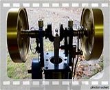
I think this is a unique type of rod bearing that would more suited to miniture models in that it allows the use of one single bolt to adjust bearing grip.

singlescrewrodbearing.gif


But how to provide with lubrication?


any ideas?

Kermit
 
You probably can't get a good look here...

But this engine has a zerk fitting. Since this is an "upside" down motor "splash" lubrication was insufficient. It does throw of a blob or two of grease, but that just teaches people not to be wearing a suit near me and my machines.

Zerk fitting for this one to...
 
so a standard zerk that one uses to inject grease?

If these bearings will work on grease and don't need oiling then that's my answer.

Thanks,
Kermit
 
Hi Kermit,

That's an interesting design! Have never seen it before. Have you considered using a grease cup? There are some on this page:

http://deboltmachine.com/_wsn/page6.html

You put some grease in the cap, then screw it onto the body. As you screw the cap down, it forces grease into the bearing. I used these on my Stickney hit/miss engine (from a DeBolt kit) and they worked splendidly. They are a bit messy to fill, however. :D

Paula

(PS... There doesn't seem to be a way to assemble that bearing, the way it's drawn up.)
 
Yes standard zerk for grease gun, with channels to allow grease get to where it needs to be. In my applications I am running for minutes to hours, so I can't testify to industrial use.
Depending on application it may work for you.
 
Hi Kermit
Iv been fitting taper adjusters on big ends on models for many years, with a split brass its the only way to get accurate bearing setup. It also allows any wear to be filed out of half the brass. Lubrication is by way of an oil cup.
I think you can just see the adjuster nut on the big end in this picture.

tractor5-1.jpg


Paula said:
(PS... There doesn't seem to be a way to assemble that bearing, the way it's drawn up.)

I see two half brasses, one with the slot on the flat away from the shaft. I'm not seeing any problems with it(the dwg). If I'm missing something I guess you're gonna have to spell it out for me.

Blind in one eye and can't see out of the other,
Kermit
 
Hi Kermit
I must agree with Paula on this,how do you get the flanged brass segment into the square hole?Is this a test or am I just dim?

puzzled regards Steve C.
 
Paula said:
(PS... There doesn't seem to be a way to assemble that bearing, the way it's drawn up.)

On staring at it with my med and caffotine soaked brain, I think I see it. It looks like the wedge piece on the right - the one held down by a bolt - can be removed leaving enough room to wiggle the rest out without resorting to large hammers, torches or bad language. Well, not a lot anyway.

I think.

Best regards,

Kludge
 
Could be that the flange is only on both sides at the left end, the right end would be held in place by the crank journal and wedge? If so, removing the wedge would allow it to come apart.

The individual who made the drawing has apparently left out some information. What exactly does the hidden line around the bore represent?

Kevin
 
I was thinking the dotted lines are the square body. A lip or overhang at the end opposite where the wedge goes in.
singlescrewrodbearing-2.gif

Wouldn't it have to have such a "stop". The wedge gets wider going up but smaller going down, so to stop the brasses from going the direction in which things get looser you put a ledge the prevents the brass bearing from going out that side.


? I think,
Kermit
 
Even if you remove the small wedge shaped piece with the bolt in,the two flanged brass segments are only free to slide either toward or away from each other along the length of the square hole.Assuming they are a good sliding fit in the hole they cannot be rotated in any direction to clear the flanges.Its even more fiendish than one of those wooden chinese puzzles.

regards Steve C.
 
Yes, I think the flange goes completely around; but only on the side the wedge goes into, the other side has no flange except at the extreme left. The halves could be dropped in then the wedge put in place, which should prevent the bearing halves from coming out.

The "dotted" lines forming the rectangle are indeed representing the rectangular through hole in the connecting rod; but the circular "dotted" lines are what I question.

Kevin
 
singlescrewrodbearing-2.gif


I think this is what it should look like.

Edit 1/3/09 Joeby is right the flange portion should be flipped from my drawings bottom aspect to a postion on top.

And perhaps it could work as drawn without a flange on either end? Just the pinch of the bottom bearing and the fit around shaft keeping it all inline.

The drawing has the left most and rightmost cross sections with different direction lines; indicating different pieces but I believe this is wrong and the two are one piece despite the direction of the lines. (It's from an old book)

 
Back
Top