rodw
Well-Known Member
- Joined
- Dec 2, 2012
- Messages
- 1,146
- Reaction score
- 340
I was watching Tom Liptons videos on how to cut a taper and saw how he used a sine bar to set the compound angle.
https://www.youtube.com/user/oxtoolco
I had a go at it but found it pretty hard to indicate the compound into position. after a bit more research, I saw another quick idea that I just had to try.
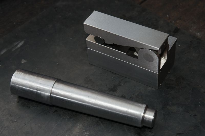
You see, I have this cute little 50mm sine bar with a magnetic base that I got from CTC tools while ago..
This is what I came up with.
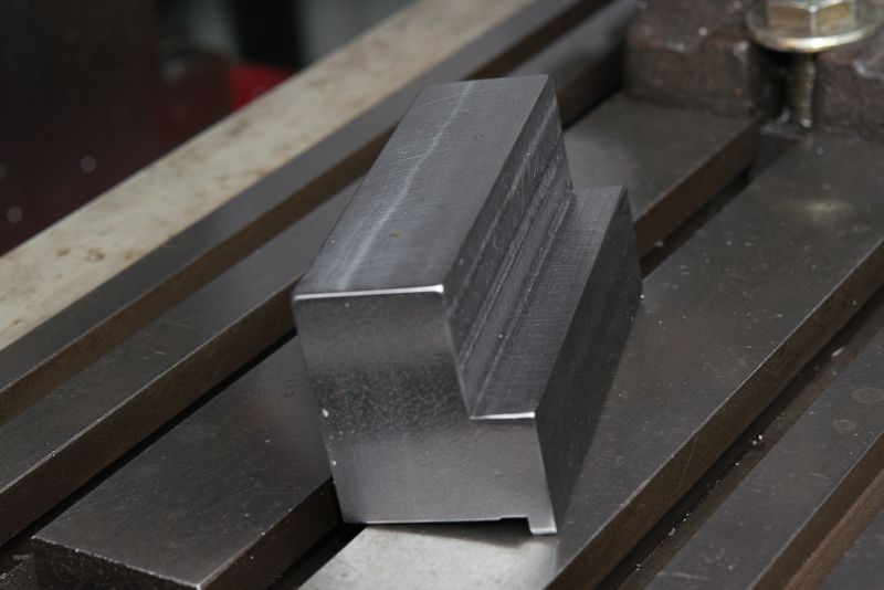
There is a nice recess for the sine bar to sit on and the magnet keeps it there!
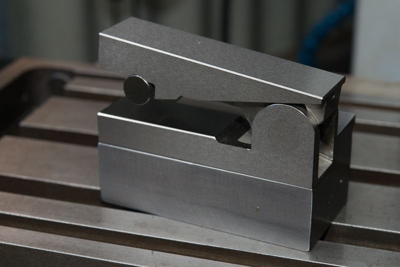
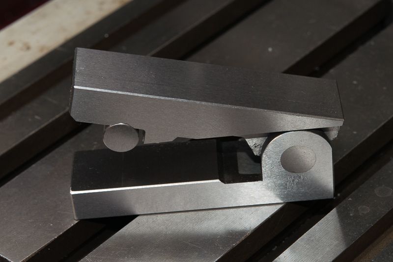
So now to put it on the compound
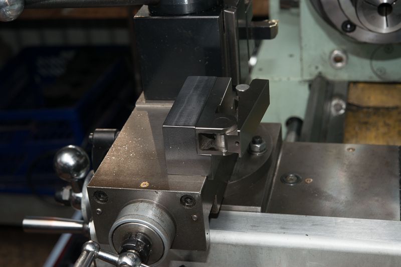
You can see the lip locates the bracket on the inner side of the compound
So now, set the angle you want with gauge blocks (I have set it parallel for the first test eg. No gauge blocks)
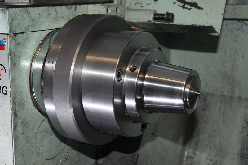
So now, just loosen off the compound, hold the bracket in position and sandwich the sine bar between the bracket and the tailstock.
The angle will be set perfect! well it was for me!
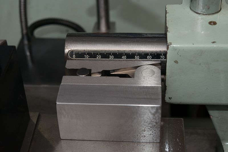
To test this, after I got it to kiss the tailstock, I set an indicator up along the compound edge the same way Tom did and the error was 0.00039" (0.01mm) over the length of the compound travel. I think that is within the accuracy of the compound and my el cheapo indicator so I have pronounced this as a winner!
That was enough for today, so my next project in my shed will be to try this out.
Some people may raise concerns about the tailstock being correctly aligned but those that have done this swore by it. I knew my tailstock was spot on from previous tests, but running an indicator mounted on the toolpost along it would confirm this.
https://www.youtube.com/user/oxtoolco
I had a go at it but found it pretty hard to indicate the compound into position. after a bit more research, I saw another quick idea that I just had to try.
You see, I have this cute little 50mm sine bar with a magnetic base that I got from CTC tools while ago..
This is what I came up with.
There is a nice recess for the sine bar to sit on and the magnet keeps it there!
So now to put it on the compound
You can see the lip locates the bracket on the inner side of the compound
So now, set the angle you want with gauge blocks (I have set it parallel for the first test eg. No gauge blocks)
So now, just loosen off the compound, hold the bracket in position and sandwich the sine bar between the bracket and the tailstock.
The angle will be set perfect! well it was for me!
To test this, after I got it to kiss the tailstock, I set an indicator up along the compound edge the same way Tom did and the error was 0.00039" (0.01mm) over the length of the compound travel. I think that is within the accuracy of the compound and my el cheapo indicator so I have pronounced this as a winner!
That was enough for today, so my next project in my shed will be to try this out.
Some people may raise concerns about the tailstock being correctly aligned but those that have done this swore by it. I knew my tailstock was spot on from previous tests, but running an indicator mounted on the toolpost along it would confirm this.