Communicating Compound Angles

Home Model Engine Machinist Forum

Help Support Home Model Engine Machinist Forum:

This site may earn a commission from merchant affiliate links, including eBay, Amazon, and others.

kcmillin

Project of the Month Winner!!!
Project of the Month Winner
Joined
Jan 19, 2010
Messages
1,193
Reaction score
41
In the process of Drafting plans for The TI4, I have encountered a stumbling block, or more of a stumbling head.

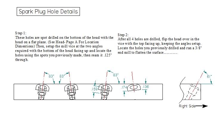
The spark plug holes are at a compound angle. The holes are located from the bottom of the head and reamed .125", then spot faced, countersunk, and threaded from the top. The problem is how do I determine the "Z" height of the end mill to get the correct depth for the spot face and all the other features. There is not a flat plane to dimension from.

When I made the head I determined the depth of cut by watching the end mill until the entire end mill was making a cut, or a circle was formed. Would it be to confusing just to write that down?

I included a drawing of the detail so far. It is not complete, hence this thread and the "..............." at the end of my description.
angledraft.jpg


Kel
 
That is always difficult to inspect and measure. When I was a drafter we dimensioned the critical point which would be the point at which the hole axis pierces the bottom plane of your head.The counter sink would be dimensioned from there along the hole axis, in true projection of course. How the guys in the shop ever set up and made the stuff I don't know, but they did make their own manufacturing prints, we made inspection prints.

I think though that your plan is fine. Describing it as you suggest should be understandable to most. An arrow pointing to the face you want the endmill to break just below might help. The .159 dimension concerns me as to whether this is the true distance or the projected distance in that view. A section view through the plug hole would make that clear.
 
In drafting parlance, there isn't a fixed dimension for spot facing depth, but is usually .03-.06". You can just notate SFACE or use the symbol |_|.

If the plans are intended for builders not familiar with the terminology then your explanation of the endmill making a full circle should suffice. The .174 and .136 dimensions are confusing in my view.
 
Hi Kel
When a job like this is being done to a critical dimension there is an item called a 'tooling ball'. This is a ball of a given diameter fixed to a stem. The tooling ball is mounted to the part to be machined and then through some compound angle calculating the tilt and rotation angles are specified. The machinist picks up the tooling ball (x,y and z) and sets his dimensions. He then proceeds to cut at the desired point and to the proper depth. For the shop machinist this is way too much information so I would do as kvom suggested. Put a note on the drawing stating 'x dia. cutter to full spot face'.
With the aid of a sine table you would set up the tilt to 29 deg. and then tilt the mill head to 7 deg.
For people like myself with a round column mill I would have to actually calculate the compound angle so that I could rotate the part on my sine table then tilt it to the proper angle. With AutoCad it's quite easy but doing the trig longhand is a pain.
gbritnell
 
Thanks guys, I think the 'Spot Face to .375" is a winner. I went back and reviewed the Drawing for the 'Tiny IC' and they have this same note.

Kel
 
I am wondering about the spot drilling from the bottom. The spot drilled hole will be at an angle, and I would be wary of the 1/8" drill veering off a bit. I think I'd just prick punch the location, and then start the holes by milling flats, then spot drill, then drill. That way the drill point isn't encountering a slanting surface.

Just my .02.
 
Good thinking kvom, I will add a note for this, plus it is the way I did it too.

Kel
 

Latest posts

Back
Top