CNC lathe course

Home Model Engine Machinist Forum

Help Support Home Model Engine Machinist Forum:

This site may earn a commission from merchant affiliate links, including eBay, Amazon, and others.

kvom

Well-Known Member
HMEM Supporting Member
Joined
Jun 4, 2008
Messages
3,285
Reaction score
630
I started a class on CNC lathe g-code programming last night. It's a once a week evening class that goes on for 3 hours or so. If anyone is interested I can "blog" the weekly progress.

In any case, the textbook used is Introduction to Computer Numerical Control by Valentino and Goldberg. I just found and ordered a used copy at www.alibris.com. The course can be passed without using the textbook as the school has online exercises and projects for each week, plus the lecture. We are then given a homework program to write for the next week's class.

The book comes with a couple of software programs that are crucial, and could be useful for anyone here. One is a g-code editor that does syntax coloring and line numbering. The other is a simulator named Virtual CNC. Using this program, we defined a "job" that specifies the machine, stock to be turned, tools to be used, and the g-code program to emulate. You can then run the job and view the completed part in either 3D or cross section. The program is a "demo" version for students and limited to 150 line programs.

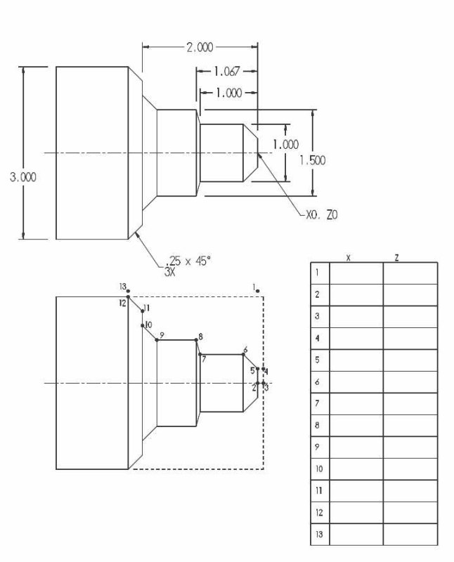
The first exercise was a simple program that just does facing and an external contour. For next week's class I need to program a part with external turning and internal drilling and boring.
 
kvom said:
.... If anyone is interested I can "blog" the weekly progress.

...

Blog it and they will read. or at least I will!

Eric
 
Software comes with the book. I ordered a used copy of the book online and won't have it for another week or so.

Here is the print for the first exercise:

large.jpg


The first thing to learn is that the Z axis is along the spindle and the X axis is the crossfeed. I had expected it to be X and Y, but apparently the standard is that Z is always along the spindle. The X+ direction is "up" towards the back of the lathe (where the tool is on the bigger machines). Z+ is to the right, so that most Z coordinates are negative towards the headstock. The other important concept is that X coordinates are given as diameter. With this info I was told to fill in the coordinates of the numbered points, with point 2 being 0,0. Once the points are identified, the program will use the G01 code to move the tool from one to the other along the profile.

The dotted line is the stock, so you start by moving the tool to point 1, which is .100" outside the stock via G00. The the cutter moves to point 2, which faces the stock. You actually have to move a bit further in the -X direction to account for the nose radius of the tool. The use G00 to move successively to points 3, 4, and 5 to start the profile. Then a succession of G01 codes cuts the profile moving ending at point 12. Then G00 to 13 to clear the stock and then another code to home the tool back to the holder.

In reality you couldn't cut the profile with single cuts, so we will learn how to program repeated successive cuts later on.
 
At the second class we spent quite some time discussing carbide inserts: their sizes, shapes, nomenclature, and holders. I'm not sure how much is critical to a home CNC. Some of the more interesting points:

1) It's critical that an insert be clamped snugly in its holder/pocket. Any movement of the insert will cause it to break.

3) There are special inserts for aluminum that have a more agressive chip breaker in order to avoid long stringers.

4) The "trigon" shape is economical in that it has 6 cutting edges, as opposed to the diamond shape which has 4.

5) In order to promote maximum use, inserts with 0 relief are popular in that they can be turned over. To provde the needed relief the holder itself is angled.

As for g-code programming, we discussed the need for nose radius compensation when turning tapers or arcs. The principle is this: the insert will have a rounded nose of a given radius, but the lathe considers the cutting point to be the intersection of horizontal and vertical lines tangent to the nose. So lacking compensation, the part would have incorrect dimensions.

The solution is to turn on compensation via the G41 or G42. The code should be placed on a move (G00 or G01) command that precedes the first cut to be compensated. Then the cutting point is held to be tangent to the nose regardless of the angle being cut.

For the lathe to know how to compensate, the tool's nose radius and nose vector (orientation vs the spindle) must be entered into the tool table.

Compensation should be turned off at the start of the program via G40, as well as before every tool change.

Although we didn't get to discuss it in class, the homework assignment for next week is to write a program that includes the G94 (facing cycle) command as well as incremental moves using the U and W words.
 
Back
Top