sergeantmasoner
Member
- Joined
- Feb 7, 2015
- Messages
- 7
- Reaction score
- 5
Hmmmm....
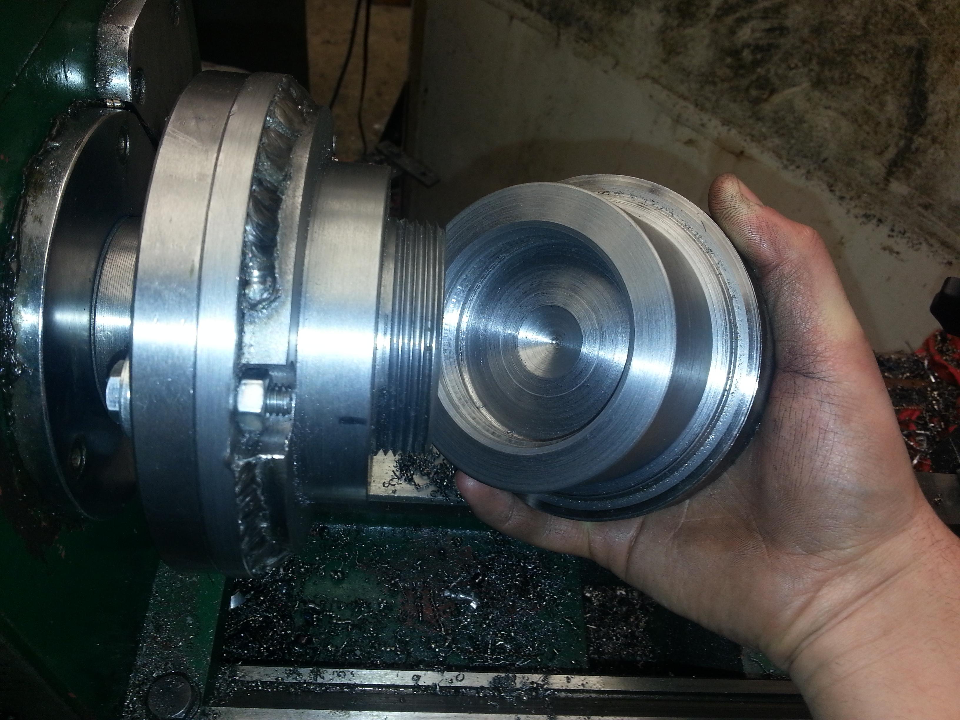
I wanted to be able to swap my small 5" 4 jaw, or other chucks from my HF 93212 7x10" mini to my C.Atlas 101.xx 12x33" and back. The HF has a 66mm three hole mounting bolt pattern with a 55mm register, and the C.Atlas has a 1 1/2"-8 spindle nose. Rather than having to bolt and unbolt the chuck from an adapter on the C.Atlas, I figure it would be easier to bolt an adapter to the HF and unscrew the chuck FROM the adapter to go directly on the C.Atlas and back.
Step I - Need a way to test the fit of the adapter. Produce a test mount with the dimensions of the HF mounting nose. This mount screws on to the C.Atlas spindle directly and has a register recess of 55mm diameter. You can see the progress in the picture below. This started life as a 1"x5" aluminum block and progressed through a screwed up attempt to make a faceplate. Oh well, I salvaged the material for this! Next, I'll have to produce a bolt patter of three M6 mounting holes at 66mm diameter.
This mount will also serve as an adapter for the actual adapter blank so that I can turn it on the C.Atlas.

Step II - Produce the adapter which will allow the mounting of a chuck with 1 1/2"-8 threads to the HF. The adapter will bolt directly to the HF and will have the necessary 1 1/2"-8 mount nose.
I wanted to be able to swap my small 5" 4 jaw, or other chucks from my HF 93212 7x10" mini to my C.Atlas 101.xx 12x33" and back. The HF has a 66mm three hole mounting bolt pattern with a 55mm register, and the C.Atlas has a 1 1/2"-8 spindle nose. Rather than having to bolt and unbolt the chuck from an adapter on the C.Atlas, I figure it would be easier to bolt an adapter to the HF and unscrew the chuck FROM the adapter to go directly on the C.Atlas and back.
Step I - Need a way to test the fit of the adapter. Produce a test mount with the dimensions of the HF mounting nose. This mount screws on to the C.Atlas spindle directly and has a register recess of 55mm diameter. You can see the progress in the picture below. This started life as a 1"x5" aluminum block and progressed through a screwed up attempt to make a faceplate. Oh well, I salvaged the material for this! Next, I'll have to produce a bolt patter of three M6 mounting holes at 66mm diameter.
This mount will also serve as an adapter for the actual adapter blank so that I can turn it on the C.Atlas.
Step II - Produce the adapter which will allow the mounting of a chuck with 1 1/2"-8 threads to the HF. The adapter will bolt directly to the HF and will have the necessary 1 1/2"-8 mount nose.