Ceramic Gas burners on Locos

Home Model Engine Machinist Forum

Help Support Home Model Engine Machinist Forum:

This site may earn a commission from merchant affiliate links, including eBay, Amazon, and others.
Cris

On the subject of blowers I can run without one up to about 5psi of gas, once the gas feed pressure is increased above this the smell of unburnt gas can be obvious. Adding the blower aids the combustion and higher gas pressures can be used. When I'm running at 30 psi of gas pressure I must get the loco blower on before the regulator is closed otherwise there will pop as the burner goes out. Normal running sequence for coming to a stop is blower on, regulator shut off. If stopping for an extended period I turn the gas down to 5psi and shut the blower off.

On a restart, blower on, gas to 20psi, recover pressure, normal starting procedure with drain cocks etc. Once I'm running blower off, and gas to 30psi. As I've said before it will loose boiler pressure if running at only 20psi gas pressure.

By being patient the loco can be started without an external blower; 5psi of gas to get up to 12-15 psi boiler pressure open the loco blower gently and then gas pressure can be increased as boiler pressure increases and the blower goes harder.

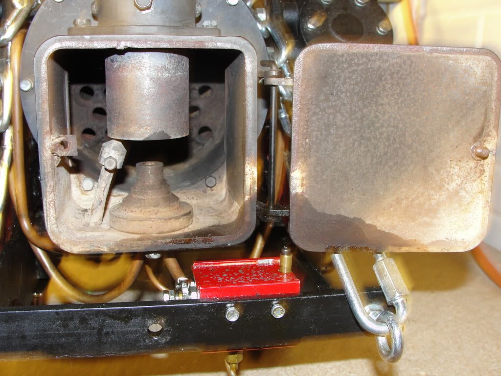
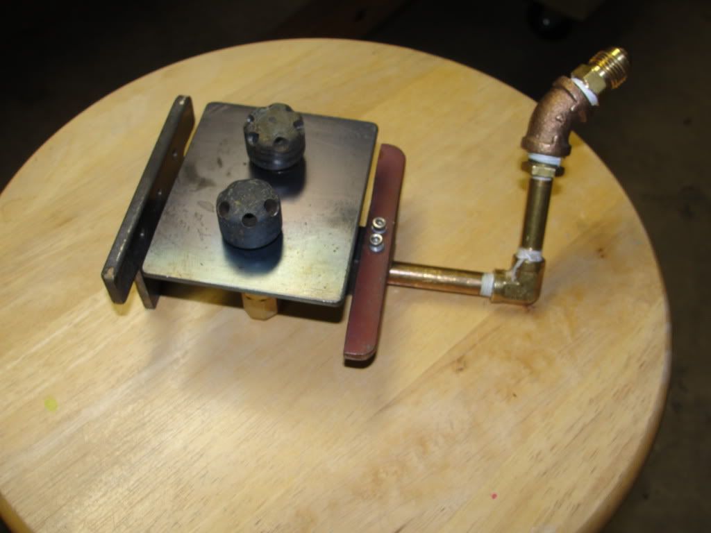
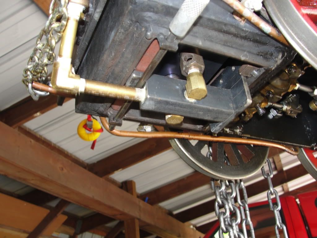
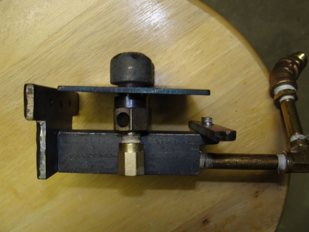
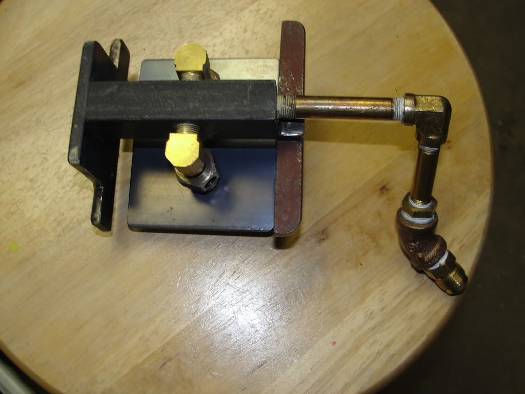
By the way, adding the secondary air tubes to the burner markedly improved it and flame outs now rarely occur if I follow the procedure above. The original ceramic burner was hard to keep alight when pushing a lot of gas through it.

With your calculation showing a burn of 73g/hr and the Little LEC results indicating say a typical efficiency of 0.4% am I correct in saying that would indicate the loco would really require 18.250Kg of gas to run for an hour? Which I know would be excessive I've just about managed two weekends with a 3Kg bottle when I went for a refill it had 750gm remaining. I now have a cycle trip meter on my new driving trolley, last weekend I did a total of 3.6km, with 53min of run time (in motion) and an average speed 4.0 km/hr. There was also a considerable amount of standing around time with the burner going.

Like you I need some scales so In can properly measure bottle use.

You may find this useful http://webspace.webring.com/people/ib/budb3/parts/ste.html there are many web pages with this formula, this is the first one I found. I was reading the same in a 1929 copy of Greenley's book just the other week.

Pete
 
doubletop said:
...

With your calculation showing a burn of 73g/hr and the Little LEC results indicating say a typical efficiency of 0.4% am I correct in saying that would indicate the loco would really require 18.250Kg of gas to run for an hour? Which I know would be excessive

...
Pete

Hi Pete,

No, I have calculated steam use at full throttle for a particular engine speed, assuming all heat from the burner is converted to evaporating water at 155°C/80psi.

This has nothing to do with efficiency, which is the conversion of the total heat of combustion into actual mechanical work, i.e. "what is the force integrated through time needed to move the train as it did over a trajectory". The main contributors there are rolling resistance and pulling weight up gradients. This is also why the Little LEC results are not so transparent - they have calculated the necessary constants for driving trolley resistance and the track profile, probably from a run with a dynamometer car at some point (or anyone's best guess, which is less work, but also gives less accurate results), and use these numbers for arriving at the efficiency. The numbers are not given in the article, which says "contact the organisers if you want to see the details".

Whether the loco can actually attain this speed the calculation is based on and stay at it for extended periods of time is a different matter entirely - chances are it won't, and the difference is largely due to heat loss.

The upper theoretical limit for the efficiency of any heat engine is given by input and exhaust steam temperature. Our small engines operate at reduced steam pressure from their large cousins (typically 8, 10 or 12 atmospheres) . In addition, heat losses are far more important in our small locos. In any steam loco, part of the potential mechanical work is blown out the stack due to the lack of a condenser. The ideal scenario would be something akin to a high speed Newcomen engine, where high pressure steam is injected into a cylinder and then perhaps cascading to a few compound engines, in the last of which the steam is condensed so the cylinder reaches vacuum prior to the next injection of steam.
In practice, this has never been feasible for a locomotive.

There have been some experimental high pressure engines working at the optimum pressure for steam of about 60 atmospheres (the benefits of any additional rise in pressure are marginal compared to the draconic design requirements) , but they have never been a great succes, due to their propensity to kill their operators at some point. High pressure technology was not quite what it is today in the first part of last century.

The 73g/h I calculated should be pretty close to the actual figure for normal running, that is, with the throttle partially shut or the cutoff reduced when the train is moving, and with periods of standing still. These times when less steam is used compensate for the heat loss, comparing for example my 88 g/h on what could be an emulation of a "typical run" compared to 73 g/h theoretically. My gut feeling is that a large part of the heat loss happens in the steam pipes to the cylinders and cylinders themselves, as well as from boiler appendages, and perhaps a minor part radiating from the boiler itself. Another large part of the heat loss is the hot flue gases blown out the stack.

Have a look at this test:
http://www.whitetrout.net/Chuck/844/Tests/Lagging/Index.htm

The heat loss from the boiler (which has a much larger surface area than our small boilers obviously) is 13,9 MJ in one hour, corresponding to a continuous heat output of 3,8 kW.
I'll look into doing a similar experiment at some point - it could be improved upon to provide more data besides the sense and nonsense of boiler insulation.

As an aside, since the heat of combustion of 73g of propane is only 3,4 MJ, our little burner couldn't even come close to keeping this large boiler up to temperature. With 73g of propane/h a burner is equivalent to 0,9 kW (that means, it puts out 0,93 kJ per second for 3600 seconds to arrive at 3,4 MJ in an hour).

Now, if on Sunday, I find results wildly different from my guess for the gas usage, I won't hesitate to let you know :)

Cris

 
Cris

Thanks again for a comprehensive explanation. While you were doing that I took a look at the Little LEC results published in ME 4389 to see if I could make any sense of them. With the help of parameters from conversion websites I was able to derive the same efficiency results. See the attached it shows the calculations for each of the values.

I then looked at the results from the 2008 Little LEC available here http://www.stationroadsteam.com/LittleLEC/2008/index.htm they don't have all the parameters such as run time but realized that time wasn't required to derive the efficiency as it cancels out in the power out/power in calculation.

The track constant used by Little LEC remained a mystery until I found http://www.littlelec.co.uk/home/

In our case weighing the gas bottle before and after should allow the input BTU's to be established by way of a comparison.

Pete


Attached

View attachment Little LEC.pdf
 
This may be a bit off topic but to support gas burners you need to be able to drag the gas bottle around with you. I'd been using a riding trolley, fitted out for gas, on loan from a club member. I needed to make my own and had some basic parameters I wanted to achieve.

be lighter than the 39Kg of the loan trolley.
be able to carry me (100Kg)
be able to carry primus gas bottle
have gas controls and gauges.

This is what it turned out to be
6gezimv4g5jgtqa4g.jpg


ssarccmmbv6hgzk4g.jpg


Its made out of aluminium 20mm x 40mm x 3mm box section as we have a supplier 10 mins from the house. Once I'd machined it all up they welded it for me.

g5xnm0f0u589wb34g.jpg


I got the bogies from One Inch Railroad in the US http://www.oneinchrr.com/index.htm. They'll supply with 119mm back to back spacing for SMEE standard tracks rather than the 4.75" used in the US.

cdxgfox717v3o4o4g.jpg


I fitted my own design brakes as the One Inch Railroad brake kits only fit 4.75" spacing

2ol8k49javqbf2m4g.jpg


Gas controls

Gas cutoff - red lever.
Regulator pressure - left gauge
Pilot control - small knob
Main control - large knob
Jet Pressure - right gauge

2ol8k49javqbf2m4g.jpg


I got a bit carried away with 'features'. Once I had the loco running well my next problem was water supply so I fitted a water tank (lunch box) and pump run from 12V SLA battery. The red button on the control panel operates the pump.

bg1bmlq2ylzcxwi4g.jpg


The orange unit next to the battery is the gas regulator. The gas pressure being read on the left hand gauge

You'll also see from the photo a cycle computer has been installed and that proved to be very successful. However, it only measured in units of 100mtrs so is being replaced with a home made computer and display using a PIC micro. That measures distance in units of 1 metre. It's up and running and just needs to be installed.

I hope that's helpful

Pete
 
Dear forum,

I have, over the past few weeks, tweaked my little homebrewed ceramic burner according to Pete's recipe a bit more, and I have arrived at this result:

[ame]http://www.youtube.com/watch?v=EcjDqTTnx78[/ame]

Crucial in the success were the use of propane instead of butane, allowing to push a lot more gas through the burner, and careful tweaking of the mixture by a moveable and fixable shroud over the (too many) air holes in the mixing tube.

All is peachy now - I love that little loco! Scale speed is on average 55-60 mph in the video. On the real thing, that would be beyond scary.

Some thermal efficiency testing will be done later, until now, with several test runs of about 2.5 hours total, I have used around 300g of propane.

With best regards,

Cris
 
tups said:
All is peachy now - I love that little loco! Scale speed is on average 55-60 mph in the video. On the real thing, that would be beyond scary.

Very nice little engine - goes like a Rocket? Just one thing; if the original had springs they would have been much stiffer than yours. I think the roll induced by the angled cylinders is far too much.
 
Cris

I be you are pleased with that? It was going really well and I noticed the safety blowing off while under way, so plenty of steam being created. That tall smoke stack wiggling about looks a bit scary but no doubt it wasn't as bad as the video would suggest.

I'm keen to see your calculations so I can judge how inefficient mine is and maybe do something about it. As you know I tried the 450g Coleman cylinders but didn't think they held enough gas so moved up to the 2Kg Primus cylinders. You may prove me wrong and get me to move back.

Congratulations and well done.

Pete

 
Dear all,

The picture server I used for the pictures in this thread has gone belly-up in the mean time. I tried editing my posts, but that does not appear to be possible - hence here a repost of the pictures that used to go in my messages earlier in this thread.

propane data chart
propaneflow.jpg


loco data
locodata.jpg


and some burner pictures


IMG_3040-1.jpg


IMG_1313.jpg

IMG_1314.jpg

IMG_1315.jpg

IMG_1316.jpg

IMG_1318.jpg


As for Rocket, I still have not gotten around to efficiency tests, because I'm having too much fun running it!
 
Hello everyone,

Thanks again for your posts. I am learning a great deal about ceramic burners, and I greatly appreciate your comments and photos.

I wanted to show a picture of my 1/8 scale locomotive, a model of the 1830s vintage Invicta, one of the first locomotives made by the Stephenson Company in the UK. Eventually I plan to install some type of ceramic propane burner.

6bc08a2b.jpg
[/IMG]

The model was made by an excellent machinist by the name of Jim Zeeler, who lives near Columbus Ohio. I found it for sale on www.discoverlivesteam.com. His shop is remarkable. He had twenty of the same model engines on display, awaiting sale.:D

The engine is designed to run on coal. I'm experimenting to make it run on propane. Before I discovered this forum (and the Unofficial Mamod and Steam Forum), I knew nothing of ceramic burners. My experiments have been with modified "Marty burners" which are fashioned from a coffee urn. Below is a photo of the Invicta lifted from my work bench with a chainhoist.

da0f4553.jpg
[/IMG]

The next photo is a closeup through the bottom of the empty firebox.

af968409.jpg
[/IMG]

The next photo is of the burner with fittings from two coffee urns. It has a flame deflector, which I installed after learning from this forum.

1246f048.jpg
[/IMG]

The last photo is a closeup of the burner fitted into the firebox.

85a815ef.jpg
[/IMG]

Please feel free to let me know what you think.

Eventually, I'll enter the world of ceramic burners with this engine. I haven't met anyone who has done this in a 1/8 scale steam locomotive (at least not in my little world of Michigan, USA). You guys could teach us a lesson.

In the meantime, I'm having fun running this little engine. Here is a brief YouTube video.

[ame="http://www.youtube.com/watch?v=MQ1ZqE9IxRE"]http://www.youtube.com/watch?v=MQ1ZqE9IxRE[/ame]

Cheers
 
Chris

Apologies for not replying. It appears that the new site doesn't notify contributors to posts from the old site.

That's a great loco and I somehow suspect that your burner is the best option for a loco of that size. The trouble with ceramic burners is they fill the firebox space and getting secondary air into the flame area becomes a problem. I sort of dealt with it by putting tubes through the burner. But if you take that to its extreme you end up with a burner like yours.

At some point I'm going to try a "Marty Burner" which are similar to yours.

http://www.discoverlivesteam.com/magazine/186/index.htm

Pete
 
Hello

In my last post, I showed a propane flamethrower-type burner for my 1/8 scale steam locomotive, the Invicta. It had a baffle plate.

My goal was to open up the bottom of the firebox as much as possible, in order to let plenty of air flow in. This was a mistake.
The flames blew out whenever I opened up the throttle. Too much suction from the fire tubes. I had the same problem after removing the baffle plate.


1246f048.jpg
 
I prematurely hit "submit."

Sorry.

The locomotive was originally designed to run on coal. I guess this is why so much draft was needed through the firebox. I fixed the problem by enlarging the hole size on the exhaust port directly beneath the smokestack. Here is a picture of the smokebox, with its door open. You can see the blower on the left side.

2cbde4a1.jpg


I also set a steel plate directly beneath the flamethrower jets. I got this idea from reading the posts on this forum and the Mamod steam engine forum.

7b639408.jpg


The plate is smaller than the firebox, making a 3/4 inch air gap between the plate and the firebox walls . When the throttle opens up, suction from the firetubes pulls air through this gap, keeping the high velocity away from the flamethrower outlets. Here is a view of the underside of the locomotive, with the flamethrower installed.

f391dd35.jpg


This weekend I drove the hell out of this locomotive and the flamethrower never blew out (until I ran out of propane).

Here is a side view of the flamethrower.

19881321.jpg


And here is a view of the flamethrower upside down.

03006467.jpg


One last view of the flamethrower, also showing my latest creation: the beginnings of a cow-catcher, made from a chunk of steel cut out of a piece of full-scale railroad.

45142b4c.jpg


I'm addicted now.

What does this have to do with ceramic burners? I'm still interested in making one. My sense is it'll perform better than the flamethrower because it uniformly produces heat across a large, flat area.....much like a bed of coals.

Cheers
 
Looks like great progress, Chris.
If you are happy with locomotive performance as it is, I would keep what you have, and forget about a ceramic burner.

I forcibly redesigned my ceramic burner after the mixing tube started to look like Swiss cheese from experimenting with the jet location and the location of airholes. I designed a new mixing tube with 4 elongated (about 10mm) 5mm wide slots milled into it, and the jet just shy of the rearmost edge of the hole. That worked very well last weekend, running the loco all day long, and going through 2.5 lbs of propane, without running too rich, as had been a problem earlier.

However, from my experience, having the ceramic glowing like a bed of coal is an illusion. It will do that, on low burner settings. If you crank up the gas to the volume needed to sustain high speed running, the gas flow and secondary air from the exhaust suction cool the ceramic so much it will simply be dark with blue flames - but it will put out the maximum amount of heat.

Cris
 
I'm with Cris on this 7.25/7.5" guage is a big loco for a ceramic burner. If you aren't getting the heat you need with the 2 "flamethrowers" why not make an array of 4. If that's too much adjust the jets or gas pressure to suit.

If I was to make a burner for my 5" gauge Simplex on gas I be trying those Marty Burners.

No doubt Cris could quickly do the maths on how much heat would be required to be generated for such big locos but I believe with the pressure and jet sizes I'm using for the Rob Roy I doing 11KW/hr and the Northumbrian about 8Kw/Hr and I don't think its enough. I somehow doubt a ceramic burner would do the job for the larger scales, although Cris has been quite successful with his Rocket.

Pete
 
Cris

Your burner looks perfect but what you describe is exactly the scenario I had, which then proved to be disappointing on the track. In fact I was out running this weekend and my experiences contribute to my growing understanding and help me answer your question.

Pressure building seeming a little slow would indicate not enough heat to maintain the steam pressure. The problem is you can't just push in more gas without means of drawing the air through the boiler. So my suggestions, in some sort of order.

Your loco looks pretty new. It needs to be loose to enable this to work. I was told to run mine on air for a long time to run it in. I ran it for 6 hours plus keeping it well lubricated all the time. Varying speed, reversing etc. It should only need 5-10psi of air pressure to do this, so its not a case of thrashing it.

Put in the stainless baffle, unless you do, once you get enough heat it will ruin that beautiful paint job around the smoke box.

If you haven't already got it rig up some means of including a pressure gauge in the gas feed after the regulator, before the jet, so you can see the jet pressure. That way you'll get to learn what works and what doesn't. A 0-60psi gauge will do. I use guages from Norgren http://www.norgren.com8BSP 40mm gauge. They are off the shelf in NZ so wherever you are I'm sure you'll be able to get one.

Use propane if you can otherwise you'll need more butane to make it work and you may not be able to get enough gas through your burner to make enough heat.

Use an electric fan on the flue to start with, you'll see I use an old fan from a computer.

Put in the fan, start the burner on a low pressure (2-3psi) to warm things up a bit. leave the blower, regulator and drain cocks all open to let heat through the system.

After 2-3 mins shut the blower and regulator and open the gas pressure up to 5-10psi and wait for the loco pressure gauge to rise to about 20-30psi. Crack the loco blower just enough so you can hear it in the flue. Leave it like that for a couple of mins. Boiler pressure should keep rising.

Remove the electric fan. Increase gas pressure to 15-20psi. Boiler pressure should come up pretty quickly and the safety valve blow off.

With gas pressure at about 20Ppsi and running on the rollers without a load, and blower shut off it should be possible to run the loco and maintain boiler pressure to the extent that the safety blows off while you are running. If it doesn't try more gas pressure, but make sure its burning all the gas. You'll smell it if it isn't.

If you shut down the regulator remember to open the blower and reduce gas pressure to about 3-5psi otherwise the burner will go out and be at risk of flash back when you try to relight.

The gas pressures quoted are what works for me. The jet size plays a big part on the gas pressure required. I have a #15 jet. If you use a smaller jet you'll need more pressure and vice versa as the gas has still got to get to the burner at the right rate.

I also had an issue with pressure loss when running. I ran it on air, upside down, and used soapy water to trace leaks in glands unions etc. Try that

My experience this weekend re-enforced all this. My gas bottle was getting empty, which means the pressure dropped off and as I can only get propane/butane mix (LPG) the propane tends to go first leaving the less efficient butane until last. Once the bottle pressure got below 25psi and I couldn't maintain 30psi gas pressure, when running, the loco just packed up and I was back to where I was a few months ago. Its a fine line between right and hopeless.

Please re-post your question to me on the main thread and I'll copy my reply over as well for all to see.

Good luck

Pete

(just had another look at you pictures, beautiful!!!
Can you give us a little schematic of the gas buggy/car? It is interesting but it will not blow up enough to read the gauges. It looks like you need one gauge for the tank, one for the post regulator and one on the jet?
 
Rick

I was going to have a gas bottle pressure gauge but it wasn't necessary

g5xnm0f0u589wb34g.jpg


The gas bottle connects directly to the regulator and the regulated pressure fed to the control panel

j7wf1qtpw5vnv244g.jpg


From the regulator the feed goes to the red 'T' handle which enables the gas supply to be cut off quickly.

Then to the left hand gauge (0-60psi) to indicate regulated pressure. This should remain constant when the pressure drops the bottle is getting empty. I set the regulator at about 40psi.

Then two valves to control the jet pressure. These are in parallel the smaller one to just give a low level 'pilot' flame with the jet pressure gauge reading something below 5psi. This allows the main control to be shut off without the flame going out. The larger knob controls the main jet pressure. There aren't two jets just two means of controlling the gas flow.

The second gauge is the jet pressure gauge, between the two control valves and the jet. This is 0-25psi gauge. of course the jet pressure is dependent on the size of jet you are using and the amount of gas you can get your burner to burn. I run a #15 jet at about 15-20psi. As the boiler is coming up to steam I slowly increment the jet pressure in 5psi steps. Once steam pressure is about 30psi I use the loco steam blower and remove the electric fan and the jet pressure at 15-20 psi. Boiler pressure comes up very quickly from this point.

The push button is for a water pump for the reserve tank I have on the wagon.

Hope that helps

Pete
 
Photos reinstated following the Photobucket problem

More to do

Pete
 
Has anybody tried building a set of Walchaert gears to control the steam more efficiently? I built such an engine several years ago but have not applied it to anything as yet.

Tom
 
Has anybody tried building a set of Walchaert gears to control the steam more efficiently? I built such an engine several years ago but have not applied it to anything as yet.

Tom

Tom

Posted on the wrong thread???

Pete
 
It’s been a long time since I posted on this thread as I've moved to loco's that are coal fired However, I still get the occasional query and it seems that this thread has become bit of a reference so I'll post this here.

I got my jets from a model engineering supplier but recently I've purchased a 3D printer and sought a supply of extruder nozzles so turned to Aliexpress. They arrived today and my immediate thought was "these are gas jets". I hadn't noticed the similarity before. It’s understandable really, hobby 3D printing gained a foothold with RepRap and where else would they get nozzles?

Barely US$8 for 22 "jets" with shipping.

US $2.58 11% OFF|22 Pcs Nozzle MK8 Extruder Head 3D Printer for creality CR 10 CR10 Machine Heads 1.75mm|3D Printer Parts & Accessories| - AliExpress

22-Pcs-Nozzle-MK8-Extruder-Head-3D-Printer-for-creality-CR-10-CR10-Machine-Heads-1.jpg_Q90[1].jpg


Pete
 

Latest posts

Back
Top