Cast iron crankshaft?

Home Model Engine Machinist Forum

Help Support Home Model Engine Machinist Forum:

This site may earn a commission from merchant affiliate links, including eBay, Amazon, and others.

grizelli

Active Member
Joined
Dec 24, 2013
Messages
30
Reaction score
7
Hi all. I have been working on a new engine and am having trouble getting a strong and true crankshaft - the engine is a horizontally opposed 2 stroke, with two 'clapping hands' pistons per cylinder, which makes it difficult to make a non-wobbly fabricated crank. The bores are 30mm with each piston having a 30mm stroke, so its not a small engine

I am wondering if anyone has had experience of cast iron for building up the crank? I can't cast one, but I have a supply of grey (meehanite) cast bar which I could machine. Is it going to be man enough for the job? Don't want to go to all the trouble of making it only to have it fly to pieces

Thanks for any advice

Martin
 
Hi Martin

2 stroke signals high rpm to me so I am sure something better is needed for the cranshaft, I should say though others with more experience my provide a better answer.

Emgee
 
i just finished a dual opposed engine and I machined the crank from 1144 stress-proof steel. It is very stable and never moved when i machined it. ---Brian
 
I would not use grey cast iron, better with SG Iron, I have done cast cranks from that but it won't be easy to join if making a built up crank.

I have also done a 25mm bore x 25mm stroke opposed twin and cut from a solid piece of round EN8
 
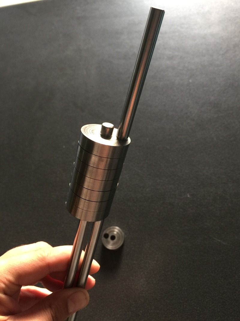
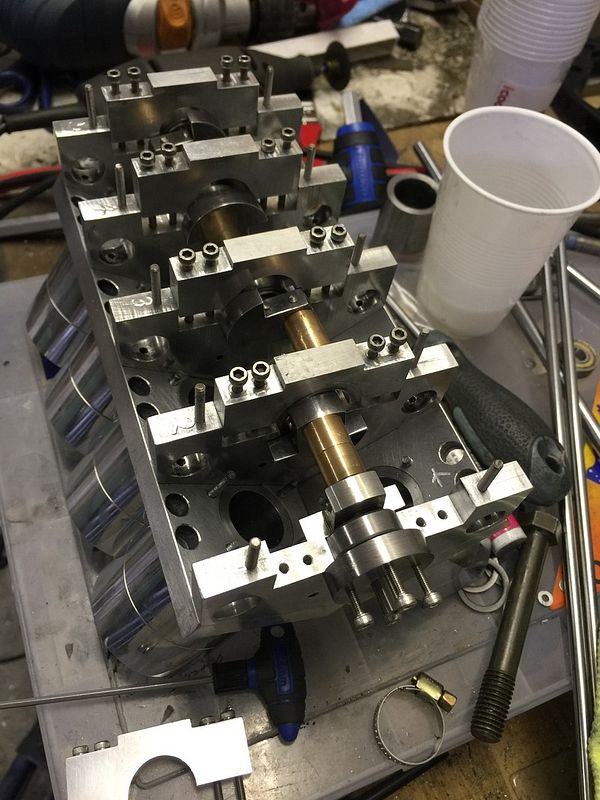
Thanks chaps. I suspect that I knew deep down that the CI was not really going to work, I guess it could if it was massive enough but I don't have space in the crankcase for that. Looks like machining it from a solid bar is the best option, fabricating is not really rigid enough and alignment of the pieces is hard to do, the last one I made it took more time and material to make the assembly jig than to make the crank. This is a picture of the trial assembly, this was the point where I realised the crank wasn't straight enough. Ah well.

17040003.jpg
 
Hi Niels,

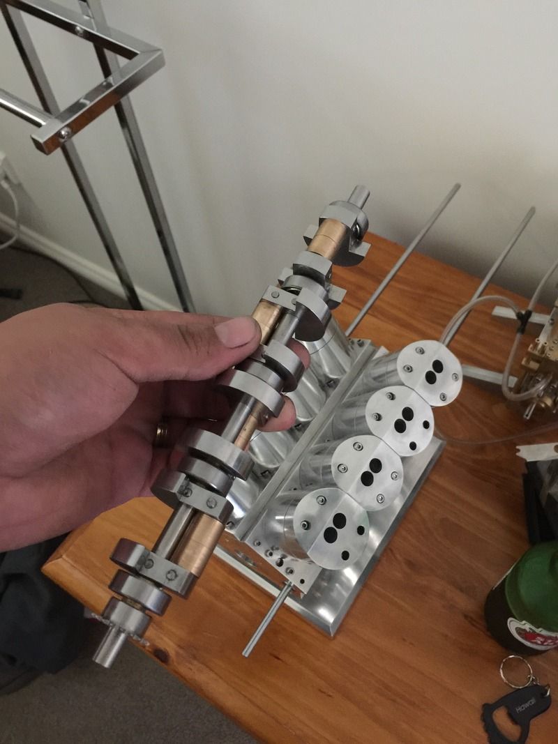
Unfortunately the design of the engine makes the crankshaft a little difficult. There are two cylinders with two pistons in each, firing in the middle of the cylinder. In each cylinder, one piston operates the exhaust ports and the other the inlets, with a small supercharger to provide some positive pressure to the inlet side. I have also offset the inlet crankpins by 15 degrees to keep the inlet ports open for a while when the exhaust ports are closed to allow for a bit of pressure buildup in the cylinder. It seems to work, but it makes it hard to fabricate and align the crankpins. The engine is based on the UK Commer TS3 engine, very popular in the 1960s
 
Gday grizelli

I'm just curious with how you made your first crankshaft and how you had alignment issues? The method I followed is very simple and involves turning a piece of steel to required length and diameter, then mounting each crank disk onto it and loctiting in place. Then drilling the disks and pinning them for further strength. Then on the mill each section is milled out or cut out where needed.
How have you done yours and what is the strength issues you're having?
 
Hi Parksy,

I'm new to this model engine game, so learning as I go. The crank has four separate throws with webs in between each one, and I solved the alignment problem by making a flat on each of the webs and using that as the reference point for drilling and assembly. The problem I have is more one of straightness than alignment - the crankpins are pressed in, then clamped with a screw and pinned to keep them from coming loose, which seems to work ok, but the shaft is quite 'rubbery' and I can't get it to run true, and because its quite long (around 120mm) even a small runout adds up to significant wonkiness at the ends. Even with this, the engine would probably run ok, but I'm using toothed belts to drive the oil pump and the supercharger and the runout will cause issues there I think.

I'm going to try machining between centres from a solid steel bar and see if that gives it less rubberyness - even if it does end up with some runout, I may be able to straighten it with a press.

I still like the idea of a fabricated crank rather than throwing good metal into the scrap bin in the form of swarf. Do you have any pictures of your method of building a crank?
 
Lots of pictures.
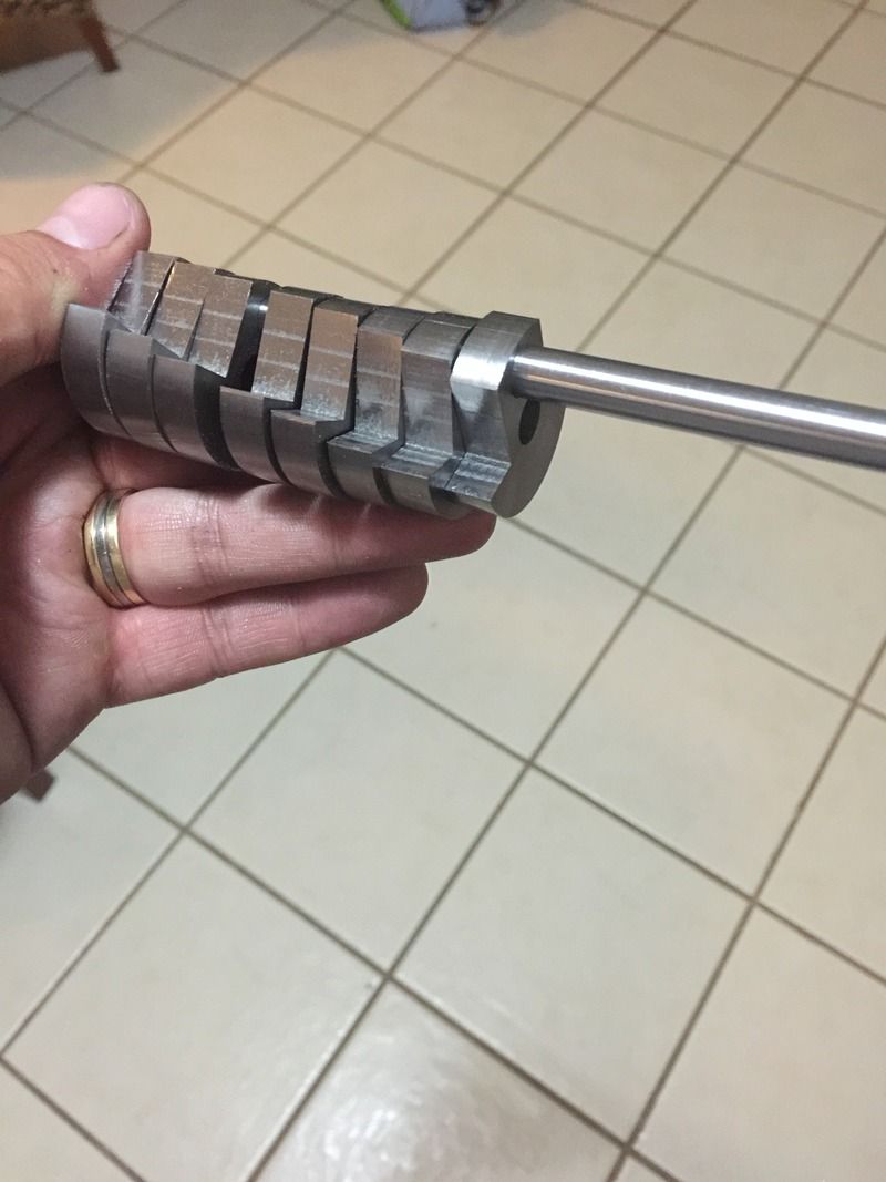
This is how things started.

Then milled to shape

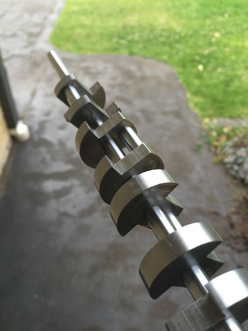
Then one end of the web was loctited in place. I used the opposite web and a shaft in the middle to hold it true while the loctite set. This pic shows all four 'throws' where only one web was loctited.

I cheated a little by not splitting the bushes for the big ends. Here I've installed them and loctited the opposite web to hold them in. Again used the shaft to hold it true.

This pic is where it's all loctited to one solid shaft. Bearings, spacers etc are all on. This shaft I turned down from a slightly larger diameter rod so I had a nice straight crank. Have not had any luck buying any straight shaft, even the cnc linear rod used for 3D printers that they claim is straight.

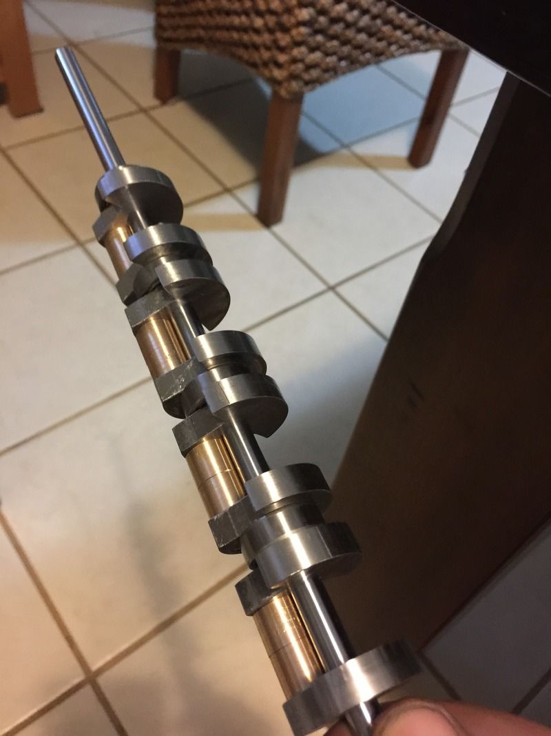
This pic I've milled out the required sections to get my final crank assembly.


Hope this helps.

Andy
 
I like it! My crank is a little more difficult because each cylinder has 2 opposed pistons, and one lags the other by around 15 degrees, so none of the crankpins are in line with any of the others - picture here of the first one maybe shows this a bit. In spite of this, loctiting all the webs to a single shaft would certainly help alignment and straightness.

Thanks a lot, you've given me plenty to chew on. Time to start making more swarf :)

Cheers
Martin

DSC04999 small.jpg
 
I just happened to be working my way through a pile of old MEW's rescued from a shed demolition job (no, I got there too late for the good stuff).

Issue 35 has a very good 11-page article on "Machining model crankshafts - materials, tooling and methods" and would be well worth rounding up a copy if you can.

It covers assembled and cast and one-piece machined crankshafts.
 
Many thanks, I'll see if I can dig up a copy. I am currently deciding whether to go down the 'machine solid bar between centres', or the 'fabricate with lots of bars which are then mostly sawn off ' approaches. Plenty of other bits to work on which I decide.

Thanks again
Martin
 
If you want to create an artificial crank, you can use a process of metal forming to as the forging process. In forging, a hot chunk of rolled cast iron is placed between heavy dies having the pattern of a crankshaft. The metal is squeezed into the crank's basic shape by applying extreme pressure from a forging press. The simplest crank forging dies are arranged in a single plane, which produces a crank forging that, has all the crankpins in one plane. To index the crank throws at 90 degrees, the raw forging is twisted to offset the journals in two planes to create the final raw crank blank.
You can use an improved forging process which includes forging the crank in two planes, so that all the journals are pressed into their final configuration. It eliminates the need to twist the crank to index the journals.
By using this method you get fewer internal stresses in the forging, as well as an improved grain flow in the cast iron. Crankshafts made with this type of tooling are called as non-twist forgings. Tooling for a non-twist forging is more complex and less durable than that for a simple flat forging. There is more excess material to be machined from such a blank to create a finished crankshaft. You can produce crankshafts forgings in huge volumes which are naturally gravitated to the lower cost and higher tooling life of a flat forging. These high-end non- twisted cranks can be easily used for many engines.
 
Thanks for that, Cynthia. Unfortunately, even the last 60 years spent in all aspects of mechanical engineering has not yet persuaded me to invest in a massive furnace and a set of drop-hammers - oh, and of course, a building to put them in. I suspect that it might be overkill for the single model engine that I'm building, but thanks for reminding me of a process that I first learned about in 1963 when a flying piece of red-hot slag off a drop hammer hit me just below the eye
 

Latest posts

Back
Top