Cam making basics

Home Model Engine Machinist Forum

Help Support Home Model Engine Machinist Forum:

This site may earn a commission from merchant affiliate links, including eBay, Amazon, and others.
It really depends on what type of cam you need. Simple single lobe cams are easy, but comlex multi lobe cams I have no idea about. What are you trying to build?
 
Hi All, this will help me too...I am busy with my first engine (Webster), and the cam making must be done in the near future. I have a Maximat V10 with milling attachment and rotary table in my little workshop available...
 
For a simple 1 lobe cam I just machine a blank to the major diameter of the cam,with the required shaft size in the centre. Then mount the blank in the rotary table / dividing head and mill a flat down as if I was going to reduce the blank to the minor diameter of the cam. So if the major diameter was 20mm and the minor was 15mm, I'd mill down a flat 2.5mm deep and lock the quill at that. Then simply rotate the blank 10 degrees or so, mill it and repeat. Eventually you'll have milled away everything except your lobe (the red bit in the shocking drawing below is what's removed), in a series of small steps that are easily blended with a file.

There are many other ways, and more experienced builders will post their methods I'm sure, but this is how I've been doing it.

Cam profile.jpg
 
For a simple 1 lobe cam I just machine a blank to the major diameter of the cam,with the required shaft size in the centre. Then mount the blank in the rotary table / dividing head and mill a flat down as if I was going to reduce the blank to the minor diameter of the cam. So if the major diameter was 20mm and the minor was 15mm, I'd mill down a flat 2.5mm deep and lock the quill at that. Then simply rotate the blank 10 degrees or so, mill it and repeat. Eventually you'll have milled away everything except your lobe (the red bit in the shocking drawing below is what's removed), in a series of small steps that are easily blended with a file.

There are many other ways, and more experienced builders will post their methods I'm sure, but this is how I've been doing it.

Hi Cogsy,

Thanks. This tip is J.I.T.(Just In Time) as I am about to cut the cam for "Webster".
 
Hi Cogsy, thanks seems quite straight forward. Now the mental planning can begin. Do you think EN36 is the right material for camshafts ? I happen to have it available..
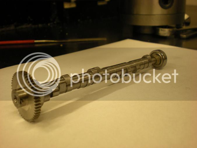
 
Hi Cogsy, thanks seems quite straight forward. Now the mental planning can begin. Do you think EN36 is the right material for camshafts ? I happen to have it available..

I honestly have no idea about metal selection at all. I use whatever I have available to me, if it wears out fast I'll do a bit more research when I rebuild it. Sorry, but I'm sure someone knowledgable will help you.
 
I make my cams from water hardening drill rod (W-1) I don't harden the cam but do harden the tappets if they are the flat type. If I use roller lifters I harden the roller.
gbritnell
 
Luc sent an excellent link to all the information one could need. There are no hard and fast dimensions for cam lobes. It all depends what one wants his engine to do.
gbritnell
 
I make my camshafts in the lathe using a simple fixture and excel spread sheet. I'll attach a file that will explain the whole thing. The artical covers a cam for a V4. Here are 2 others. They are all made using this method.


V8 cam


V twin


View attachment Offset turning the camshaft.pdf
 
Hi Putt-Rite,
I guess my method is very similar to Georges method but I use a program called CamCalc found at this web site.
http://modelenginenews.org/design/CamTable.html
This takes most of the math out of the calculation. There are parts of the parameter fields you must fill in, such as base circle radius, valve lift, flank radius, increments and it gives you a table very much like George's. starting at the base diameter as zero and amount of lift for each degree of rotation. You can have a fairly complex cam shape. On my Upshur single I used 2 degree increments and hardly needed to file the cam when I finished machining. I have never used it on anything but a single. Here is the best photo I have of the cam.
RawJan11366.jpg.html
RawJan11366.jpg
[/URL][/img]
Art
 
Last edited:
How would a simple wheel with a high spot work as a cam,even running a small bearing on the wheel so that the lifter will work smoothly and dependent on degrees of rotation covered by your raised spot you could time the length of time that the valve is open for.to obtain the right amount of movement at the valve you may have to alter the pivot point on the rocker to gain mechanical advantage. I am in the same boat no Cnc so this is how I plan to make my cam lobes. Just an idea
 
Here's another good article:

http://www.iskycams.com/degreeing.php

I find I have to read something like this, let it digest for a day or two, then read it again, etc, until it sinks in. I gather it's not hard to do or critical either. In fact, if I read it correctly, any overlap between 0 and 30 deg will run, in fact, the more overlap, the better.
 
if I read it correctly, any overlap between 0 and 30 deg will run, in fact, the more overlap, the better.


That depends on what your goal is. The more duration and overlap the harder it is to start the engine by hand. My engines have alot of both and will not start with a flip of the flywheel. I have to use a starter for RC planes to get them going. Not the end of the world for me but to somebody else it might be a problem. On the upside a low idle seems easier to attain on the multi cylinder engines.

No one cam is great for all engines.
 
I hand start RC airplane four strokes with 60° of overlap all the time. RC glow engines are started with a wet cylinder though and are easy to prime without flooding. Early engines built had little or no overlap. Overlap is mostly related to power. Because the valve takes many crank degrees to open, opening the intake valve before the piston is at TDC allows for the valve have greater open area when the piston begins downward travel. Later when tuning intake runners and exhaust headers became common this was used to further improve flow through the cylinder with overlap.

Greg
 
Sorry if this is a silly question....

Steve, I understand everything in your offset method guide (I think), except I can only count 45 cuts in any particular cam lobe column instead of the 47 calculated at the start of the guide?
 

Latest posts

Back
Top