(CAD) 28 Cyl P&W R-4360

Home Model Engine Machinist Forum

Help Support Home Model Engine Machinist Forum:

This site may earn a commission from merchant affiliate links, including eBay, Amazon, and others.
Ryan,

Not trying to dissuade you. I know where your coming from I can assure you. So does George and Steve.

I spent 13 years building a boat. If you want a bunch a people telling you "you'll never do that" or "Are you nuts?!"

Try building a steamboat....from the ground up. I got it worst from my siblings. I'm laughing now!

http://www.homemodelenginemachinist.com/index.php?topic=3198.0

If it's in your heart, go for it.

However, you did solicit comments...George was commenting, as was I.

Interesting thing about Forums...you only understand what has been typed

Glad you talked to Lee. The fixturing for the engines is tough to do from scratch. It's nice to get the drawing package with the manufacturing engineering done already! But I suspect you know that already.

We're a good bunch Ryan. We don't kick people when they're down, but help them up.

jump in and have fun.

Sincerely,

Dave

 
.
It seems I woke up on the wrong side of the bed. (I was still IN bed when I wrote my last reply). I apologize if I was 'snarky' in my last reply. My life has been riddled with people telling me I can't do something, and nobody has ever told me I can. It seems everywhere I go, I meet with resistance. But I digress.
I feel your pain bro. I guess I have been feeling a little snarky this weekend as well.

I know the feeling of being told no more often than I want to admit. Seems like a lot going on in life and lots to think about sometimes and often too little comfort and fun .
The best of luck with this project . I will tell you the same thing I told my son a few years back "If anyone can figure out how to do it you can" My son loved legos when he was younger he is 21 now. when he was IIRC about 14 he wanted to build a working air powered engine built from legos. I he wanted me to figure it out for him . I did not feel like I had the time and energy to figure it out at the time. and I told him that as well he did figure it out the engine runs it shows up at shows and is in the gallery on the FAME site. sorry it does not link well.
I sometimes quote the old possibly Chinese saying
"Those who say it can not be done please do not disturb those doing it. "
I would thing the biggest challenging will be the crank case. the crank shaft not too bad. the pistons cylinders con rods valves etc. you should get real good at lots of copies of each .
Tin
 
Not much work today on the 4360 'Wasp Major Mini'. I'm at the first of many roadblocks. Having designed the basic layout of the crankshaft, the next logical step would be the master rods. In themselves, the master rods aren't particularly complex, though certainly more complex than what you might expect of a smaller radial. Each master rod is identical, composed of two pieces split horizontally and joined together by 4 vertical bolts. These bolts pass through the plane of two of the link rod pins, the bolts have holes drilled in them to accommodate the pins passing through.

The issue here is that I don't have much to go by for the dimensions. While I had a good drawing of the crankshaft with which to make my measurements and scale, I only have a 3/4 view photo of a real master rod to go by. this view doesn't permit me much in the way of dimensions, and I've no idea what the scale is. I'm going to have to do a lot more guesswork to get this component right. Further compounding the fact is just how much of a load this component is under. The full scale engine transmits upwards of 1100 to 1500 horsepower through each master rod... improper design will easily lead to failure. The last problem is that a rod's length is only loosely determined by the stroke of the engine. One of my I.C. Engineering books suggests the ratio of the connecting rod length to the crank radius should be in the 3-4 range for 'smaller' engines (though the book's idea of 'small' is more on the scale of automobile engines). since my crank radius is the same as my stroke, this means a connecting rod length of 3 to 4 inches. A longer rod makes for a slower engine (if you disregard many other factors).

The rod length drives my cylinder length, by way of deriving compression ratio from piston travel... so another component I could focus design on is the piston... Pistons around the world have the same basic conceptual shape. This engine in particular uses a domed-head piston in a hemispherical combustion chamber, compounding the math for the compression ratio, but nothing beyond my capabilities...

Just trying to decide where to go next... sigh, I hate decisions.

More later
- Ryan
 
Hi Ryan,

Do you know the crank pin diameter? ( I think you said you had a good reference for the crank)

Secondly, do you have a reasonable scale view of the rod? with the crankpin bore?

If you know that diameter, you could scale the rest. It should get you close and the length can be adjusted later once you start laying in the top end of the cylinders...don't put too much detail in yet until you get the pistons and the cylinder top end laid in..A stick figuire right now would suffice until the rest of the parts are "doped out"...just a thought.

Dave
 
by the way, a longer rod will reduce your piston peak acceleration and decrease your side load on the piston skirt.

As long as they don't buckle, a long rod won't hurt you.

Dave
 
I'm sorry if you hurt your feelings, that certainly NOT my intention - au contraire - I was only pointing a step by step approach to achieve what you set out to do.

If all the steps are small enough, they are (normally) all doable and all within reach.

I will certainly continue to follow this thread. All interesting threads here are bit like brainstorming and that has always been a part of the process (several times along the way) of the best projects I've been part of - I'll NEVER be able to make as good construction by myself as I has, when part of a team. And even if I can't contribute - I'll still learn something ;)
 
Hi Admiral

None other than Harry Ricardo used that approach on every new concept engine...single cylinder test bed first.


Dave
 
Dave, I estimated the crankpin diameter as c/t the crankshaft (referenced as the 'master rod journal') as approximately 0.435 inches. However, the engine uses bearings in between the master rod and its journal. I realize many scale engines don't use the bearings, because they're not used so much that wear and tear is really a concern. I'm still fighting over the idea of using bearings on mine. It would certainly be FAR easier not to!

The only images I have to go by for the rods themselves are below. (I think. this is the first time i've tried 'attaching' images instead of inlining them. they're bigger)

masterrod.jpg


linkrod.jpg
 
Admiral,

Think nothing of it. We'll just sweep those metal shavings under the rug. I was just in the wrong mood this morning when I read the replies. I get over things quickly, and am in a rather more upbeat mood today. Ironically, I hadn't fully understood the gist of what you were suggesting back on page 1, and it turns out I'd already more or less planned on that route, to a degree.

It had occurred to me that machining 28 cylinders worth of engine and putting them all together and seeing if it would run, wouldn't tell me WHERE a problem existed in all that metal. If I had binding, or uneven firing, or NO firing, or any of the multitudes of issues that could happen with a running prototype engine, it would be next to impossible to figure out which cylinder was at fault. So my idea is to build a test rig, on which EVERY cylinder will be tested before it is moved to the Wasp Major 'Mini'. In this way, presuming the test rig works, I will both be 'running in' each cylinder/piston/valve set, and ensuring they're machined properly before putting them in a place where it would be much harder to isolate problems with them.

I had also thought it could be interesting building them into a 7, then a 14, etc. this way i can machine a few at a time and avoid the tediousness of making 28 or 56 of every part!

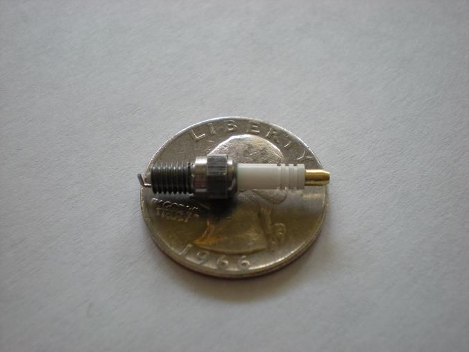
I will require some input from the forum in the area of spark plugs. If I were to try and purchase Rimfires for this machine, and kept the 2-sparks-per-cylinder of the full scale, then it would cost me well over $1000 for the spark plugs alone. This cries out for making them myself, and I've seen several posts by others where they've had success at doing so. I hope to ask for help in that area when it comes time.
 
As a kid living in Ft Worth Tx at the end of WWII, it was not uncommon to see and hear, flights of 100 or more B-24 Liberators overhead as delivery flights formed up leaving the Consolidated Aircraft plant. These planes had four of the Pratt & Whitney 14 cylinder radials. What a sound. Made your heart pound. And the silence as the last plane faded from sight was deafening. A few years the B-36 took to the air with six of the 28 cylinder engines. They were never produced at the same rate as the B-24 but we did see flights of six aircraft at a time. Even just six aircraft meant that over 1000 pistons were thundering over. This plane had high altitude capability and introduced the world to the sight of contrails in the clear blue sky.

There is nothing to compare with the sound of a big radial engine or lots of big radial engines.

Jerry
 
Rayanth said:
I will require some input from the forum in the area of spark plugs. If I were to try and purchase Rimfires for this machine, and kept the 2-sparks-per-cylinder of the full scale, then it would cost me well over $1000 for the spark plugs alone. This cries out for making them myself, and I've seen several posts by others where they've had success at doing so. I hope to ask for help in that area when it comes time.

Many here have made them so you will have many options in that department. What scale will this engine be designed to? I have plug designs down to #6-56. I have made plugs for the Demon at #8-40 thread


Regarding the bolts and link rod pins, wouldn't it be far easier to drill holes in the link rod pins and pass the bolts through them than the other way around? That way the pins would be captured and there should be very little if any end play.

Ron
 
Rayanth said:
Dave, I estimated the crankpin diameter as c/t the crankshaft (referenced as the 'master rod journal') as approximately 0.435 inches. However, the engine uses bearings in between the master rod and its journal. I realize many scale engines don't use the bearings, because they're not used so much that wear and tear is really a concern. I'm still fighting over the idea of using bearings on mine. It would certainly be FAR easier not to!

The only images I have to go by for the rods themselves are below. (I think. this is the first time i've tried 'attaching' images instead of inlining them. they're bigger)


Ron Colonna uses sheet silver in his Offy for bearing inserts. Apparently this was the "cats backside" on racing motorcycles and some air craft engines. He used .010 thick sheet. His book on the Offy is a GREAT read by the way...hint hint. ;D
No way connected, just thankful for the education I got from his book.

Silver is the best bearing material there is according to some and I know most of our WWII radials had silver lined inserts.

0.435 is damn close to 0.4375....It's easier to find those reamers... ;D


Dave
 
I brain-farted when I made the calculation in my head. I knew there was a .43something... I'll make the change, very simple to do. The 4360 did indeed have silver-lined bearings which were subsequently lead-indium plated as well.
 
stevehuckss396 said:
Many here have made them so you will have many options in that department. What scale will this engine be designed to? I have plug designs down to #6-56. I have made plugs for the Demon at #8-40 thread

Steve, it's a 1/6 scale, but at the size of this machine that might mean something different to you than it does to me =) As noted in my crankshaft post, the crankshaft alone is 7.2 inches long.

In terms of the spark plug, the piston has a .958 inch bore and 1 inch stroke. give you an idea of the size of spark needed - my own experience in that area is quite limited.

- Ryan
 
Rayanth said:
Steve, it's a 1/6 scale, but at the size of this machine that might mean something different to you than it does to me =) As noted in my crankshaft post, the crankshaft alone is 7.2 inches long.

In terms of the spark plug, the piston has a .958 inch bore and 1 inch stroke. give you an idea of the size of spark needed - my own experience in that area is quite limited.

- Ryan

At 1/6th anything will look to big. smaller the better but . . . the smaller the harder to make and reliability might suffer.
when you get to the point where the head is designed, I'll send some cad files and you can see what they look like.

DSCN1827s.jpg
 
Dave, am I mistaken in understanding that you're suggesting making the bearings myself? :eek: I didn't think was possible...

- Ryan
 
YUP!

Colonnabearing.jpg


That's the concept anyway...

If you have doubts...click on Ron's web page under "Listen to it run"

Dave


Back
Top