Building the Trevithick engine

Home Model Engine Machinist Forum

Help Support Home Model Engine Machinist Forum:

This site may earn a commission from merchant affiliate links, including eBay, Amazon, and others.
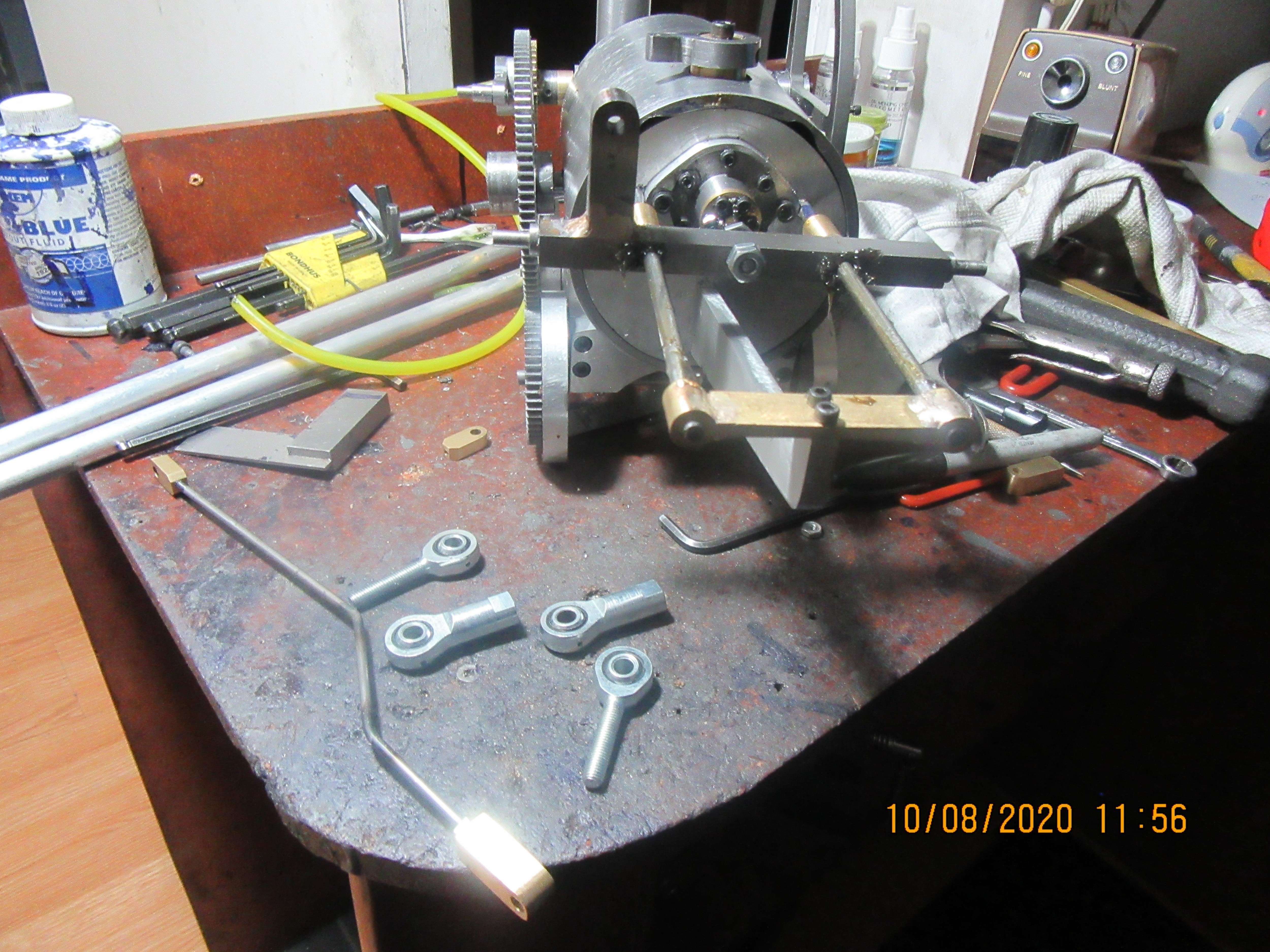
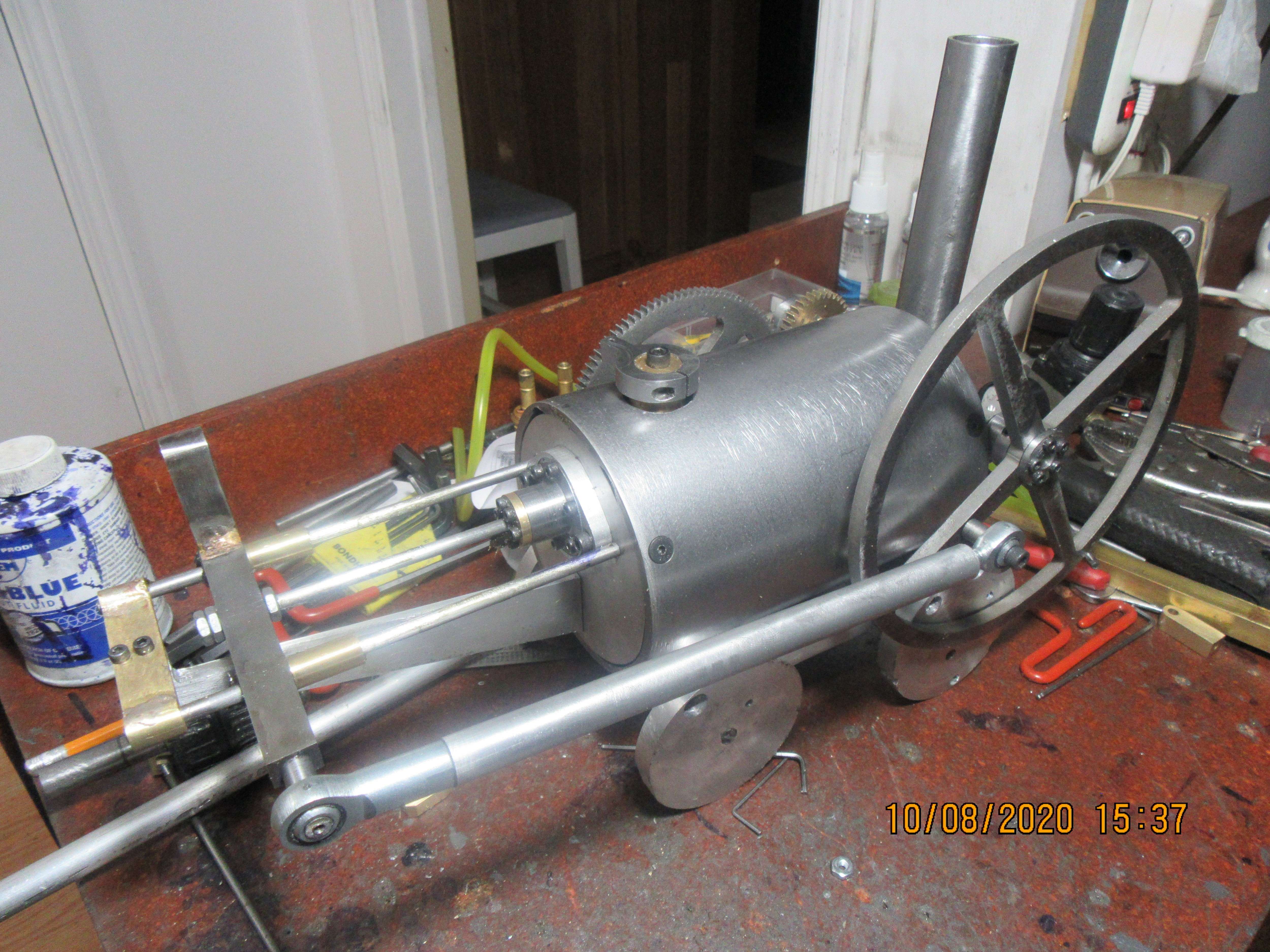
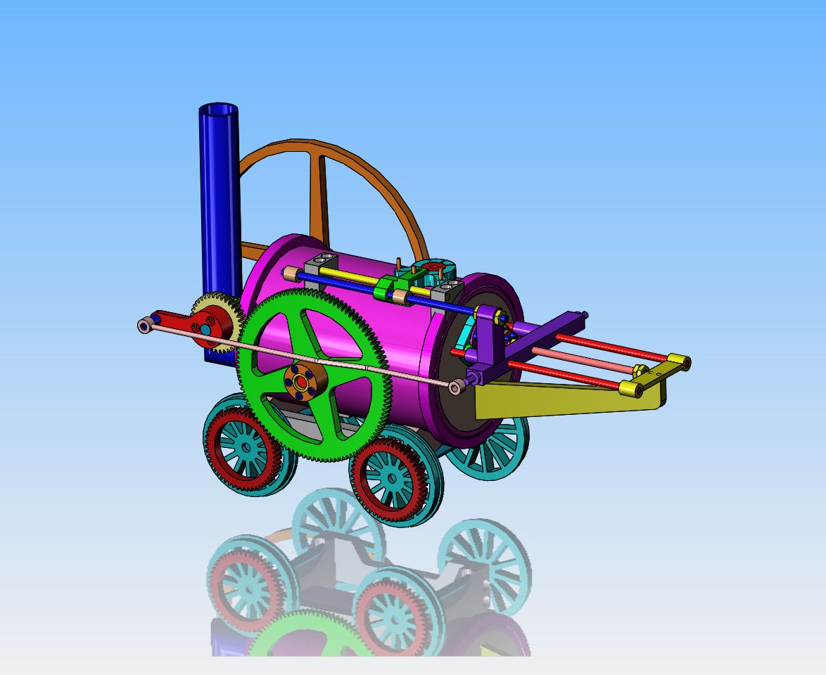
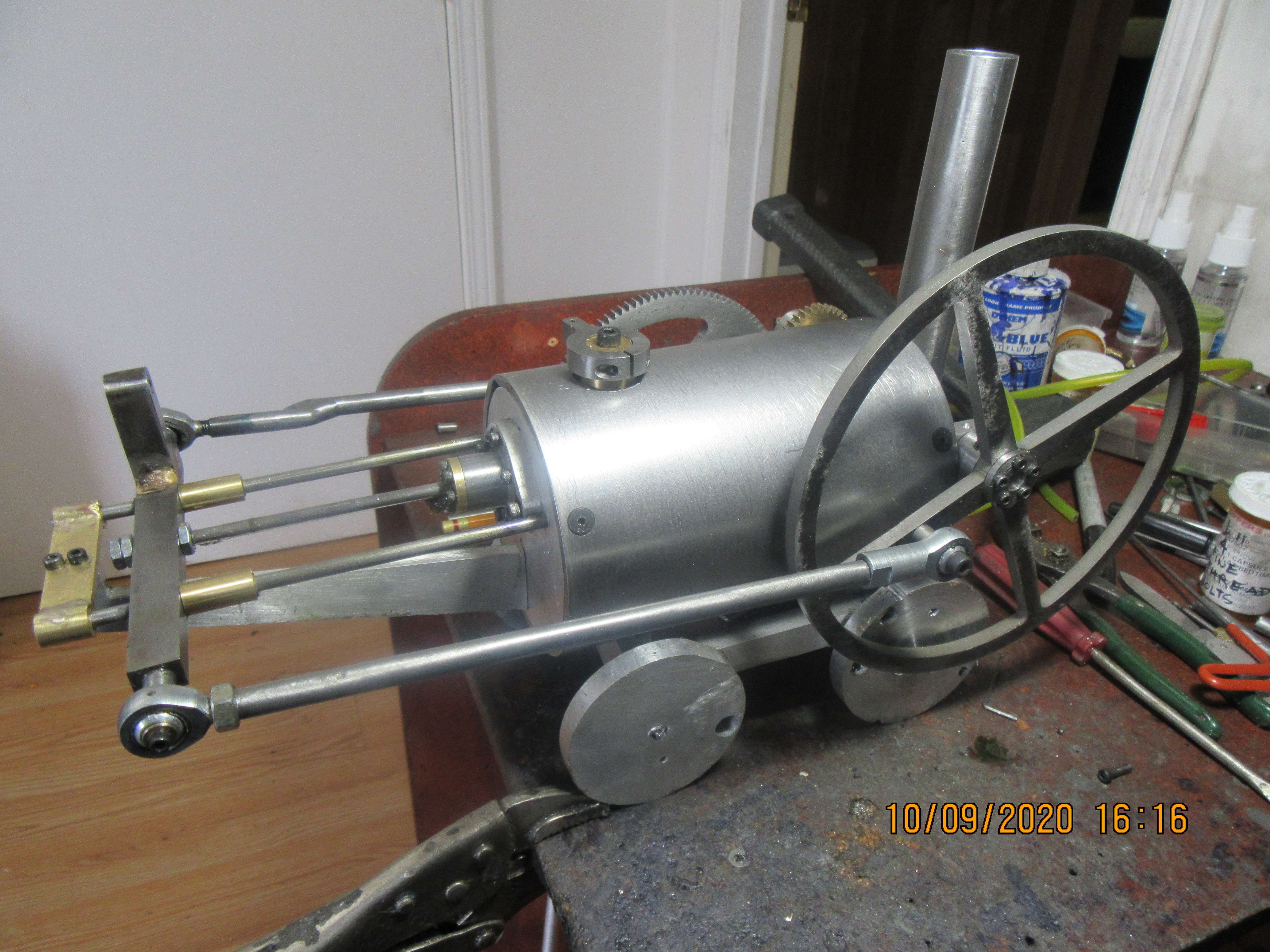
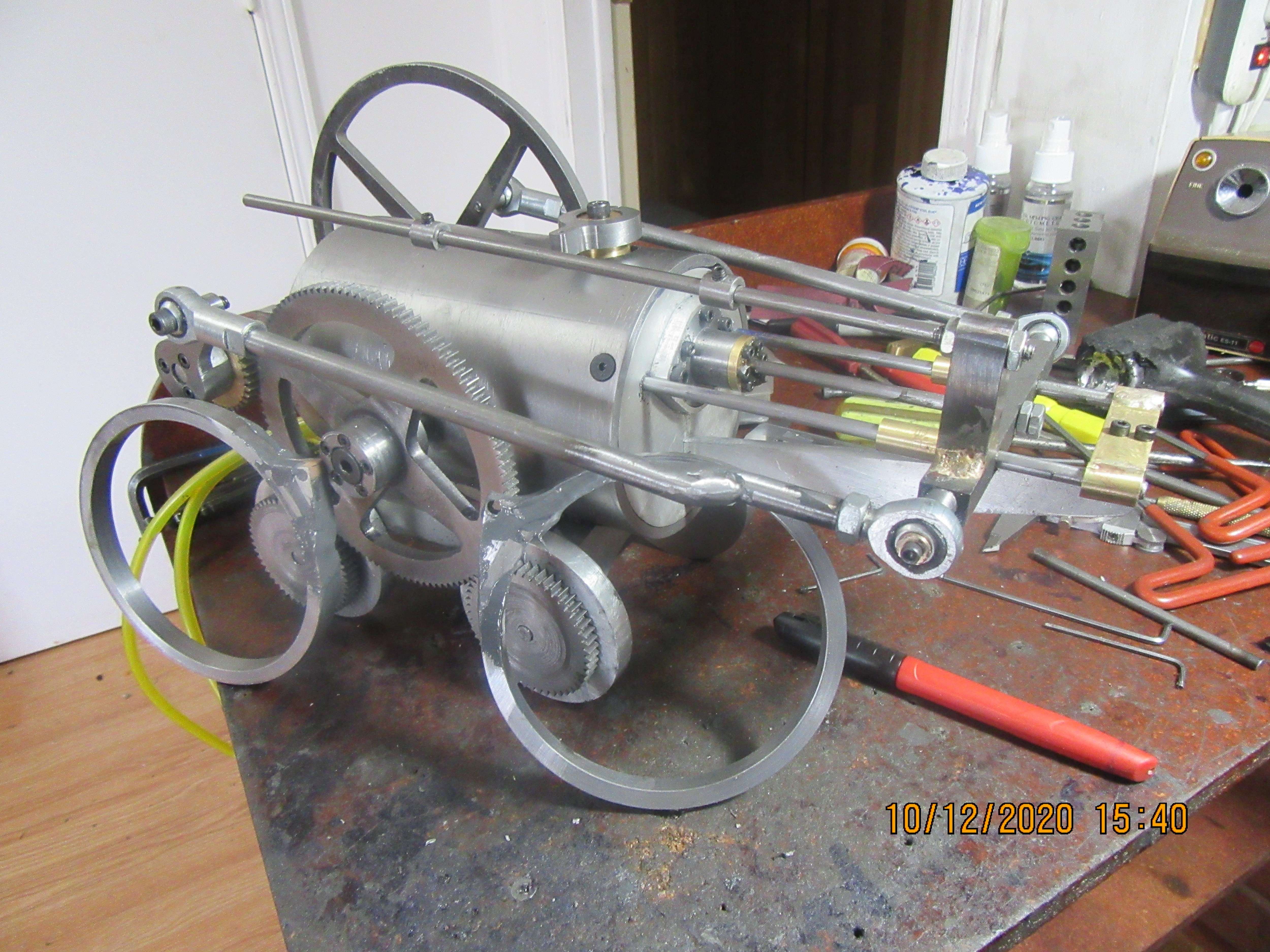
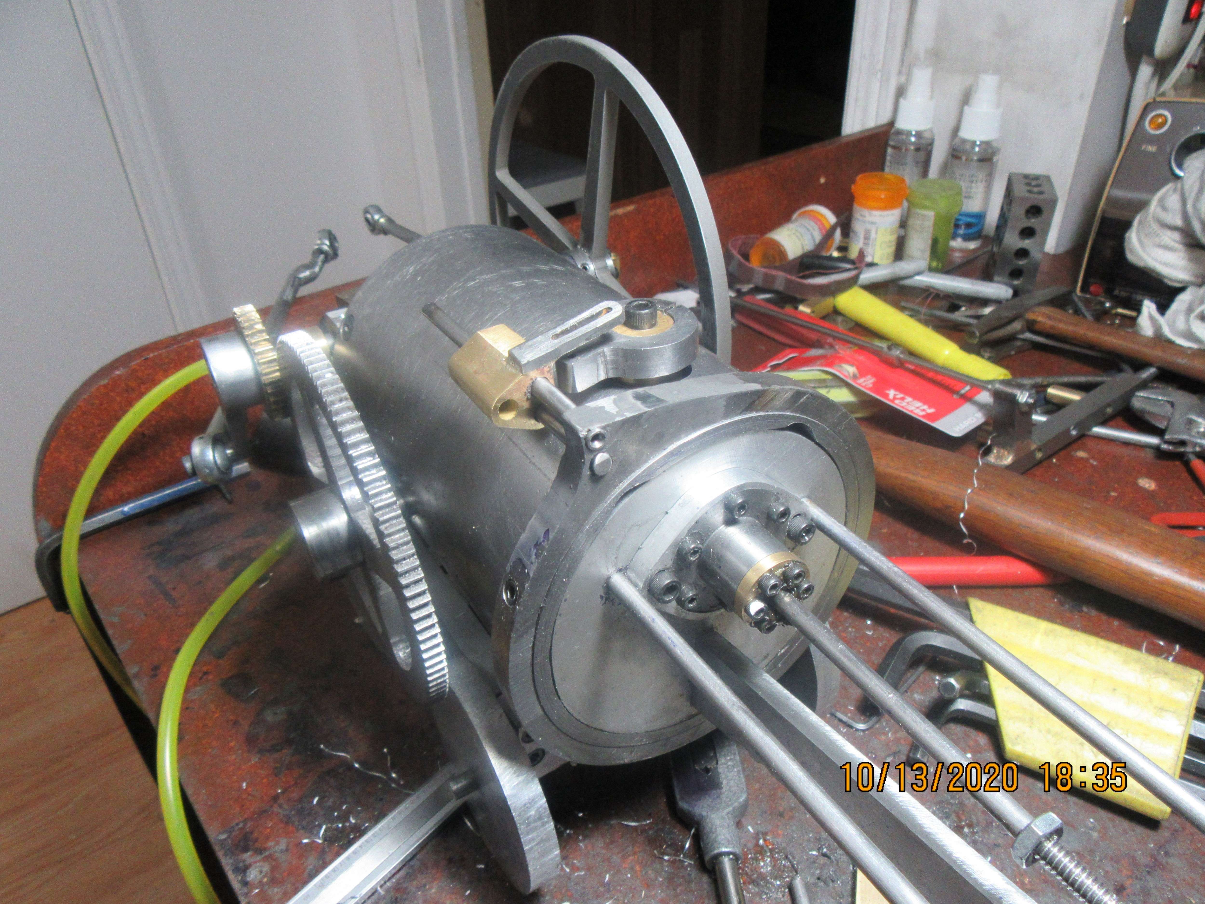
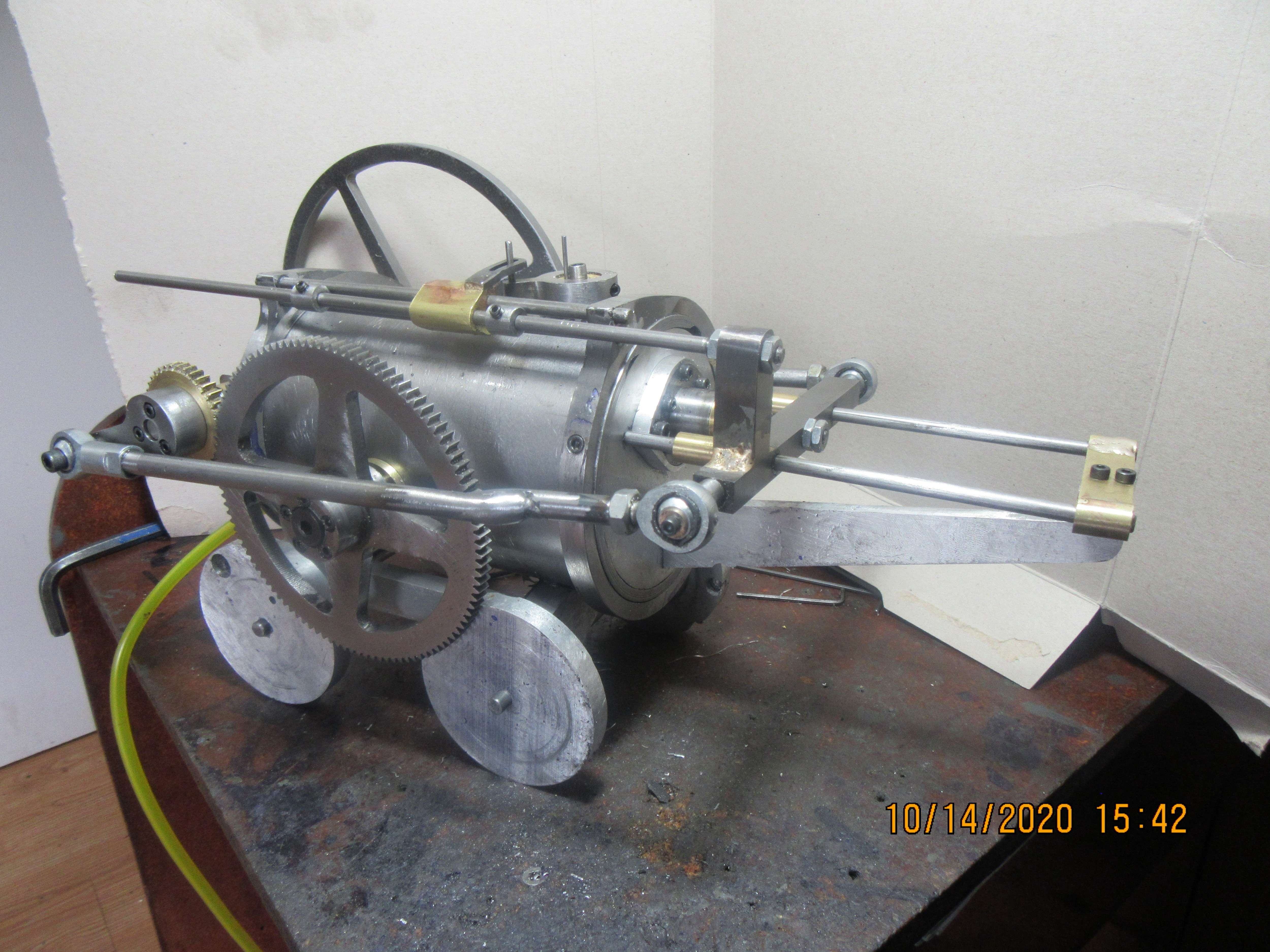
Today was a day for fettling and fitting. The new elbows on the 4 way valve gave me the clearance I needed, so I was able to bolt the end with cylinder attached to the boiler. I routed the air supply hose from the 4 way valve to the hose barb in the back plate, and routed the exhaust thru the backplate and into the smoke stack. The only new part machined today is the arm attached to the bronze gear which sets on the flywheel shaft. I'm hoping that my local nut and bolt store has 3/16" shoulder bolts, which will attach the "connecting rods" to the new arm and to the flywheel. I'm thinking that the boiler would look a lot better with a flange at each end. I may buy some material to add a flange to each end of the the boiler.
5R1NN3.jpg
 
If I had some 1/8" rod bent and threaded, I'd have connecting rods finished. The four brass ends are shown in place in this picture. I've got so much junk on top of my "assembly table" hat it's hard to see. Tomorrow I'll make and install connecting rods.
IkUTIs.jpg
 
It's time for a change in my game plan. I had originally planned on using 1/8" diameter cold rolled steel round-bar with soldered brass ends for connecting rods. Tried that yesterday, but found that 1/8" is far too skinny and bendable. not going to work. Went out today and spent some of the Rupnow fortune on spherical rod ends. The con-rod diameter will now match the o.d. of the female rod ends.
jZnZJK.jpg
 
Here we have the "heavy con-rod" on the non gear side, with a spherical rod end on each end. As things work out, the con rod on this side doesn't really need an offset, which is fine with me. Tomorrow I will work on the gear side con rod, which definitely will have an offset in it to clear the hub on the 108 tooth gear.
MftsrC.jpg
 
Couple of things I should mention.-- That new con-rod is way too large in diameter, but it won't deflect under load, and once the engine is running it will be replaced with a smaller diameter piece.--And--I picked up a piece of material today large enough to create "flanges" for the ends of the boiler. I think that if these boiler "flanges" are added they will do much to make this model look more like the original Trevithick engine. It's a bit difficult to imagine with the 3D model being more colors than the rainbow, but I think it will look better.
9keSFr.jpg
 
Brian,

Just gotta check in to say I'm liking this project and your usual approach to finding a way to get it all done.
I also like that you're trying your hand at making a vehicle this time (although I remember the little cart that was tethered by its air line and ran in circles.)

BTW, Just can't resist mentioning that your crowded table includes the proverbial Bigger Hammer.

--ShopShoe
 
I couldn't stand how big and clunky a 1/2" diameter con rod looked. Today I made new con rods from 5/16" diameter cold rolled steel to replace the first one which was 1/2" diameter aluminum. Everything looks a lot more proportional now. Video to follow when my camera battery is charged.
4bfq6u.jpg
 
Sometimes the game plan changes in the middle of the game. I originally did not intend to have flanges at either end of the boiler. Last week I decided I actually did want them, as separate rings that I could slide over the ends of the boiler and attach with small bolts. The only fly in the ointment was that I had already dedicated the space at one end of the boiler to support a guide rod mechanism for the slider that moves the valve. Today, I turned up some plate on my faceplate to get a curvature identical to the o.d. of the rings (one of the rings is leaning against the headstock in the picture), and then welded the resulting pieces to the rings. My tig welding is improving, but it is not very artistic. So, at this point the pieces are welded to the rings, and the resulting welds are slathered with J.B. weld which won't be dry until tomorrow. When they have dried, I will work some artistic magic on them and then attach the rings to my boiler.
yzw05X.jpg
 
No real machining work this morning, but a couple of hours spent updating the 3d model to reflect what was actually built. Here you can see the heavier connecting rods and the updated boiler rings which have the guide rod supports built into them.
Wq947w.jpg
 
Spent a very large part of the day working out tight spots and freeing everything up. This is a finicky kind of job, and it can't be done until everything is almost finished and assembled. Also got a start on the valve valve actuator rod. The two rings which go on the ends of the boiler are leaning up against the engine.
mtTSNc.jpg
 
Hi Brian,
Another lurker enjoying your progress. excellent stuff.
Given that the original locomotive managed a velocity of around 5 MPH, do you know the RPM the engine was doing?
( It should be possible to calculate if you know the wheel diameters and gear ratios )
Cheers,
Fred B
 
phred--no, I really don't know. In any videos of the Trevithick that I have seen, it runs very slowly. As a general rule, models run a bit faster than the original engine, but I don't know how fast it will run.
 
Elvis has not left the building. Elvis is up to his neck in adding the flanges to the boiler and adding the valve linkage. I really, really hate making changes part way thru a job. I can make it end up pretty, as if I'd planned it this way all along, but it adds a whole page to my frustrations list. Oh well, one end is finished. Tomorrow, who knows?--The canary may sing for me!!
yposWV.jpg
 
Mechanically, I'm at about 99%. I can tell, after playing with it half the day, that it wants to run. It is proving very difficult to set the 4 way valve so that it reverses the action of the cylinder at the end of the stroke. I've about had it for today, but wish me luck for tomorrow.
qta4zI.jpg
 
Game plan for tomorrow is to broach keyways in the flywheel, bronze gear, and crankshaft. Right now they are only connected with set screws, and the two offset pinions keep getting out of synch and locking things up.
 
Keyways have been added to the flywheel, bronze gear, and to the crankshaft. It helps, but still doesn't let the engine get "over the hump" at each end of the stroke and continue running. Once an engine like this runs, it quickly wears down any "tight spots" and the longer you run it, the smoother it gets. Of course, the magic is in getting it to a point where it will run under it's own power. There really aren't any more changes I can do mechanically to get it running. This leaves me with two options. Make a bigger, heavier temporary flywheel to get it running, or hook it up to an electric motor and let it run for a couple of hours to get rid of any remaining tight spots. The electric motor method is the cheapest, since I don't have to buy any material, but this is not an easy beast to hook an electric motor to. I am going to call my metal supplier and ask about the price of a 8 1/2" square plate x 1/2" thick to make a much heavier flywheel.
 
Now you know how I spent my afternoon. This started life as a piece of 1/2" x 8 1/4" x 10" hot-rolled flatbar. There is no center hole in it yet, just a good center-punch mark. It has double sided tape on the side facing the lathe jaws and is held in place by a live-center in my tailstock. I cut the 4 corners off with my bandsaw and then spent the afternoon nibbling away at it until it is perfectly round. This method always works well for me, but you can only take about 0.010" depth of cut or the tape slips. I'm not going to put a lot more time in this flywheel. Tomorrow it will get a centerhole and keyway and set screw, and have a #10-24 thread put in 1 1/2" off center for the shoulder bolt which connects the con rod. If the heavier flywheel does the job and makes the engine run, I'll worry about doing some cosmetic work on it later.
m8dVX3.jpg
 

Latest posts

Back
Top