You are using an out of date browser. It may not display this or other websites correctly.
You should upgrade or use an alternative browser.
You should upgrade or use an alternative browser.
Building the Trevithick engine
- Thread starter Brian Rupnow
- Start date


Help Support Home Model Engine Machinist Forum:
This site may earn a commission from merchant affiliate
links, including eBay, Amazon, and others.
Thanks Bighoss.--There is certainly a lot of steps involved. If I was rich instead of good looking, I'd have had the gear water-jet cut.---Brian
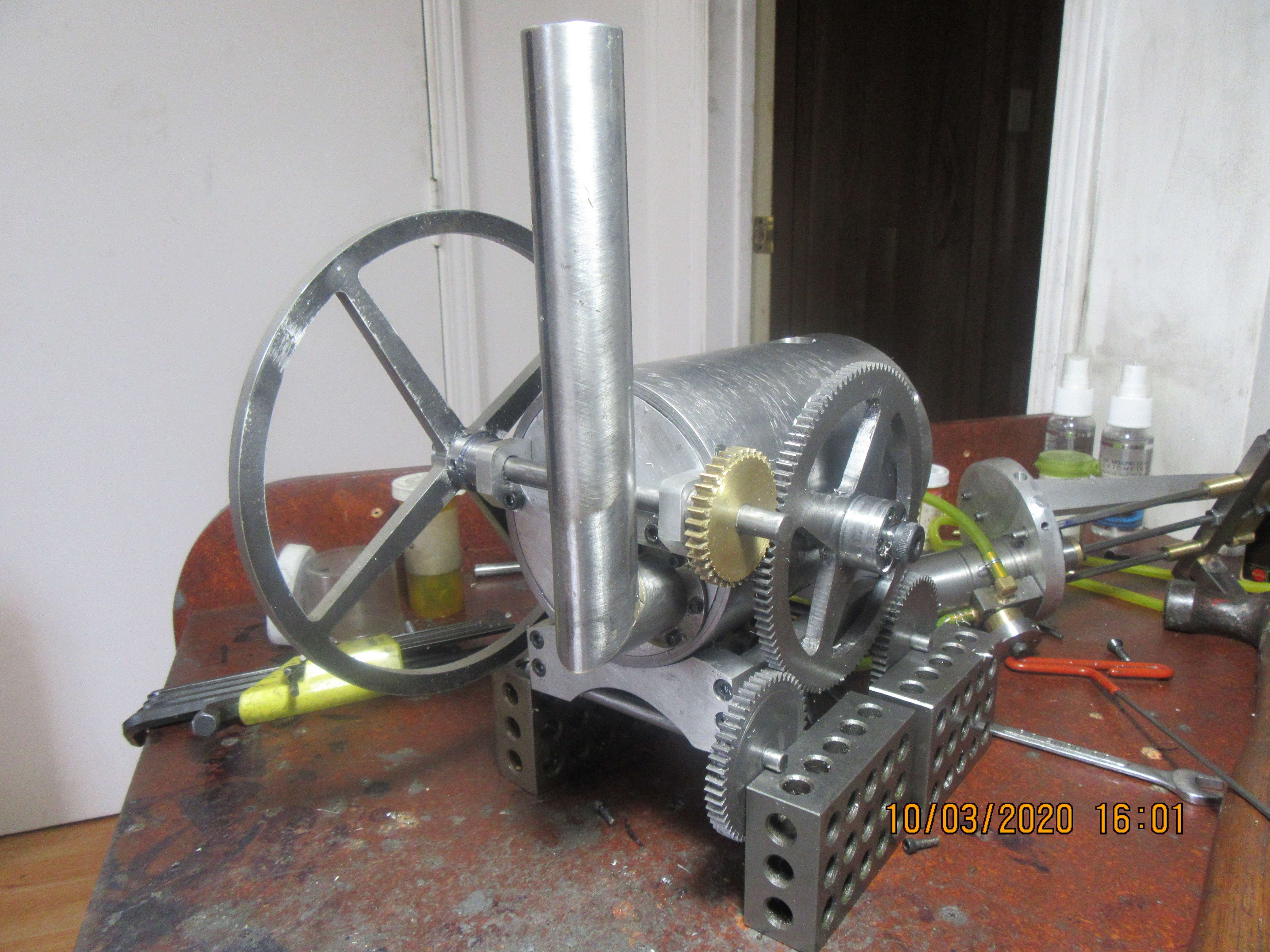
And that, my friends, is a beautiful thing. I have a new description of anxiety---It's that feeling you get when you've finished the 108th tooth and you move the rotary table one more step, and take a final pass to see if you are cutting metal or air. All went well.
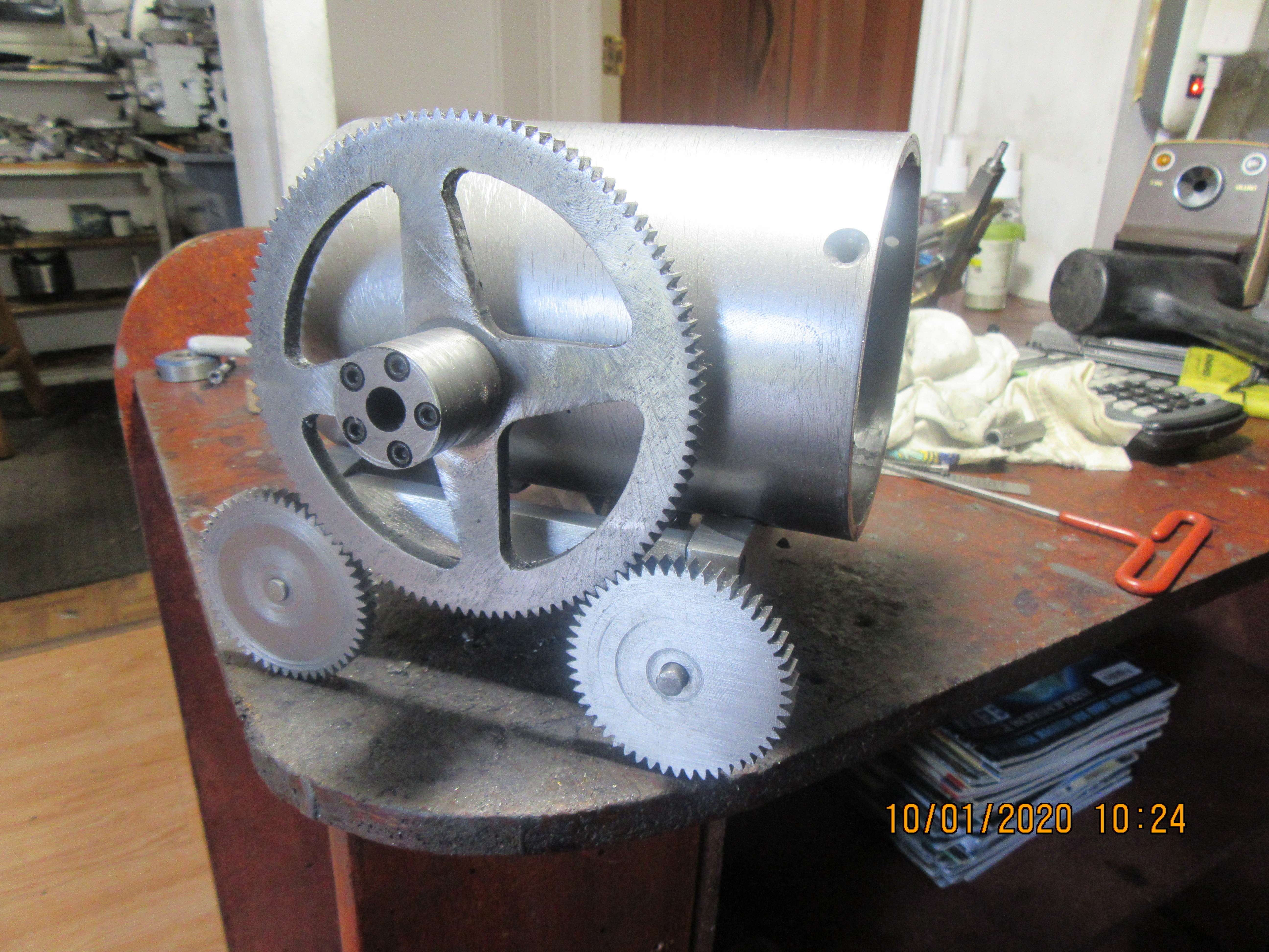
It's never quite as easy as I think it's going to be, but I like this. I tapped the side of the boiler and installed the big gear with a 3/8" shoulder bolt. Sid had commented that I should have used gears with a larger, coarser tooth, but I think this doesn't really seem that far out of proportion.
Davidl--Thanks for saying Hi. I enjoy designing and machining so much, and I do like to share the steps involved with others. I love it when folks step by and have a look and leave a comment.---Brian
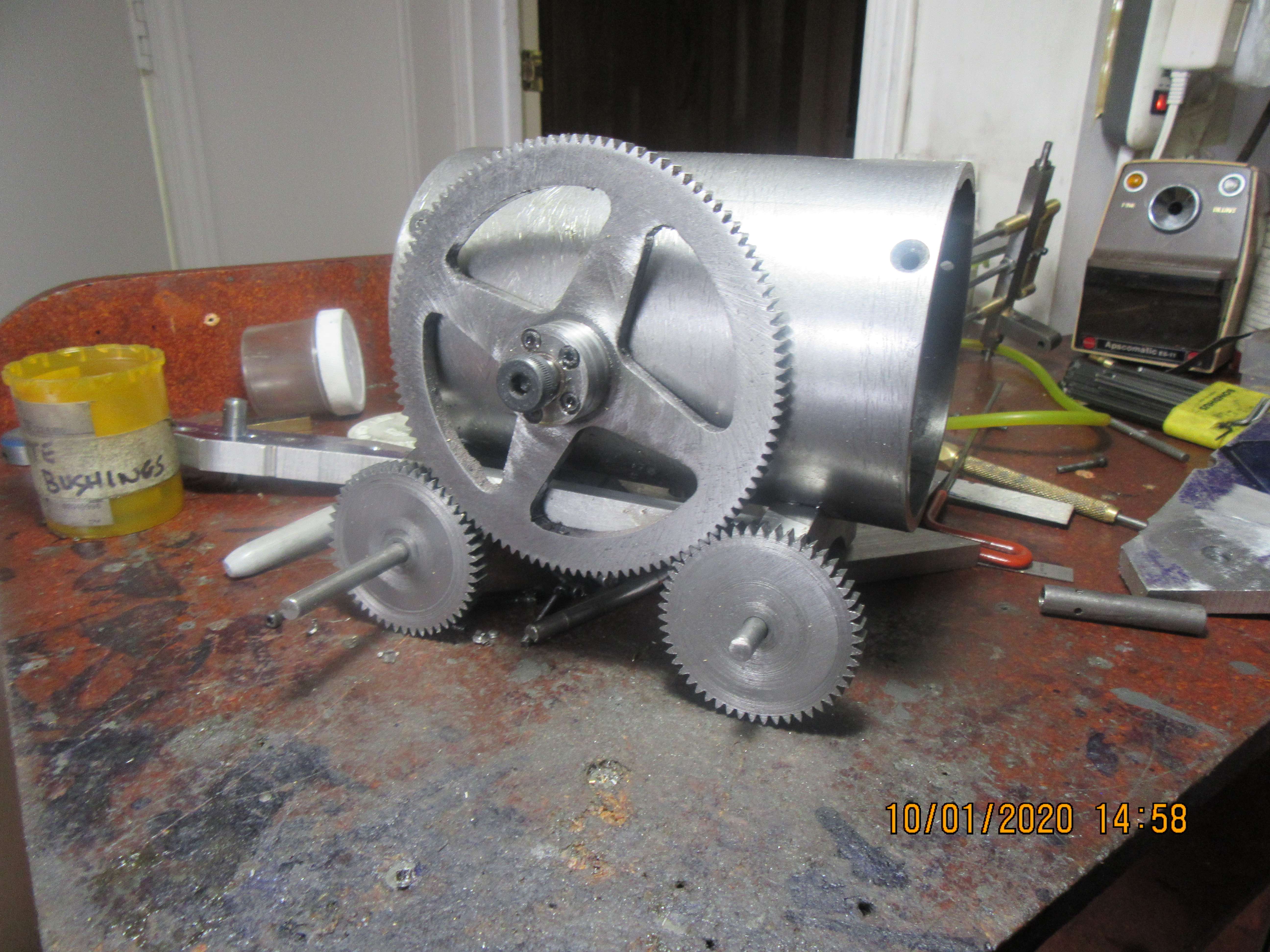
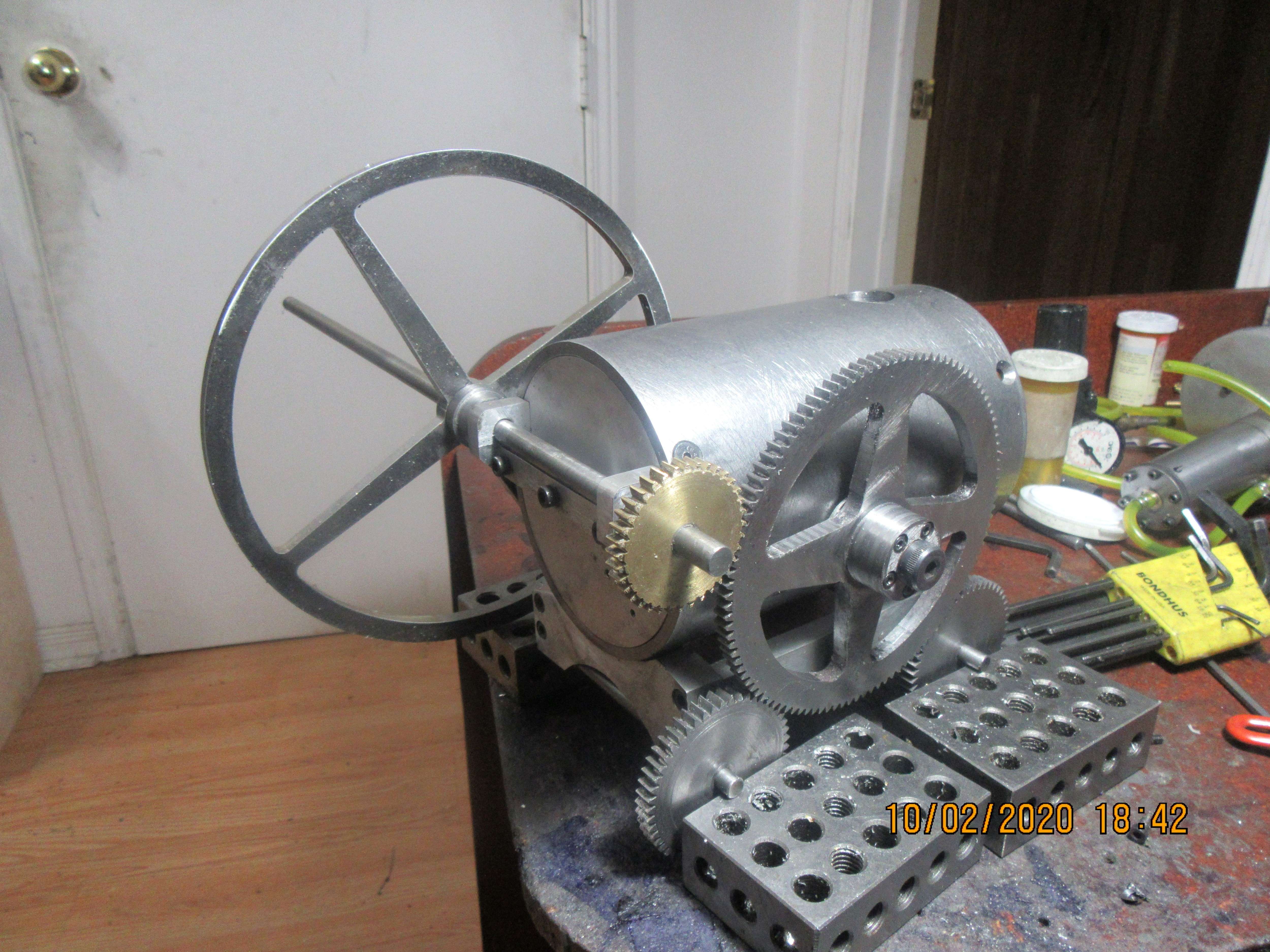
I was hoping to post a short video of all the gears and flywheel turning, but I didn't quite make it. My butt is absolutely kicked for today. Tomorrow I'll put a set-screw in the flywheel hub and make a short video. It has been a day long thrash here, but I'm happy with what I've accomplished.
Looks good Brian, At the moment I would only got half of that done before I was kicked for the day
Cheers
Andrew
Cheers
Andrew
thegallery
Junior Member
- Joined
- Apr 21, 2013
- Messages
- 37
- Reaction score
- 91
I built this model during the past year. You can see more at: www.thekilmerplace.com

And, as promised, here is a neat video of all the gear-train and flywheel in action.
To the "Gallery"--Your model is wonderful. It is obvious that you put a great deal more effort into your model than I have. Congratulations on a beautiful and well crafted machine.---Brian
After yesterdays hard slog, I wanted something a bit less critical to make today. A smoke-stack!!! Has to be visually appealing but no real finicky sizes and meshes involved. Good stuff!!! All I need on this end now is a faux burner door and a spigot to get my compressed air inside the machine.
- Joined
- Sep 2, 2011
- Messages
- 1,342
- Reaction score
- 360
Brian, ive been watching and wondering about the gear ratio on the drive. thats a whole lot of BIG to little from what learned playing with my legos back in the 70's early 80's. where i first learned about gear ratios. but from that lesson BIG to little means fast and power robbing. - i guess i just want to know more about this situation or even if you feel this is a situation(such as but not limited to - to fast or not enough hp to move it). (discusssion mode here not saying bad or anything) ive been holding back on asking but curiosity has got this cat....
Best answer--The brass gear which is attached to the "crankshaft" is little. It drives a "big" gear. That means that the big gear will rotate more slowly, but will develop considerably more torque. Speed and torque are diametrically opposed--one goes up, the other comes down and vice-versa. The big gear turns two smaller gears, so they rotate faster, but lose the torque benefit. If I was designing something from "scratch" I wouldn't do it this way.--But remember, this design was first established 215 years ago. People were designing all kinds of new machinery and there wasn't a clearly defined method behind what they were doing. People designed a lot of new mechanical things that ultimately failed. If something failed, they didn't do it that way the next time. If something was a success, then the design was copied and refined.
The ratio is drivers / driven - the big wheel has nothing to do with the ratio - its as if the brass gear was directly driving the wheel gear - the big wheel is just an idler and means of transmission.
Regards, Ken
Regards, Ken
Brian,
Just terrific, marvellous work. On behalf of other lurkers like myself, please keep posting.
Regards,
Andy
For anyone interested in the Beam Engines at Pool shown in the Mark Williams videos:
https://www.nationaltrust.org.uk/east-pool-mine
Just terrific, marvellous work. On behalf of other lurkers like myself, please keep posting.
Regards,
Andy
For anyone interested in the Beam Engines at Pool shown in the Mark Williams videos:
https://www.nationaltrust.org.uk/east-pool-mine
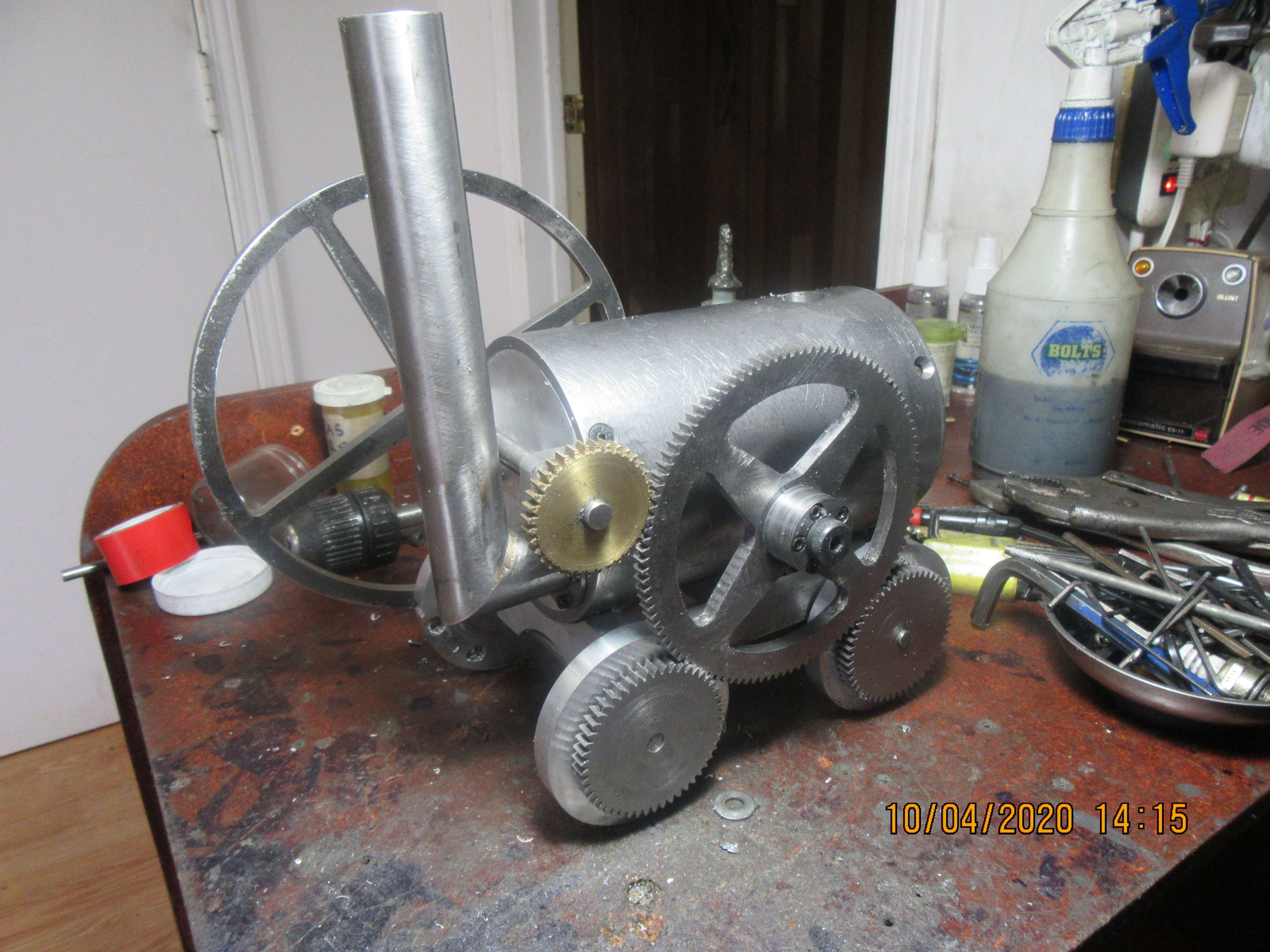
Today I had to make 4 temporary wheels for this thing. They are the same diameter and thickness as the finished wheels will be. I can keep track of where things should be and how to make dimensional allowances for it up to a certain point, and then I start to lose bits and pieces. This way keeps me on track, one less thing I have to be thinking of and remembering. These wheels were made from scrap pieces of 3/8" plate. Also, I machined an air inlet tube and screwed it into the back-plate just to the left of the smoke stack. It is a cold, wet, and dismal day here and I'm about to head upstairs and lose myself in a good book.

Mechanical evolution!Best answer--The brass gear which is attached to the "crankshaft" is little. It drives a "big" gear. That means that the big gear will rotate more slowly, but will develop considerably more torque. Speed and torque are diametrically opposed--one goes up, the other comes down and vice-versa. The big gear turns two smaller gears, so they rotate faster, but lose the torque benefit. If I was designing something from "scratch" I wouldn't do it this way.--But remember, this design was first established 215 years ago. People were designing all kinds of new machinery and there wasn't a clearly defined method behind what they were doing. People designed a lot of new mechanical things that ultimately failed. If something failed, they didn't do it that way the next time. If something was a success, then the design was copied and refined.
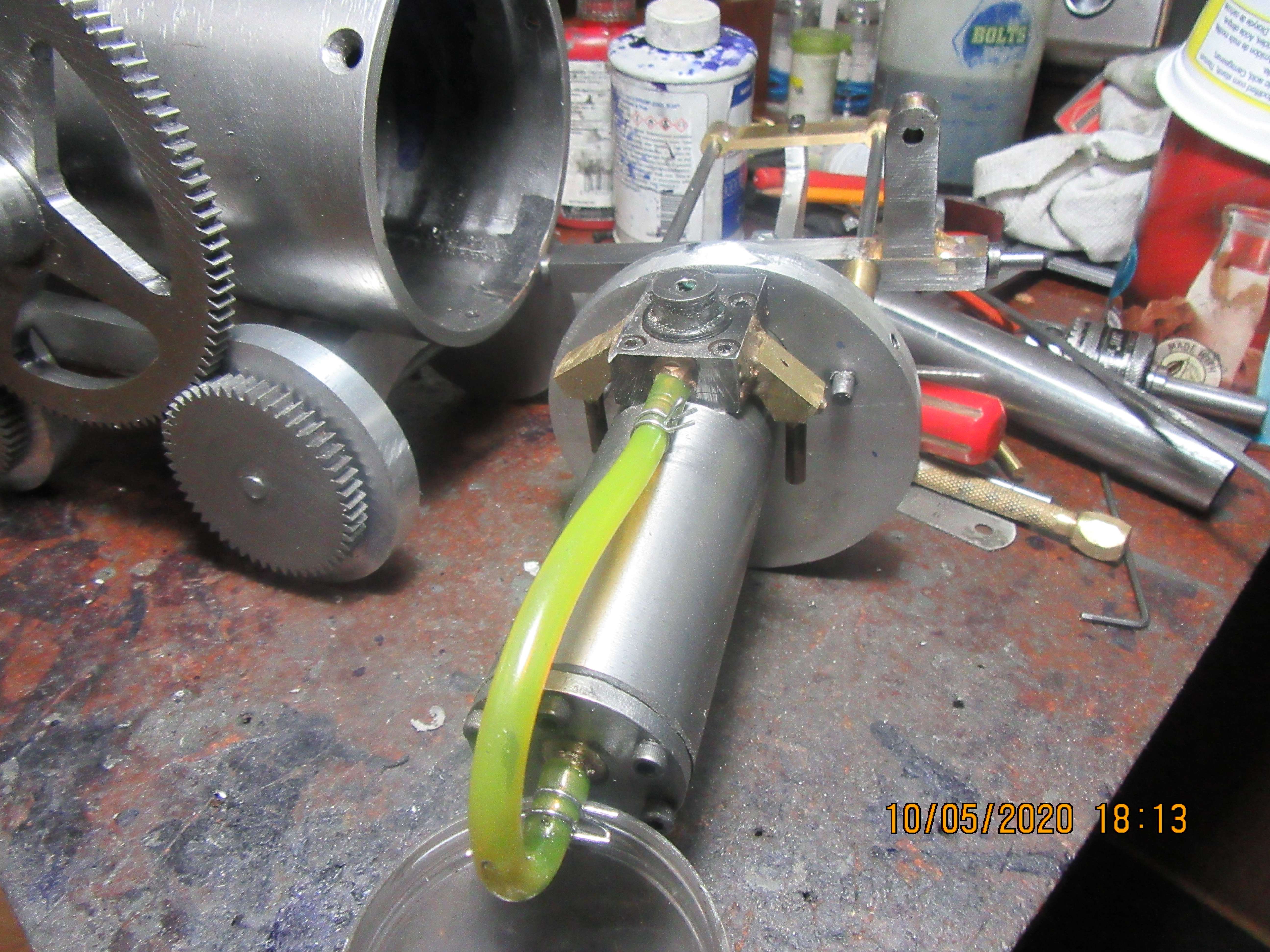
Before I can make any more progress, I have to back up a little and repair a problem. The elbows which feed air to my 4 way rotary valve are interfering with the inside of the "boiler" pipe. I have designed a new "close fit" elbow, and will be machining and installing a couple of them today, so I can start working on the business end of my Trevithick.
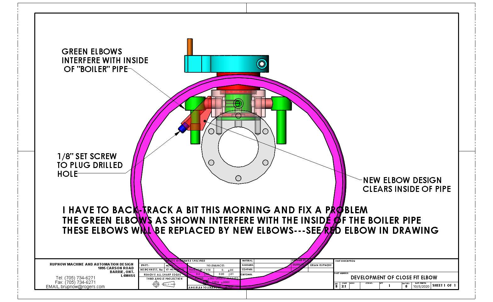
This is the new "clearance style" 90 degree elbows finished. You will notice a small hole in the top of the right hand elbow. I didn't plan that. A dab of J.B. Weld will fix it. Tomorrow, assuming everything fits properly, it's almost time to turn my hand to the mechanism that operates the 4 way valve.