Building of TINY INLINE 4 in Brazil

Home Model Engine Machinist Forum

Help Support Home Model Engine Machinist Forum:

This site may earn a commission from merchant affiliate links, including eBay, Amazon, and others.
As on the previous post I still did not have the videos uploaded on the youtube site, I`m posting some videos of my progress here.

Thirst one is the milling operation of the crankpin using the 4th axis on the milling machine. Observe that the 4 axis were used for this operation
[ame]https://www.youtube.com/watch?v=KrZ3f1csRGc[/ame]

The second one is the grinding of the crankpins on the crankshaft.
As the space was too small, I had to order a spacial Borason grinding wheel with 4mm thickness.
[ame]https://www.youtube.com/watch?v=QC7W0vYCw5U[/ame]

Here you see the center bearings being ground
[ame]https://www.youtube.com/watch?v=HwWJKH-FDT8[/ame]

I will post some more videos this weekend.

Have a good weekend to all.

Edi
 
Hello again!
This weekend I have done a good progress. I have finished the Spar Plugs, the bushings for the connecting rods ans also made the motor mount.

Here are the pictures.

The finished spark plugs


And the videos of the CNC operation of the body
[ame]https://www.youtube.com/watch?v=l3UNLPz9syc[/ame]

Maching the the cinecting rods bushings


Spliting the bushings using a circular saw


In order to get a good adjustment of the bushings to the crankpins, I had to make a device to turn the halves together


Mounted connecting rods. It is running smoothly


Here the oil tube was installed on bottom side of the connecting rods


I was taking a look at the engine plans and decided to make the motor mount.

Squaring the stock


Roughing passes using a milling head


Machining the 20 degrees angle


Parting off. I did a blank long enough for 4 parts


Bringing it to the right width


Finished


Ok, a couple of more parts done.
Almost there!!

Edi
 
Hello guys!
You may observed that the spark plug body was machined on a CNC lathe. Maybe this would’ not be the right thread to talk about that but, once this is associated to this engine building, I will tell you a bit about this machine.

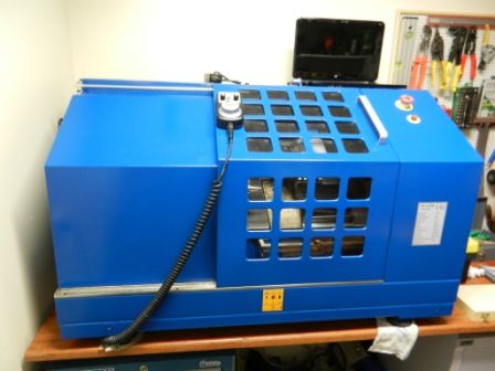
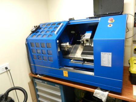
It is a SIEG bench top 8 tool turret slate bed CNC lathe. I have purchased this machine a long time ago but the machine I originally received did not worked. The Sieg company in china tried to fix the lathe from China sending me several versions of the control program. I spent almost 4 months doing what they were asking to do without any progress.
Finally they decided to recall the machine so I returned it to the local Brazilian dealer. After 4 more months they sent me a brand new machine (working machine).
well, this time the machine is running very well, I did several tests on it with very good results.
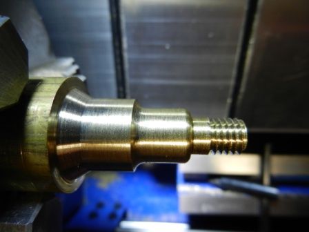
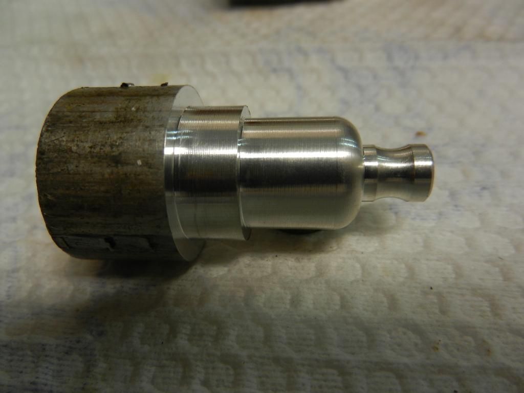
I did some tests to practice my ability to write the G Code program as well as to test the machine.

See sample and videos of the tests bellow.


A couple of pictures of the machine. The black thing sitting on top of the machine is a Lap Top computer that I`m using to control the machine


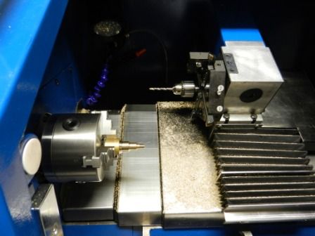
Here you have a better view of the 8 tool turret. It has 4 external and 4 internal tool post


And here a video of one of the tests
[ame]https://www.youtube.com/watch?v=3kMRtjMks9o[/ame]

Based on my experience with this machine so far, I can tell you that I`m happy with it.
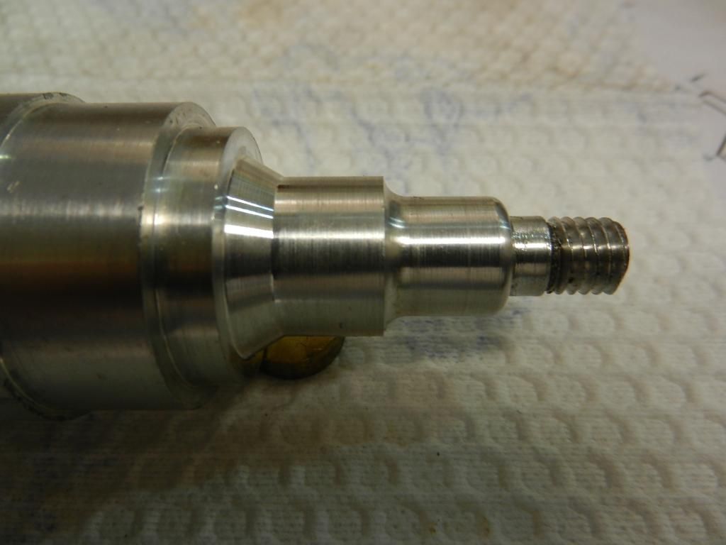
The only part of my current project (Tiny 4 inline) that I have machined on this lathe so far, was the Spark Plug body.

Thanks for following this thread and posting appreciated comments

Edi
 
Loved the thread just got my plans for the engine today

Looking forward to the build after seeing this:)

Mike
 
Hello Guys!
After a long time I was able to do some more work on the Tiny 4 inline project. I have touched the manifold, exhausting and the valves.
Bellow is the intake manifold being machined on the milling machine


Here is the manifold soldered to the carb mount


Bellow is the exhausting mount. Flange and pipes soldered


Now the assembly is polished


I also started to machine the valves. First I tried on the conventional lathe than I thought I could do it on the cnc lathe once it would be a repetitive work.

Here is the first valve on the conventional lathe


This one is the machining of the valves on the cnc lathe


And here the valves semi-finished. I decided to leave some material to finish on the conventional lathe because the tight tolerance on the valve stem and the head hole, also to guarantee the concentricity between the stem and the chamfer.


Today I prepared the camshaft on the lathe. I will post the pictures and video lather.

Thanks.

Edi
 
Hi Edi,
Looking very good :)

Just starting myself,..well still looking at the plans Lol.....Still setting up my CNC lathe and milling machine taking a lot longer than i had thought it would.

Still got to get my head around Mach3 and Cambam.

Do you have any Gcode for this engine? that you wouldn't mind passing on,..I can prove that i have paid for the drawing last week for this engine,

Anyway any help would be great :)

Mike
 
Hello Mike!
I`m happy to know that you have selected the same engine I’m building. It is a intriguing project. Kel the man that designed this engine did a good job on the drawing very detailed, you will not face problems only be prepared to deal with very small parts.
No problems, I will be glad to share the G codes with you but you will need to test it before because there are 3 different G codes (A, B and C) used on the controllers available on the market the one I have uses B.

Good luck with your building. feel free to ask for any help.

Edi
 
Hi Edi,

I'm using Hobbycnc controllers,...don't know if they are a/b/c ? do you know how to find out?

Mike
 
Mike,
First take a look on the Hobbycnc manual and look for a list of the G codes it uses. As I said before (according my limited knowledge) there are 3 types of FANUC commands on the market, type A, B, and C.

Go to the internet and google for a table of G codes types and compare which one maches with the one the Hobbycnc uses. I found in one article that Type C is European standard.
Take a look here, page 16 and 17 https://books.google.com.br/books?i...ble of types of cnc g codes a b and c&f=false

For example: Type A and B uses G70 for finishing cycle and type C uses for the same cycle G72. Thread cycle on Type A is G92 Type b is G78 and Type C is G21.
Another example: Data input in inch on type A is G20 Type B is G20 and Type C is G70.

I had to do that for my CNC lathe from SIEG (Chinese brand) and I found that they use Type B code.

I hope I could help you. There are many fellows here that have a better knowledge on CNC matters than me.

Edi
 
Hi Edi,

Yes i see what you mean now,..I have just looked at Mach3 which is the software that controls my drivers "hobbycnc" and it looks like its type "B".

It looks like if i sit and change the gcode i can use any A B or C as long as they do the same movment.
Do you have a small gcode file there i could try if i can change it than thats fine if not i do not want to waste your time in sending more code to me which i cannot use :)


Mike
 
OK Mike. Don’t worry it is my pleasure to be of any help for you.

I`m sending attached to you the program for the Water Pump Bracket blank profile Drawing Sheet 25 Rev. C.
See bellow the attached file. The file name is in Portuguese, it means `Pump Support Profile.

For your knowledge the dimensions are in millimeters, here in Brazil we use metric system. I could work with inch but I don't feel comfortable with that.

It is not exactly a simple one, however if it pass on your test, the probability of working in a more complex part is really high, than I will send you all the other programs I have.
Oh! I forgot to tell you that I use a Cam software (MasterCam) to generate the G codes. There are many other ones that do the same, you may find one that is suitable for you.

USE A 3mm END MILL ON THE TEST (the program was generated for this end mill). If you don't have metric end mill, no problem you can use 1/8''. The only difference is that the final part will not have the exactly dimensions the drawing calls for because the controller will compensate the radius of the tool as 3mm tool diameter and you are using 3.175mm (1/8'').

Please let me know if you need more help.

Good luck

Edi

View attachment SUPORTE DA BOMBA CONTORNO.doc
 
Hi Mike!
I forgot to tell you that the X and Y axis zero is the first top small hole on the right side of the part. The Y zero is the top of the blank.
The Z depth is programmed for 1,7mm. I suggest you to use a piece of wood with a thickness of over 2mm so the part will not fall out when finished the operation.


Edi
 
Hi Edi,

Thanks for the Gcode,...wont have a chance to look at it as i'm working away from home till the weekend

Mke
 

Latest posts

Back
Top