
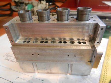
Building of TINY INLINE 4 in Brazil
- Thread starter e.picler
- Start date


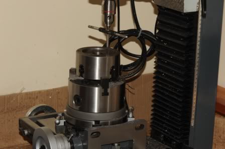
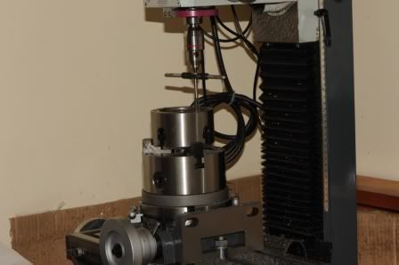
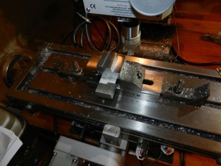
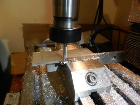
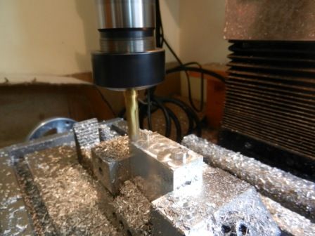
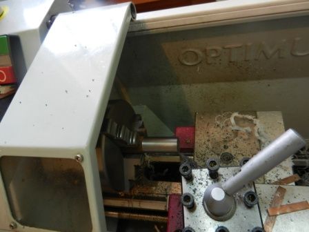
Can i ask what mill you use, it seems its Optimum?
Hello Hacklordsniper!
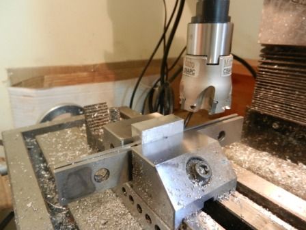
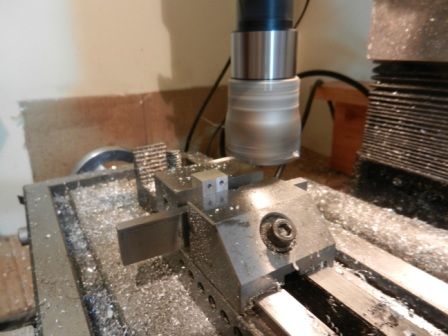
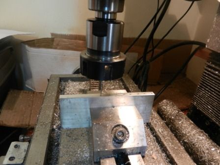
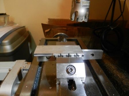
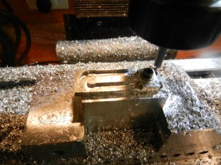
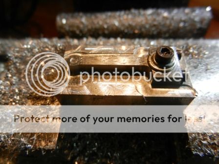
Yws it is Optimum machine. I purchased two machine from them last year, one D180 Vario Lathe and one BF20 Milling Machine with some acessories.
This year I purchased the CNC kit for the milling machine.
Do you need some specific information?
Thanks,
Edimilson
Hello, we have identical machines. Im quite happy with my mill BF20L but quite unhappy with the D180 Vario as it came with quite many manufacturing defects. How happy are you with yours?


Enter your email address to join:
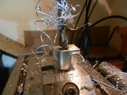
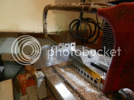
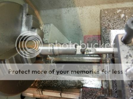
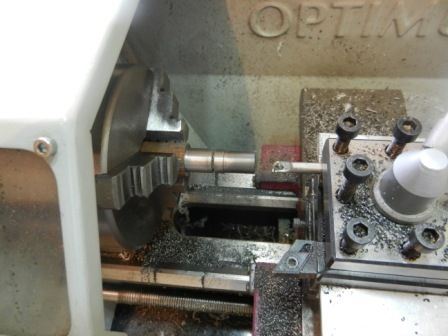
") That lathe set up looked very hairy, looks like the machine would have started bouncing.
That lathe set up looked very hairy, looks like the machine would have started bouncing.