Building Jerry's Donkey

Home Model Engine Machinist Forum

Help Support Home Model Engine Machinist Forum:

This site may earn a commission from merchant affiliate links, including eBay, Amazon, and others.
Nicely done Jerry! I especially appreciate your attention to the finer details. The models I find most attractive are the ones that are in fact built, not as stand-off scale, but ones that possess at the very least, true representations of the part or parts involved. On such a project as this one, the more detail you can put into it the better and boy have you done a terrific job so far. :bow: Of course all of these finer things takes a lot more time obviously, both in the thought process as well as the making of the pieces themselves. The final result .... a masterpiece such a this one. Tally Ho!

BC1
Jim
 
Jerry: Have enjoyed watching your progress. What a great build. Between the pictures and your narrative I feel like I'm a part of your project. Thank for taking the time to share your knowledge. Roger
 
I haven't posted much on this for quite a while but I have been working on it. The problem is that the progress has been difficult. Lots of effort, little success. Not spectacular failures that you might enjoy. Just disappointing results. The problem is scale. At a scale of 12:1 there are some things that can't be done without the skills of a watchmaker but still need to be represented in some way.

In their brochure, they specifically mention that steam and exhaust piping to the steam chest uses bolted flanges so that is what I have been wrestling with. Both steam inlet and exhaust flanges are on top of the cylinder and the exhaust piping leads up into the funnel where it aids draft and takes the steam away from the operator. The steam piping passes through a control valve and then branches to the two cylinders in an unusual 3 way elbow. Here is a cut from the brochure:

amhoistvakve.jpg


From the day I started this project, I have dreaded the day that I had to deal with this elbow and the valve. The valve has a very long stem (about 4' that has two handles that are convenient to the operators location. The branching 3 way elbow below the valve is unique. No such thing from PM Research and not easily found in full size either. And at 12:1 scale, these things are very small. My usual approach to things like this is to ignore them until a solution pops out of thin air.

Today, under pressure, a solution appeared. I decided to make the valve and the three way elbow as a single piece. This is a departure from the original design but it keeps the flavor of the original (SORT OF). I have convinced myself that if I had been there as a consultant on the original design, it might have been done this way.

donkeyvalve004.jpg


The bottom end of the control valve is ball shaped and the lines to the individual cylinders branch from there. I have decided to bend the steam pipes instead of using elbows. The flow should be better. All piping connections at the cylinder use flanges and ferules as per AmHoist specs.

Much more to work out In this piping. I don't want to use anything smaller than #2-56tpi and SHCS will be used until all other assembly details have been worked out, just for convenience. If I ever get to a point of completion, one of the final steps will be changing to studs and nuts.

Thanks for watching.

Jerry
 

It looks really good Jerry.

I am sure the original designers would be proud. You should be too.

Keep at 'er!
 
The flanges and pipe bends really clean up the look. They were probably easier too.
Alan
 
Surprised you went through all the worry about the look of flanges and then just opted for bent pipes, to me the cast pipe fittings are more a feature of American steam than flanges. Its also quite easy to solder a socket to the side of an elbow to make the 3-way.

Just for an idea of scale what size pipes are you using for supply and exhaust?

Hard to tell from the old illustration but did the end of the valve have a support from the boiler stay, this would have saved excess strain on teh valve and spindle.

J
 
Thank you Kevin and Miner49er for the kind comments, and thanks for leaving a note that shows you are watching.

Thanks Jason for the critical comment. This forum needs a little more of that. It is easy to say "nice job" and much harder to say "think again". So I thought about it. My solution wasn't all that great. My next one may not be either.

I got into this situation by lack of experience and lack of forethought and choice of a scale (1:12) that makes some of the finer points of the model very difficult to reproduce. I started with the larger parts of the project when I should have given more thought to the smallest. If I had chosen a larger scale, I wouldn't have this problem.

Pipe size:

Jerrysdonkey2016.jpg


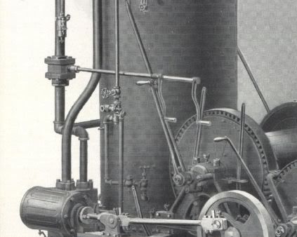
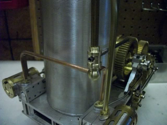
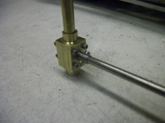
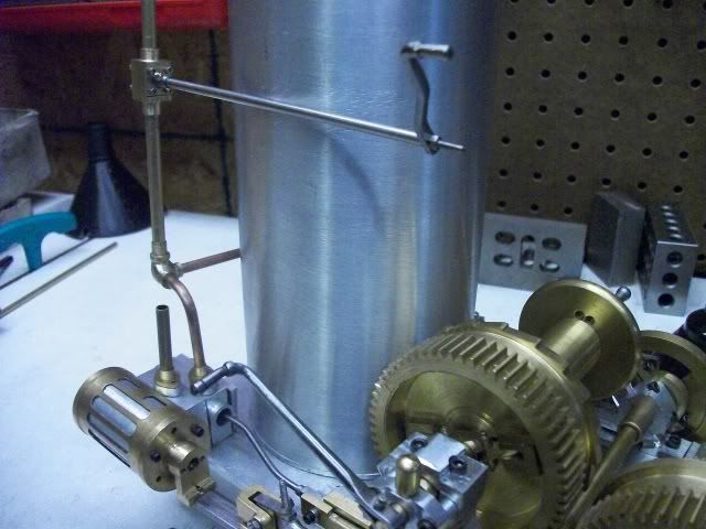
This is the steam pipe on the port side. I measure it at 2" OD which at 1/12 scale equals 1.67" so I will use 5/32" tube for air in and 3/16" for exhaust. I might have been better of to choose 3/16" inlet and 1/4" exhaust. Then I could use the PM research cast elbows, but for some reason they just look too big to me.

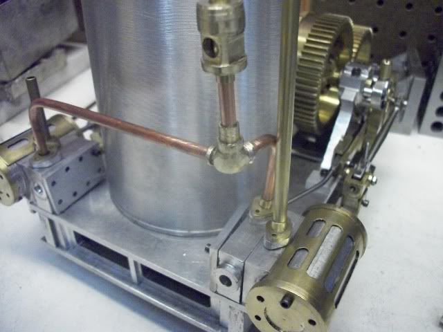
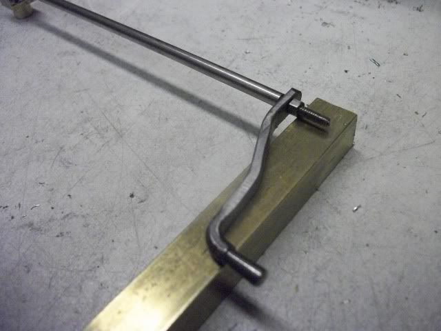
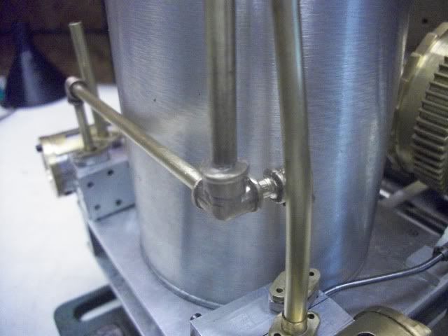
Can I do any better? Probably not but I tried. Here is the results of a lot of filing on a three way elbow. Does this look better?

threewayelbow005.jpg


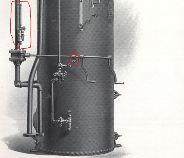
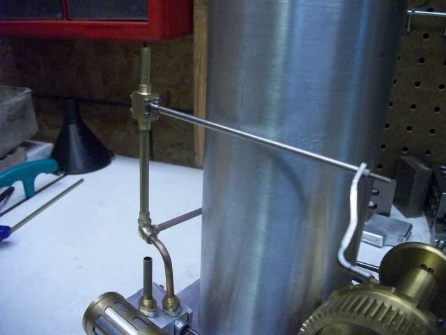
Here is another cut from the brochure. It seems to show that there is a bracket of some kind that supports the shaft of the steam control on the boiler stay. I circled it in red for emphasis. The other item that is circled in red on the steam pipe above the control valve is a mystery to me. What is it?

Amhoistvalvehanger.jpg


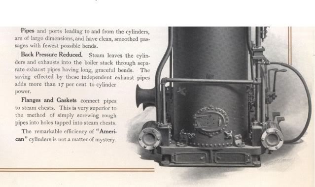
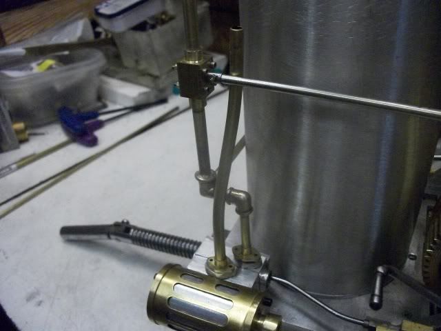
While taking a look at the brochure, it is clear that "truth in advertising" was not all that important at the time. Do the gentle bends of the exhaust pipe really add 17% to the power? At the top of those pipes with the gentle bends is a 90° elbow. Does that help or hurt?

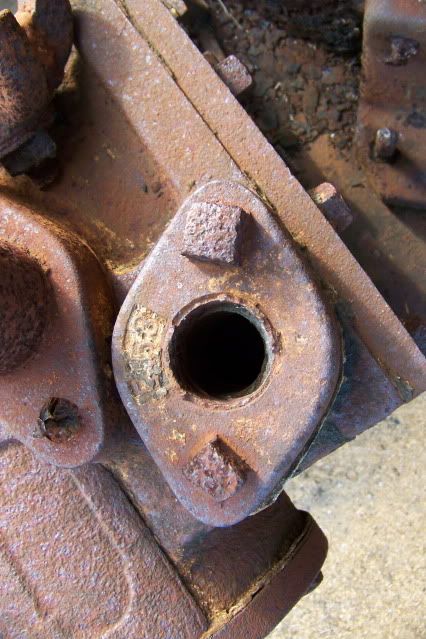
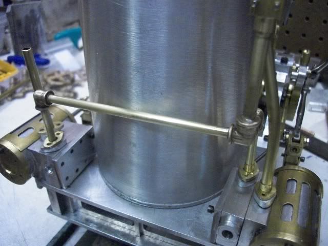
The next paragraph shows how important AMHOISt thought the flanges were. I couldn't think of any other way to make it work. The piping can be assembled and then bolted to the cylinders.

Amhoistpiping.jpg


I am still undecided on this.

Jerry
 
Hi Jerry,
I would say that the device you have circled is a lubricator.
gbritnell
 
3-way looks a lot better. Agree it may not seem nice to say it sometimes but there are a lot that just like to say nice job but a bit of constructive critisisum should not go amis now and then.

I also think that it is a displacement lubricator, condensate would form in it, sink to the botton and displace the oil which overflowed (being lighter than water) and was drawn into the steam pipe.

That bracket on the valve rod looks like it joined onto the diagonal boiler stay that is shown of the drawing you posted yesterday just behind the clutch handle so looks like you will have to add the stays.

The other way to avoid having to unscrew the pipework is to use unions which I mentioned in Brians build.
 
Jerry,
My read on the exhaust paragraph says two things...
a) The gentle bends reduce back pressure... I would agree but it is a minimal reduction
b) The separate exhaust pipes increase power by 17%... That's dual pipes as opposed to teeing both cylinders into on pipe. An engine is an air pump. The more you can do to help it breath the more efficient it is.
Alan
 
I ordered some elbows. We'll see what it looks like.

Today's effort was the control valve. A simple project except for the size. The valve body is a 3/8" brass cube with spigots for pipe connection top and bottom. The valve spool is 1/4" polished shaft steel with a 1/8" through hole and a 5/32" sticky out part for the control shaft. The sticky out part is drilled 1/8" for the shaft with a 1/16" cross drilled hole for a pin. A 1/16" thick cover is held on with 4 #0-80 SHCS and nuts. It is simple and seems to be air tight and smooth operating, on/off in a 90° turn. There is room for some packing if it is needed.

Controlvalvewhandle016.jpg


The shaft is a piece of 1/8" stainless and the control handle is a piece of 1/8" CRS with a turned handle. The rest of the the shaft was then hammered to a square cross section and tapered before being finished with files and bent to shape.

Controlvalvewhandle019.jpg


Now I have to decide on the correct relation of this handle to the valve. Usually a handle is lined up with the valve, but I am not sure that is how I would want it if I was the operator. Straight down would be full on and off would be sticking out horizontally at the 9 o'clock position. I think, that if I were the operator, I would want to pull down to throttle up, so I would put the handle up between 10 o'clock and 11'oclock for full off, like this:

Controlvalvewhandle015.jpg


and pull down to between 7 o'clock and 8 o'clock for full speed, like this:

Controlvalvewhandle012.jpg


The control shaft is at about the operator's shoulder height. This is adjustable with a grub screw on the prototype but I am going to have to cross pin the handle to make it secure so I have to decide. If there are thoughts or opinions or personal knowledge, please post it. I am really undecided on this.

Thanks for watching.

Jerry
 
Jerry,

For operating handles on machinery, they usually revert to off under adverse conditions.

So in fact, if gravity took over, or someone was to fall whilst still holding the handle, then going down would be the safe way to to turn the pressure off.

To turn something on should always be more difficult than turning it off, hence larger red buttons on control boxes etc. So in your case, using safety logic, going up would be used to turn pressure on.

But on the other hand, it all depends who made the original engine, he might not have had safety in mind, just ease of operation, in which case, your method would be correct.


John
 
I'm inclined to agree with John that the handles would ideally have a dead man action if they were down for off, looking at the illustrations you posted on the previous page that also seems to show them vertically down. Worth looking on the net for some old photos of donkeys in steam to see if any info can be gotten.

Nice bit of forging on the handle.

J
 
Bogstandard said:
So in fact, if gravity took over, or someone was to fall whilst still holding the handle, then going down would be the safe way to to turn the pressure off.

To turn something on should always be more difficult than turning it off, hence larger red buttons on control boxes etc. So in your case, using safety logic, going up would be used to turn pressure on.

John

Spot on Bogs with one notable important exception........"Boiler Gauge Glass Cocks for the steam and water connections." They are designed open in the down position so that they can't vibrate shut. The drain valve is down for shut, again so it can't vibrate open.

Best Regards
Bob

 
Thanks for the details on making the handle, nice to see how it is done.

Jan
 
John, Jason, Bob,

Thanks for the input. The consensus is clearly down for off. It is hard to disagree from a safety standpoint in today's environment. It is also hard to imagine a machine like this, with all of the open, unguarded mechanism and pinch points being allowed anywhere in today's environment. I guess I will go with that because that is what people would expect to see.

Thanks for the pictures, John. I really enjoy these and the skill of the illustrators of the time is amazing. They reveal a lot of interesting information. It is too bad that there is no detailed design information to go along with them. The differences in the two pictures is worth noting. In the top illustration, it appears that the normal operator's position is toward the rear of the machine. The brake pedal is just in front of the cylinder head, the throttle lever is moved back and the clutch lever pulls to the rear.

On the second illustration, the brake pedal is at the front, as is the throttle lever and the clutch lever pulls forward. They are clearly used in different applications. It would be great to know why the difference.

Jan and Jason -- Thanks for noticing the forged handles. Hammer and anvil work is a nice diversion from the usual stuff. You will notice that I only show one throttle handle even though there will be two on the model. Getting the second one to match the first one will be a challenge. I will probably end up making several and choosing the best match.

Thanks for the input.

Jerry

 
Here it is with cast fitting from PMR. Yeah, I think it is better. Thanks, Jason, for the tip on making the 3-way elbow.

throttlrrbrt005.jpg


throttlrrbrt006.jpg


throttlrrbrt007.jpg


It will look much better than bent pipe at the top of the fake boiler, where there is a concentration of fittings.

Jerry
 
Back
Top