Building a model Drag Saw

Home Model Engine Machinist Forum

Help Support Home Model Engine Machinist Forum:

This site may earn a commission from merchant affiliate links, including eBay, Amazon, and others.
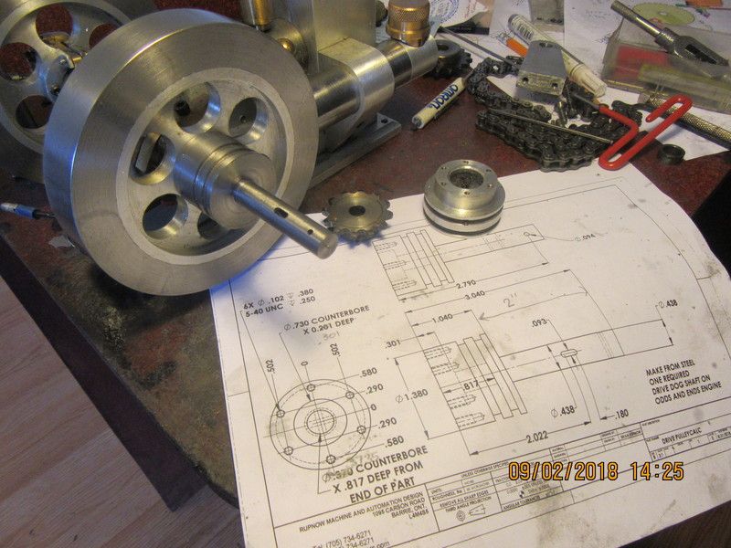
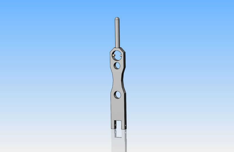
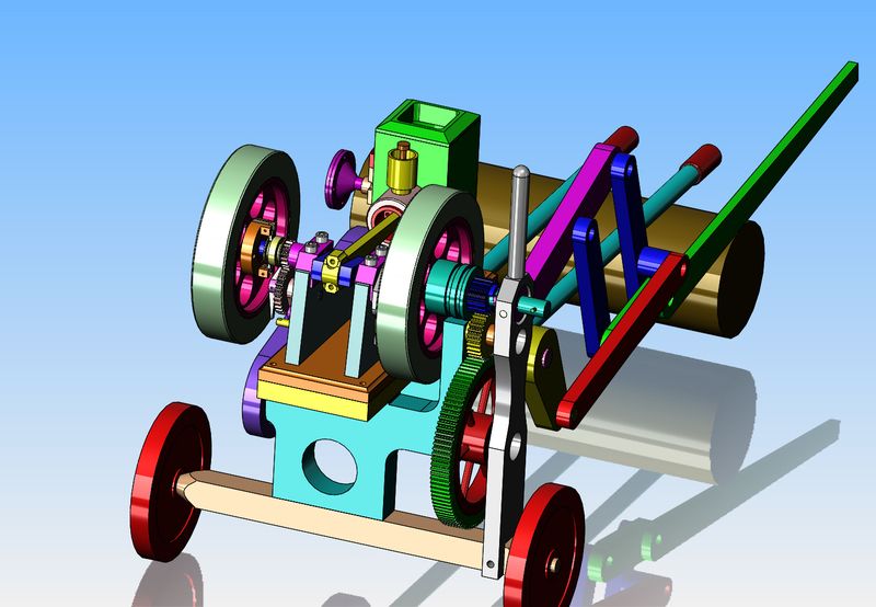
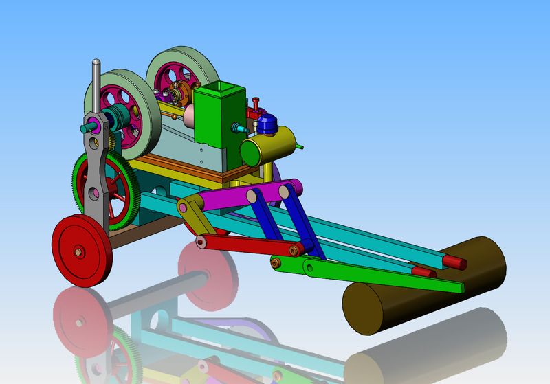
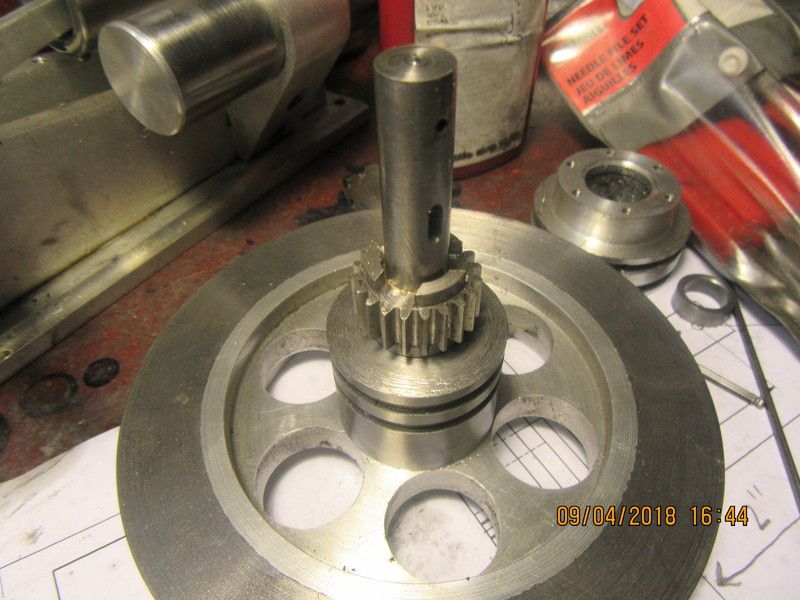
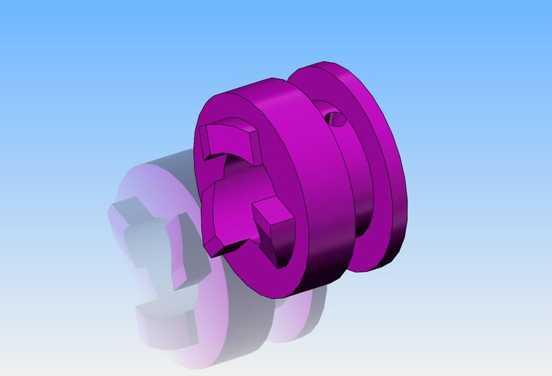
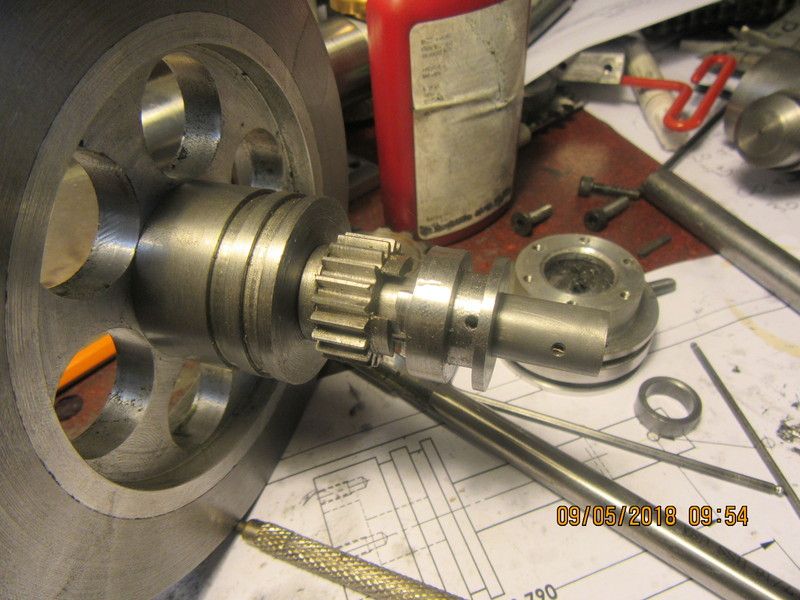
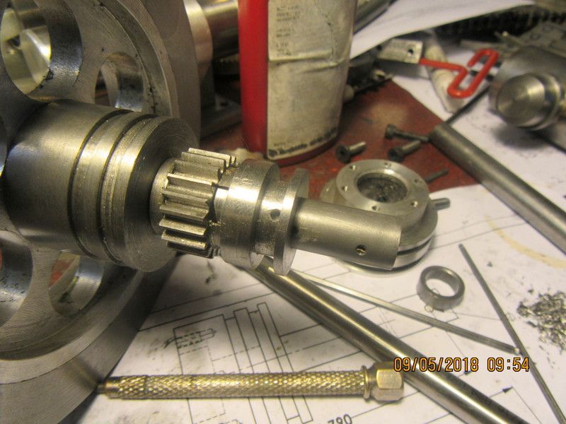
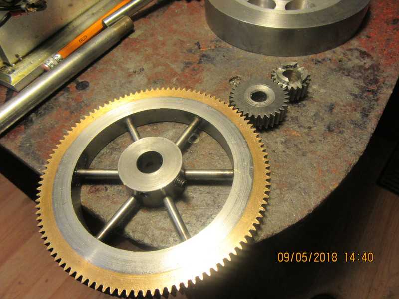
Today I machined the crankshaft extension for the Odds and Ends engine. There is more to this extension than meets the eye. It has two counterbores machined on the far end, one to precisely fit the flywheel hub, and one to match the 1/2" length of crankshaft that extended past the flywheel hub. The end you can't see is drilled and tapped six places to match the clearance holes in the flywheel. You can see that in the pulley I removed in order to fit the extension on. In a perfect world, there will be no wobble in the end of that shaft extension when the engine is running. The 20 tooth gear, bushing, and drive dog will all be fitted to this extension. I machined two grooves in the large outside diameter of the extension in case I want at some point to drive o-ring drive belts with this engine.
qaqKVO.jpg
 
Today has been mostly cad work, figuring out the overall layout, how part A connects to point B, etcetera. I still have to find room for a gas tank, as the one currently on the Odds and Ends engine will be in the way. I'm liking this. The log being sawed is 3" diameter.
aEWFSk.jpg

X3d9Xk.jpg
 
This shows the dog clutch lever by itself and how it assembles to the drag saw, where it pivots on the axle. It moves very little to engage or disengage the dog clutch. Right now I'm not sure how to make it stay "in gear" or "disengaged". There isnt enough movement to use ball detents`. Maybe a couple of spring washers and a bolt through the bottom pivot?
ASjkT0.jpg

GC0XT6.jpg
 
This morning I even found room for a gas tank. I also changed the two members that reach from the engine up to the log. I originally had them as 1/2" round rod, but all of the drag saw videos show them as being rectangular wood. I'm getting close to the point where I start cutting metal.
ZY5PYE.jpg
 
Something in my black old heart tells me that both parts of the dog clutch should be hardened, then "drawn back" to a point where they are tough but not brittle. My heat treat capabilities are limited to oxy-acetylene torch and my wifes kitchen oven. I already had the gear, made from 1018 mild steel so can't heat treat it, but I am going to machine the drive dog tomorrow, and it just happens that I do have a piece of o1 material the right diameter. I will machine it to size, heat it to cherry red with my torch, then drop it into a container of oil. Then 2 hours in my good wifes kitchen oven at 350 degrees F for two hours.
kyFCJw.jpg
 
All the gears that will be used in the drag-saw are finished. The largest and smallest were "repurposed" from the walking beam project. The center gear was just finished 15 minutes ago, and I'm done for the day. My back is killing me and I have to go across town and pick up some aluminum from my supplier.
VzvXbk.jpg
 
Brian, I think a back massage should be the order of the day! I love your way of working through problems.
 
So far today, it has been "work like Hell and not accomplish much" kind of a day. I did drill and ream holes in a piece of scrap at the calculated gear centers, and all seems to be fine. Gears mesh with no binding. In the picture they are running in the mill with lots of oil on them. I will let them run for 15 minutes or so before tearing the set-up down. Now, I have a calculated number for the sprocket centers, and will test the chain and sprockets the same way, after I have shortened the chain to the appropriate number of links.
aOPjCu.jpg
 
My calculation for sprocket center distance seems to have been "right on". After a half hour struggle with the master link it all goes together and looks about right. Not under tension but not a lot of slack either. The uglies on the face of that large sprocket are a testament to just how bad my vision is getting for welding things. A little J.B. Weld will fill those cavities. I buy my sprockets as "flat" sprockets with no center hub. I make up my own center hubs and weld them in.
W1gj7f.jpg
 
Brian, you are welcome. I watch all of your builds, have even built one of your beam engines. Thanks for the learning experiences. DW
 
Hello Nelson--Good to have you following. Werowance--That large gear with the spokes wasn't difficult to make, it was just time consuming.--Brian
 
Progress is being made. This morning I finished the 1/2" thick engine sub-base which connects the engine to the rest of the components underneath, and gives me an alternate place to mount a gas tank. The original gas tank on this engine was mounted to the side where you see the two socket head cap screws, and would have been in the way. The next plate I make, which is going to provide a place for the 108 tooth gear shaft and the 30 tooth gear is going to be a challenge.
iFiSe4.jpg

1ZqdOK.jpg
 
The complex endplate is roughed in using the bandsaw, and tomorrow will be milled to finished size. That 1 1/2" hole bored in the center is cosmetic, nothing more. The large sprocket with the shabby welding showing on the one face was treated to some J.B. weld, left overnight to harden up, then painted with a rattle can. A little paint hides a lot of sin!!
RbIEmQ.jpg

yysiXF.jpg
 
Brian
My brain is going faster than you can machine. Question: How are you going to connect the saw to the drive with the engagement lever where it is? I've always liked the drag saw and yours is looking to take shape.
Enjoying it all.
Nelson
 
Back
Top