Building a model Drag Saw

Home Model Engine Machinist Forum

Help Support Home Model Engine Machinist Forum:

This site may earn a commission from merchant affiliate links, including eBay, Amazon, and others.

Brian Rupnow

Design Engineer
Project of the Month Winner
Joined
May 23, 2008
Messages
14,974
Reaction score
8,265
Location
Barrie, Ontario, Canada
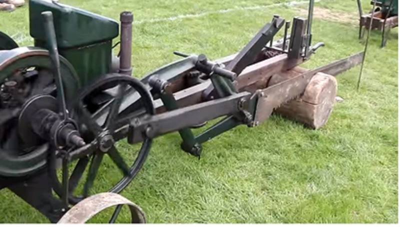
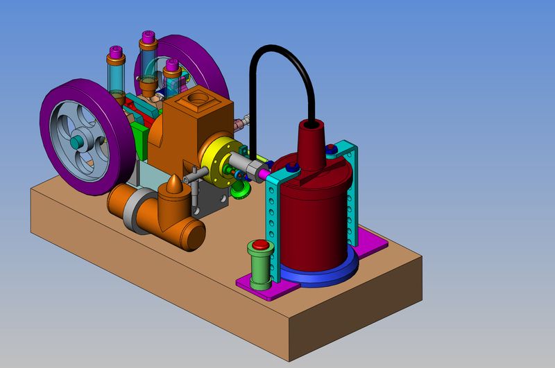
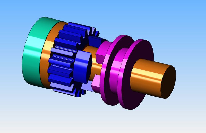
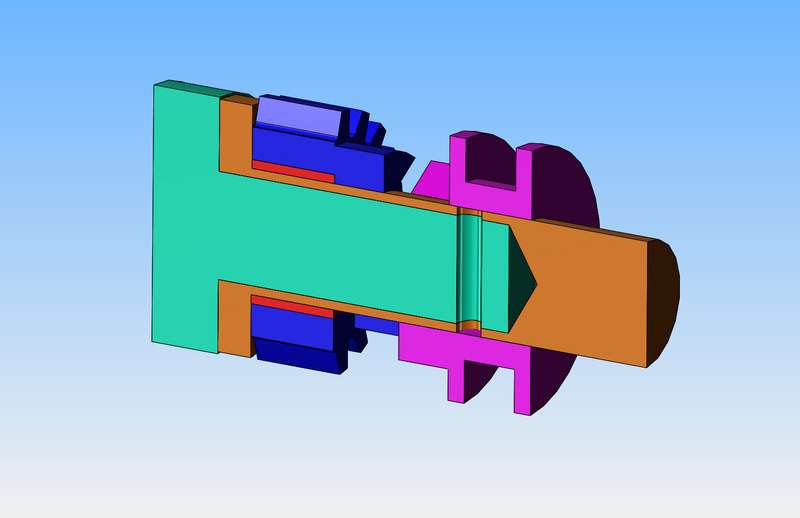
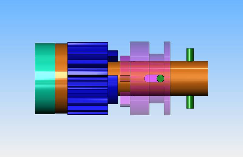
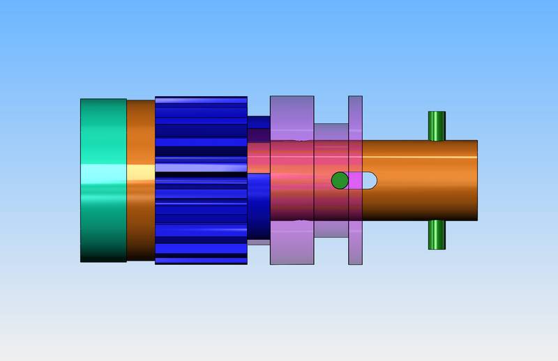
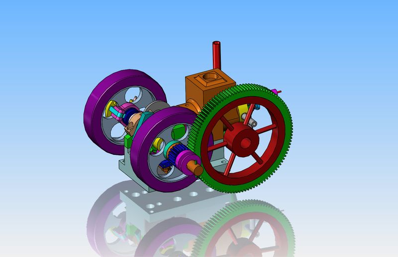
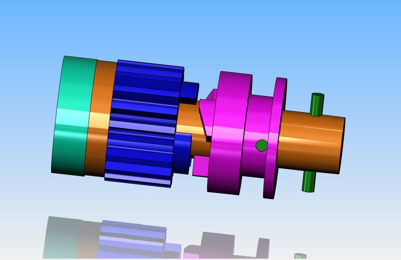
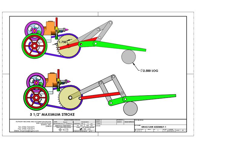
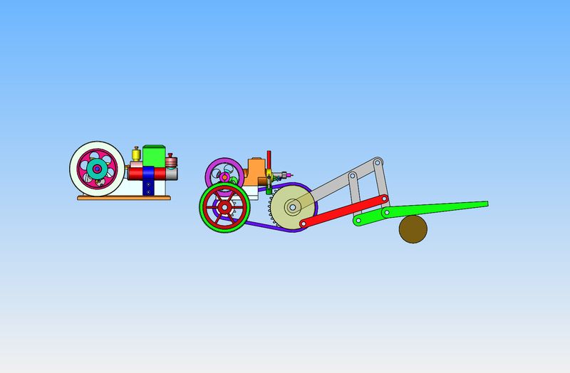
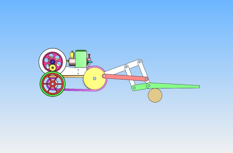
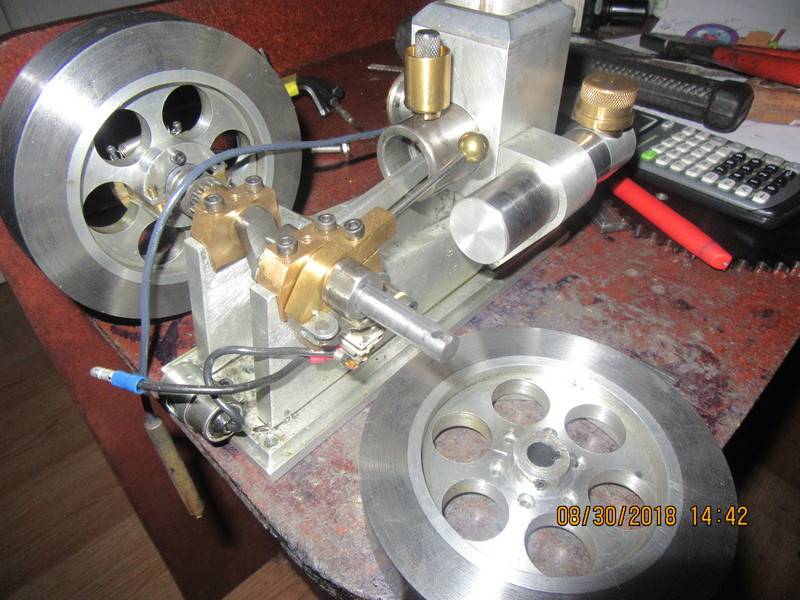
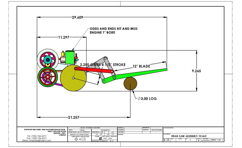
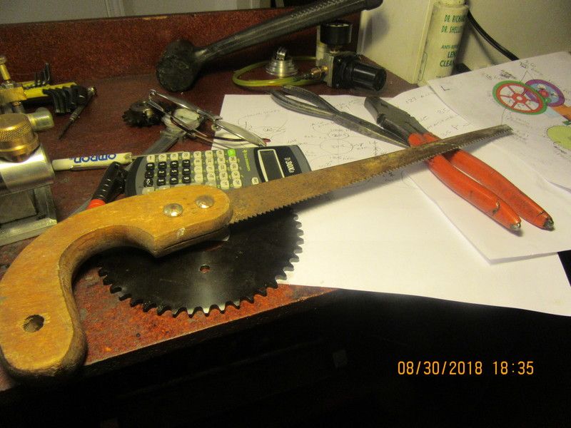
I am going to build a model drag saw. The power for this saw will come from the second i.c. engine I ever built--The Kerzel hit and miss engine. There are so many things that I don't know about a drag saw that it makes my head vibrate, but I am a fast learner. I am going to use a driving mechanism similar to the one in the attached picture. One of the first things I have to design is a "dog clutch" which enables me to shift a lever and put the engine "out of gear" so that I don't have to shut the engine down to stop the saw blade moving. I have at one time or other built everything in a drag saw (on other machinery) except for a dog clutch. Since I have the capability to cut my own gears, this saw will have a gear drive instead of a sprocket and chain. If you like this sort of thing, then follow along. Parts of this story may be boring, but parts of it will be something new.
8wd8Ep.jpg

WQkuN6.jpg
 
This first bit is a head scratcher. Where do I start?--well, the green colored part is the available shaft end and flywheel hub on the side of the Kerzel opposite from the governor weights. It is 3/8" diameter x 1.125" long. The brown colored part is a steel shaft extender 3/8" i.d. x 7/16" o.d. that slides over the Kerzel shaft and is pinned there by a 3/32" diameter cross pin. (And maybe some Loctite). The dark blue gear is a 24 dp x 20 tooth gear which has an internal bore of 1/2" and has a bronze bushing (red color) pressed into it. It also has three "dogs" machined on one side. It actually "floats" on the shaft extender and is not keyed to it in any way. There is a shoulder on the end of the brown shaft extender which the gear rides up against. The pink part is a steel sliding bushing with three "dogs" machined on it that will fit into the three slots between the dogs on the blue gear. It has a "groove" machined into the outer diameter, which a pair of pins on the shift lever fit into. It is capable of sliding along the shaft extender, and is also keyed to the shaft extender so it can not rotate freely. (I haven't quite worked that last bit out yet.)
kz2xrr.jpg

Z1NDt5.jpg
 
Okay---I got it!! Two pictures here, one with dog clutch engaged and one with dog clutch disengaged. The green cross-pin on the extreme right hand end is for my electric starter.
1YfMgh.jpg

rHunxg.jpg
 
I may very well put a ramp on the driving dogs. I just did a little test out in my main garage. I put a spruce 2 x 4 in my vice and got one of my handsaws. My son was here and had a stop watch built into his cell phone. I sawed at what seemed to me to be a reasonable speed, and he timed me for three different 10 second intervals. Seems like 14 strokes per 10 seconds is "reasonable". Six times 14 equals 84 strokes per minute. The ratio between my two gears is 108 divided by 20 equals a ratio of 5.4 to 1 So---5.4 x 84=453 rpm at the engine crankshaft. I don't remember what speed my Kerzel engine runs at, but I will probably start it tomorrow and check it with a laser tachometer. I know my single cylinder flathead engine runs at about 1000 rpm. I think the Kerzel runs slower than the flathead, but I will have to check it and see. If I have to have a second stage gear reduction built into this drag saw to make it work, I would much rather know now at the design stage than after it is all finished.
 
First thing to do this morning was machine ramps on the driving dogs. Others have told me this makes the dog clutch much easier to engage. Now I'm off to my garage to start the Kerzel engine and decide what rpm it runs at.
k8CjJU.jpg
 
so how will the clutch engage/disengage while running? some sort of lever mechanisim running int he grove on the purple piece? or some sort of spring loaded setup? I'm just not understanding the mechanics of that part. at least not the ability to do it while running.
 
I set up the Kerzel engine this morning and ran it. My laser tachometer tells me it is turning at 960 rpm. This is twice as fast as I require, in order to get the saw to make 12 to 14 strokes every 10 seconds. I can not make the engine run any slower, so I will have to put one more set of gears in the drag-saw gear train. I currently have a 5.4:1 ratio in the gears on the saw, so I will have to install a second set of gears at 2:1 ratio to give an engine speed of about 900 rpm.
 
the square dog clutch ,under load is Very difficult to disengage. I have made then with a 1 degree taper to assist with Dis-engagement. on the last one I used, the motive power was 15 Kw and 50 RPM
 
Following your build Brian. As usual, you have some great ideas here. Even though the load on a model may not be that heavy, you may find that a single pin on your sliding clutch is inadequate. Splines can be a pain, but that may be required to ensure that you don’t sheer off your pin during engagement from a standstill.

Looking forward to seeing it in action!

John W
Camp Verde, AZ
 
I've spent 6 hours today in "geometry world", coming up with a set of linkages that will work for the drag saw. I know of no set of equations that will let you calculate this stuff. It is more "try it and see" engineering. What I have here is a set of linkages that go through all of the required motions without binding or going into a "lock" position. Now I have to take the time to do a visual comparison between what I have and what a real drag-saw looks like. This is fun stuff, but it isn't easy. Before I cut any metal, I will build these linkages full scale in cardboard and using "stick pins" work it through all of the required motions.
Z7OAvc.jpg
 
I am having second thoughts about using the Kerzel engine with the drag saw. The Kerzel has a 3/4" bore, while the Odds and Ends engine has a 1" bore, larger flywheels, and is all around a bigger engine. I'm looking at the size of the Kerzel compared to the larger Odds and Ends hit and miss engine and I think the Odds and Ends engine would be a better choice.
YiN5vU.jpg
 
Last edited:
ok, I get it, like a clutch fork on a throw out bearing. now I'm jumping way ahead and wondering what the saw blade will be made out of, I realize a lot of linkages and ratios to work out before you get to that point but just curious.
 
Okay--Got that sorted. The engine is now the Philip Duclos "Odds and Ends" hit and miss engine. In order to get from 1000 rpm at the crankshaft to 84 rpm at the disc which the saw arm attaches, and to fit the constraints of what I have, there are actually two gear reductions coming off the engine shaft and one roller chain reduction. Part of the reason there are two gear reductions is to get the disc spinning the same clockwise rotation of the engine, and to get that large 108 tooth pulley with the spokes far enough away from the engine crankshaft to enable getting a cross shaft underneath the engine to reach the far side of the engine where the chain and sprockets will be. I haven't changed anything on the drive disc and linkages which are shown.
wVooBx.jpg
 
I pulled the flywheel off of the starter side of the Odds and Ends hit and miss engine. It appears that I will be able to make my dog clutch work on this side and still be able to use my electric drill starter. I am proceeding with more layout work on the drag saw mechanism and frame.
hKctTk.jpg
 
This thing is going to be big!! I'm pretty sure I have all the calculations right. The log is 3" diameter which is fairly close "scale-wise". The keyhole saw I inherited from my father and haven't used in 20 years is going to provide the blade for this beast.
5aUmVq.jpg

lWisj8.jpg
 
Someone said that a journey of 1000 miles begins with one step. The only thing on this drag saw that I haven't made before is the "dog clutch". So---that is where I will begin. The design is going to be marginally different from the one in the attached 3D model because of minor differences in the output shaft on the Odds and Ends engine from the Kerzel.
k8CjJU.jpg
 
Back
Top