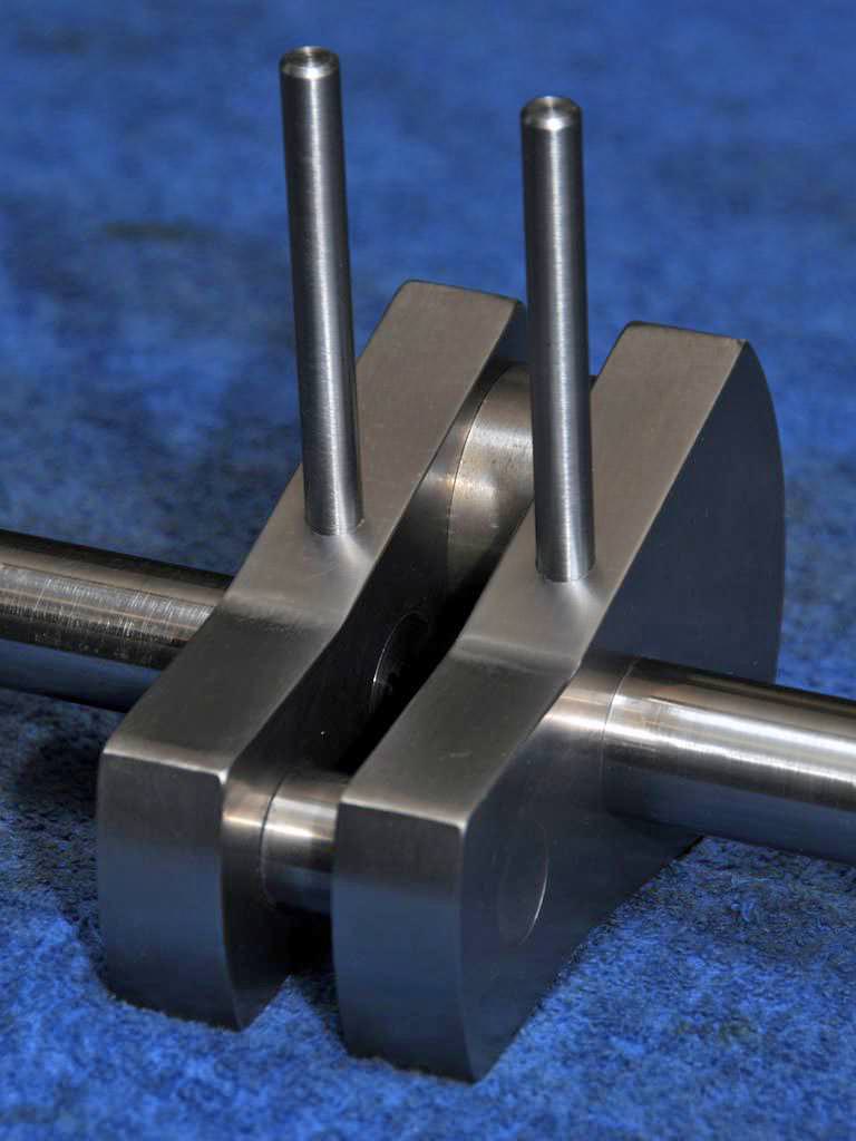
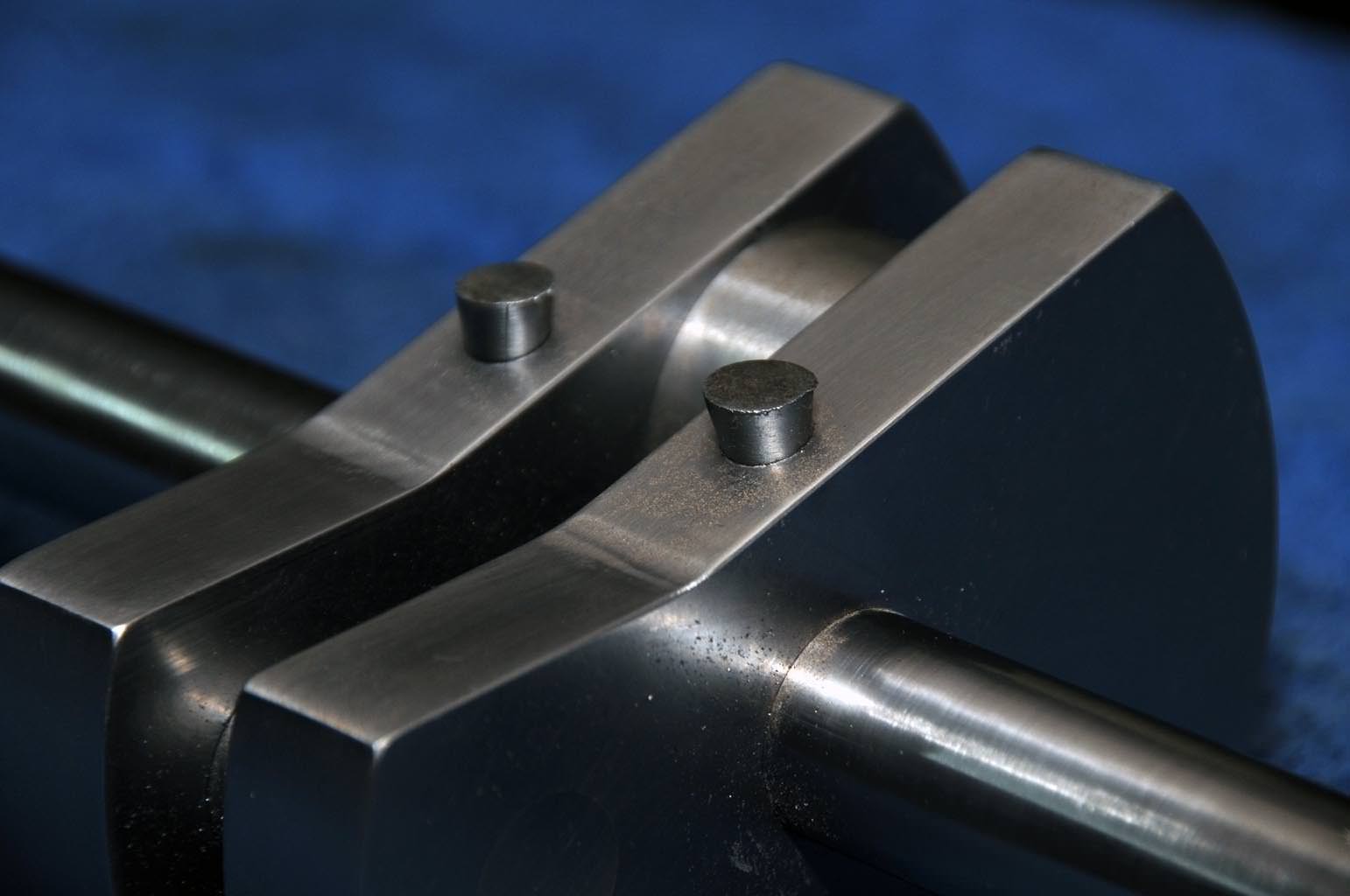
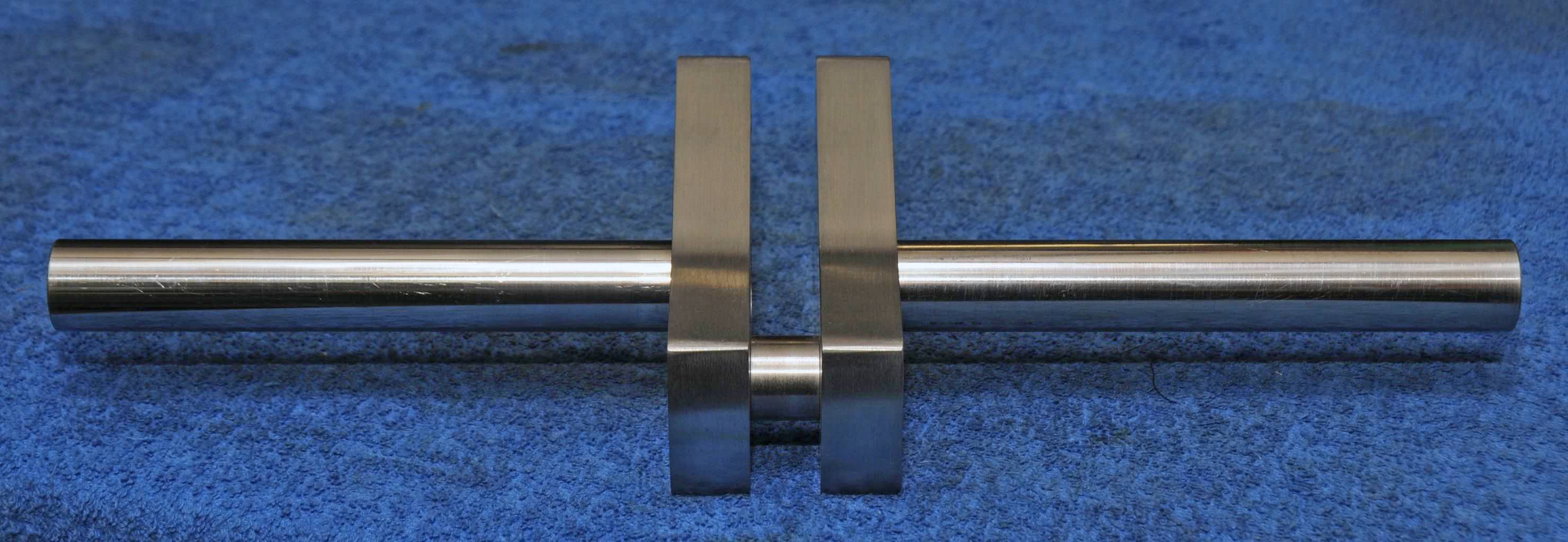
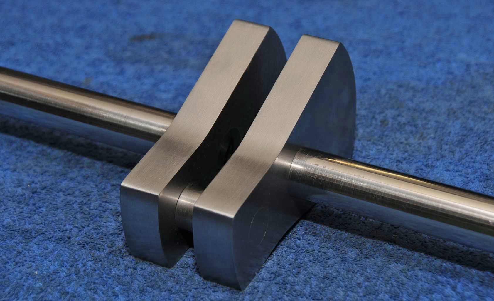
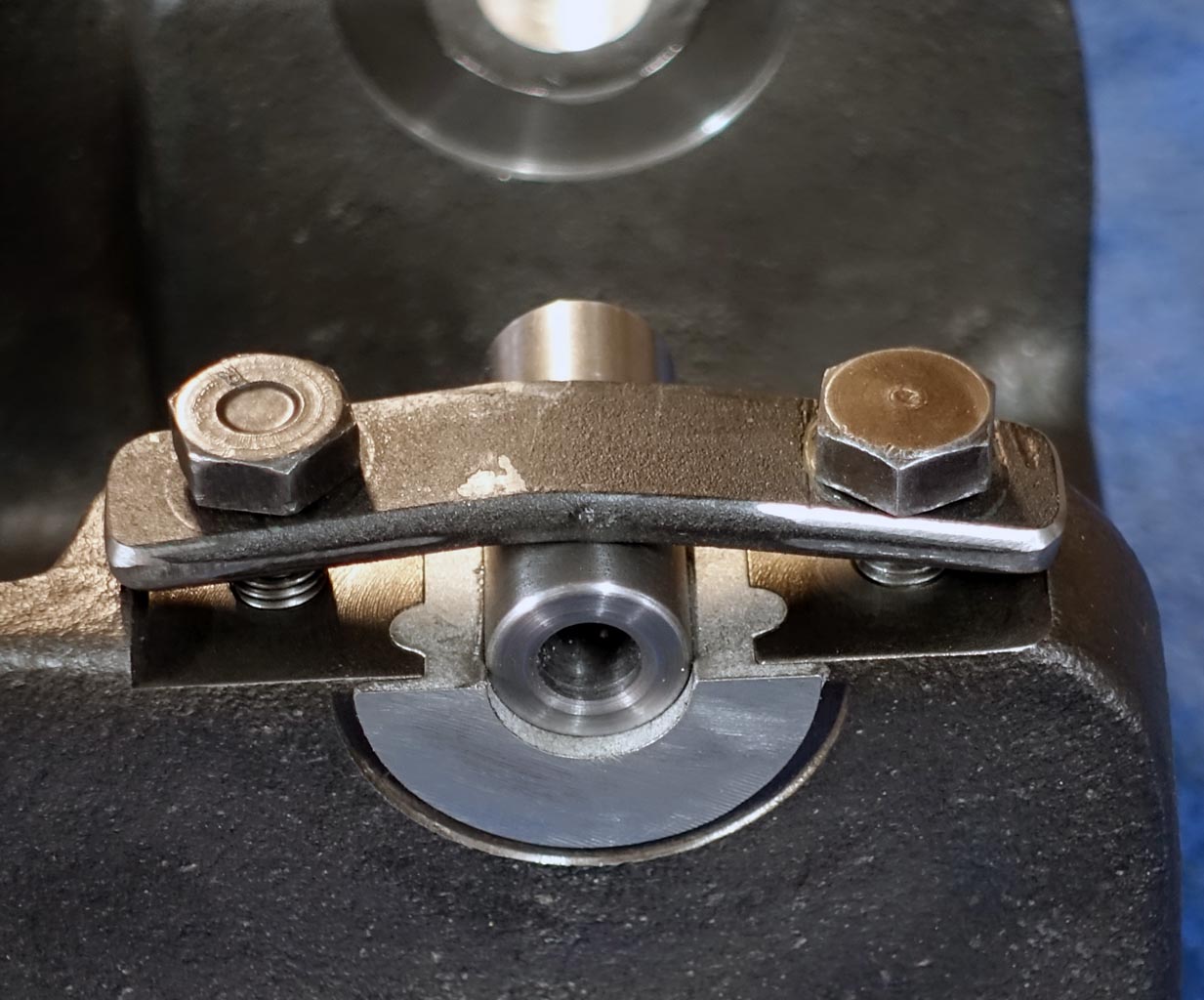
Hi Gabby,
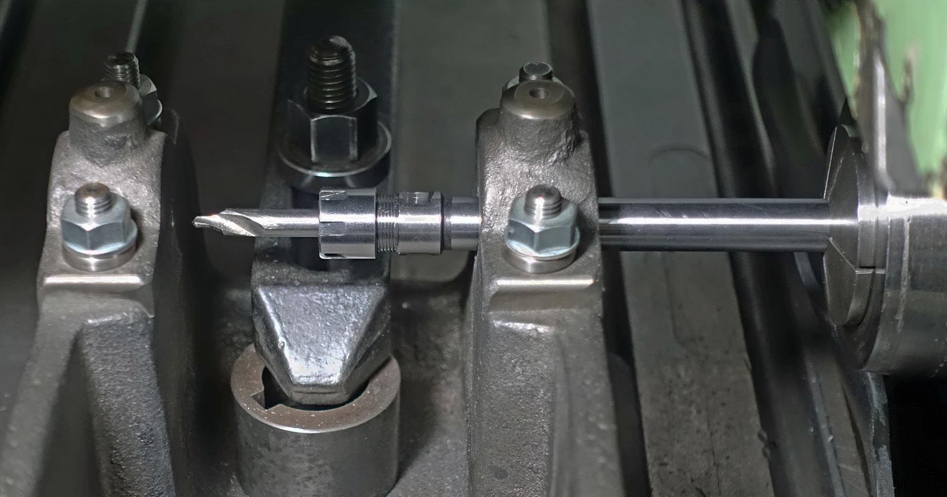
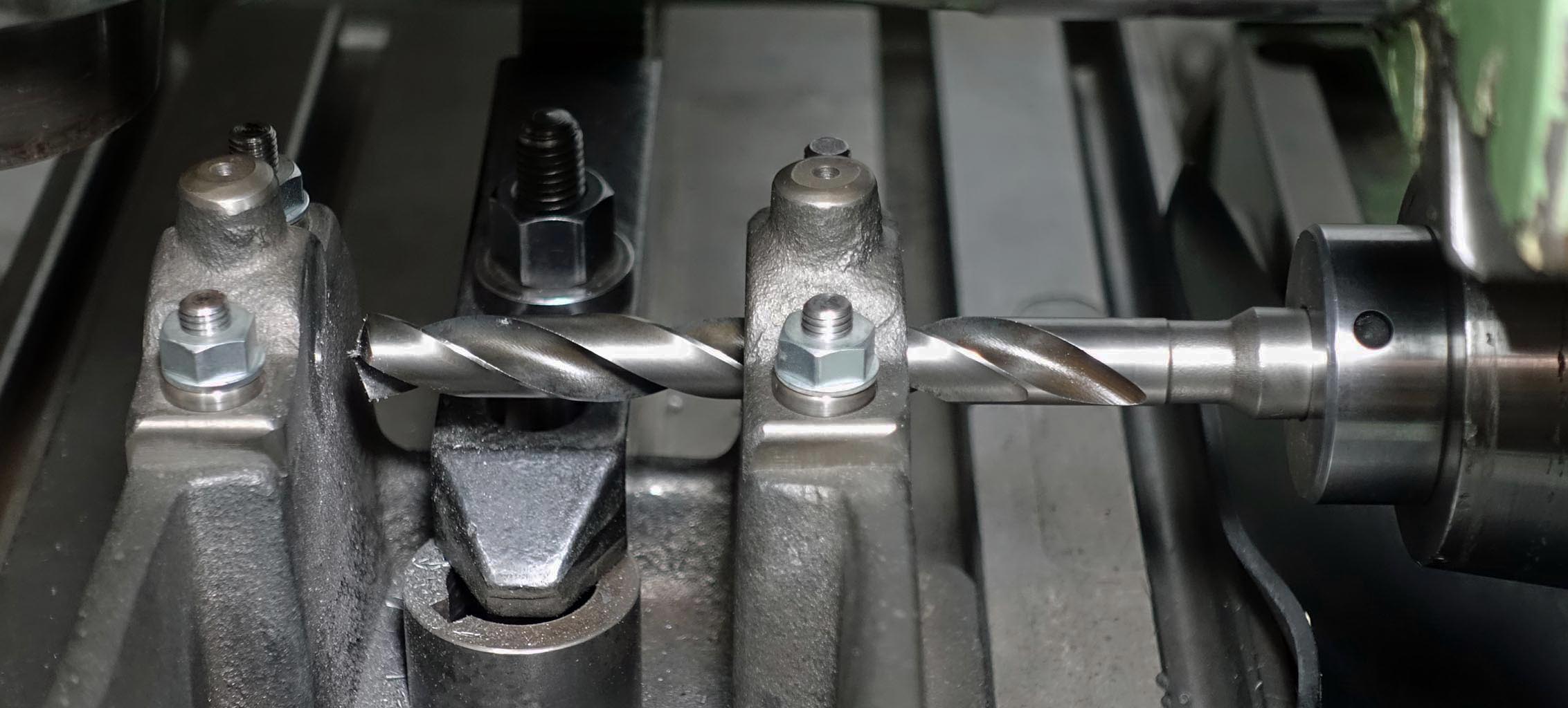
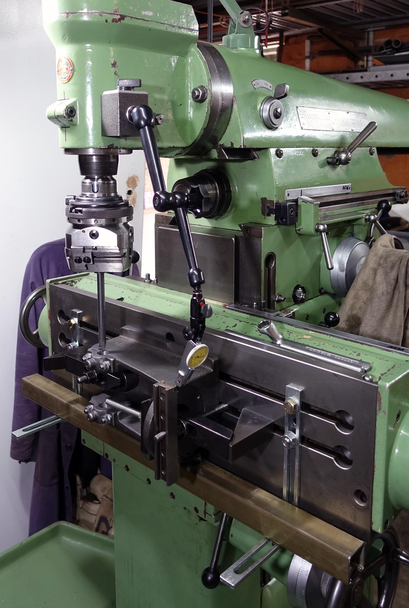
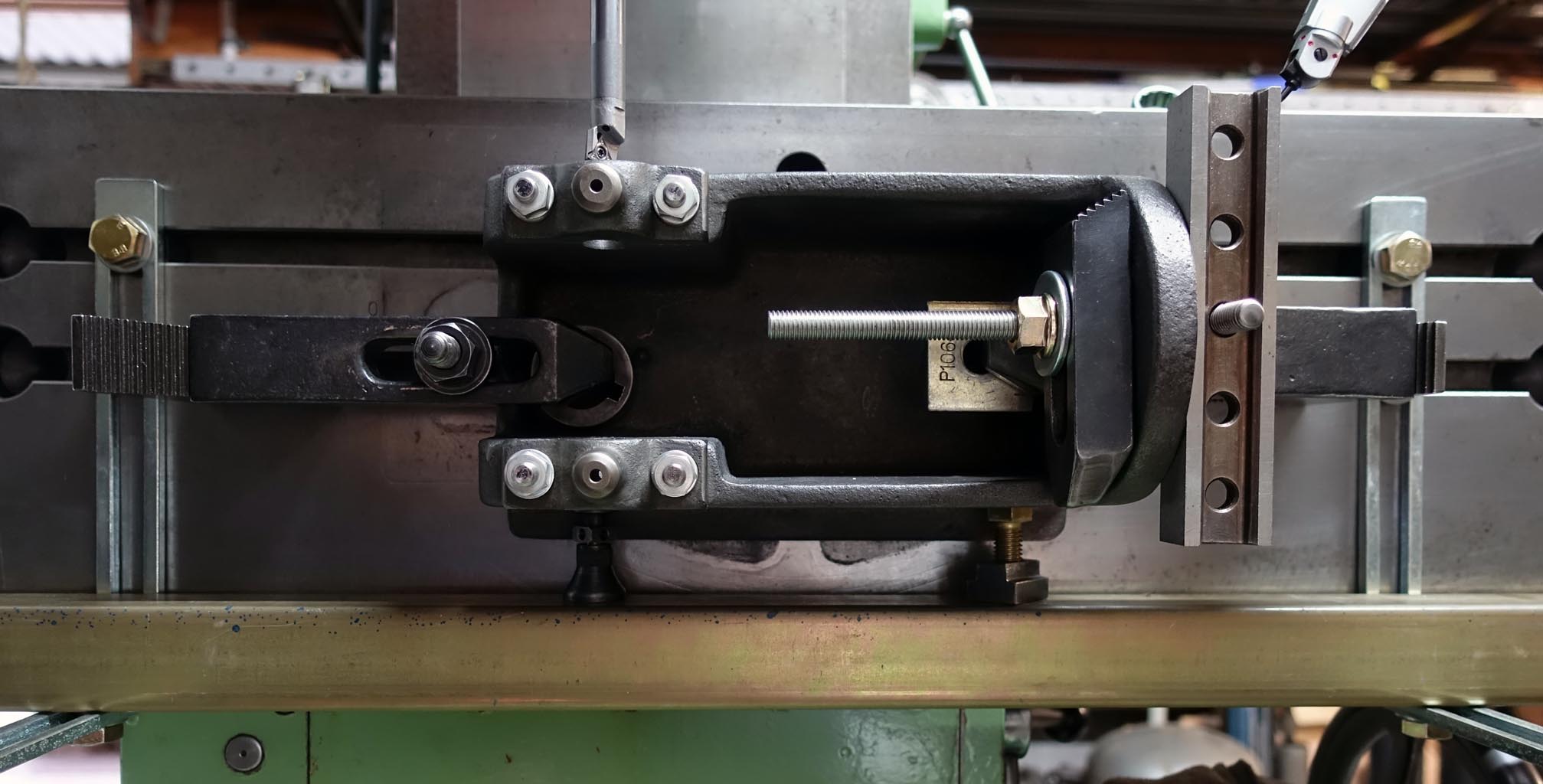
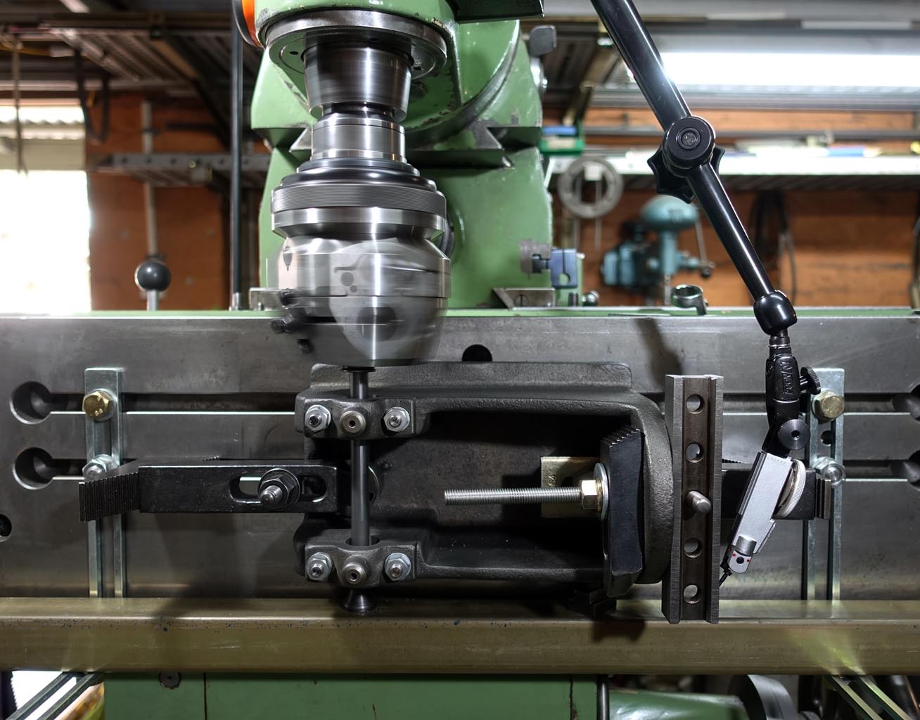
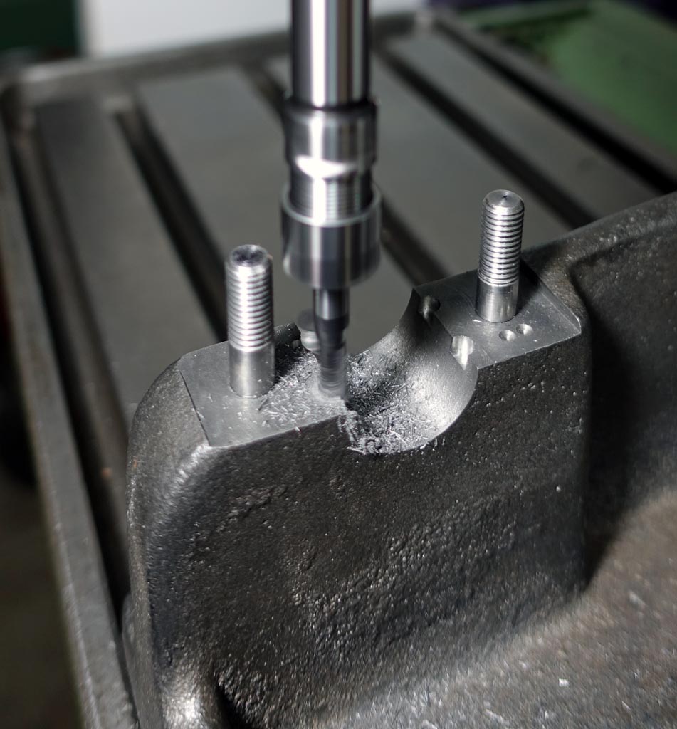
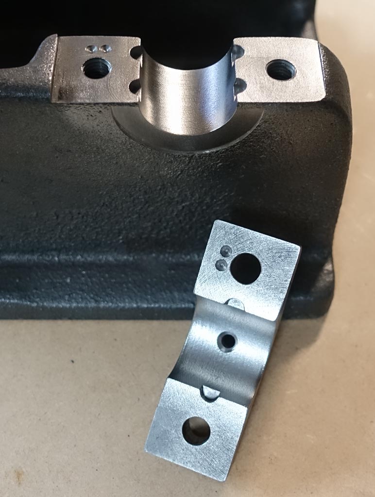
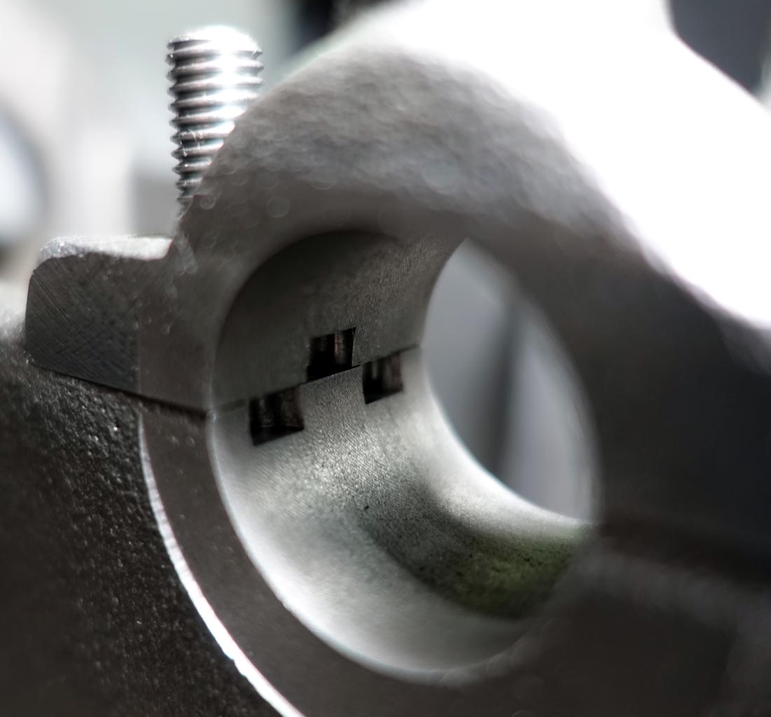
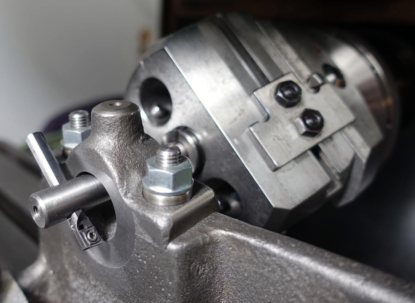
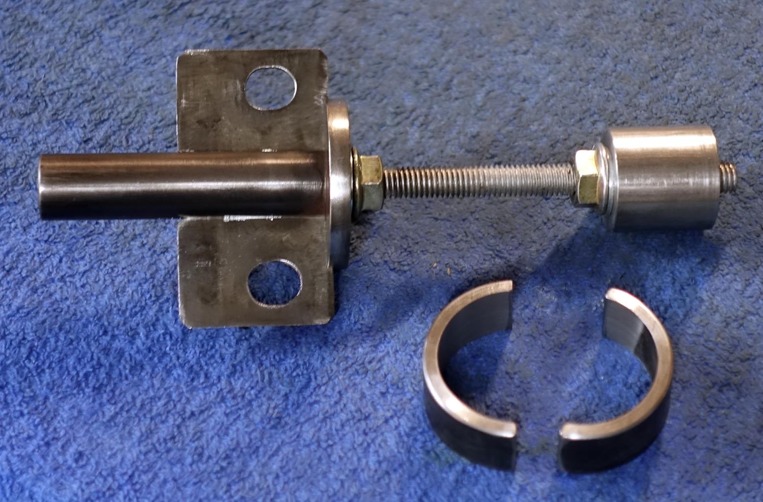
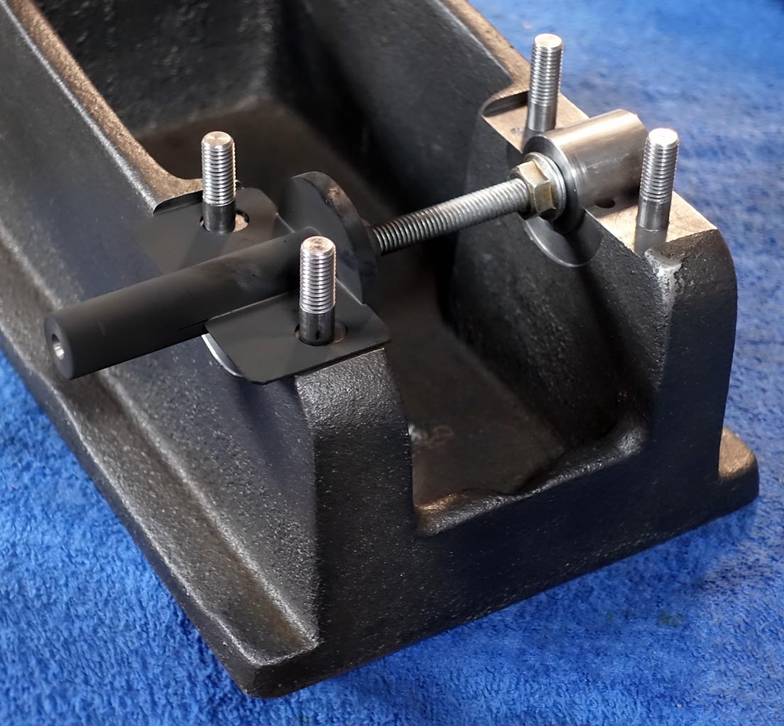
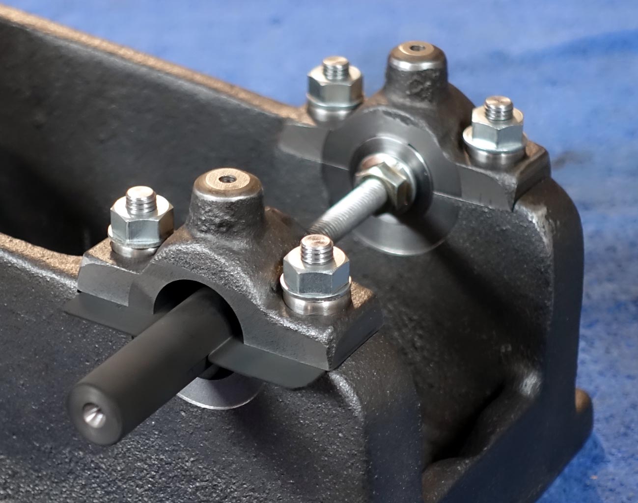
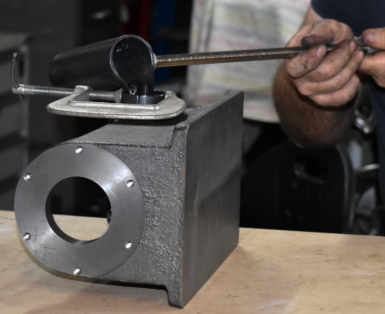
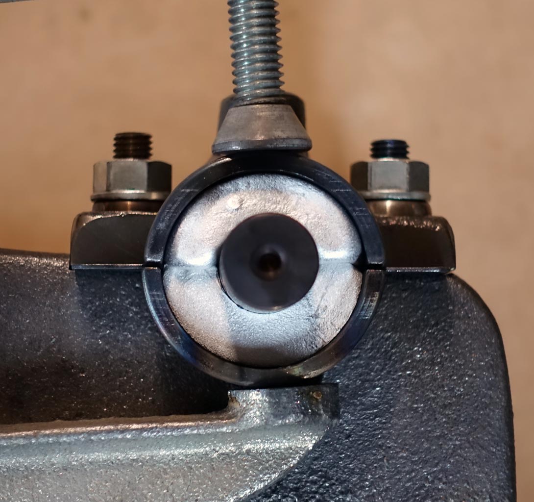
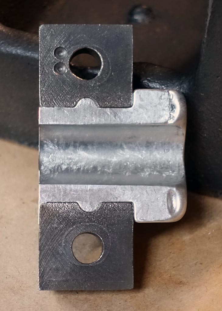
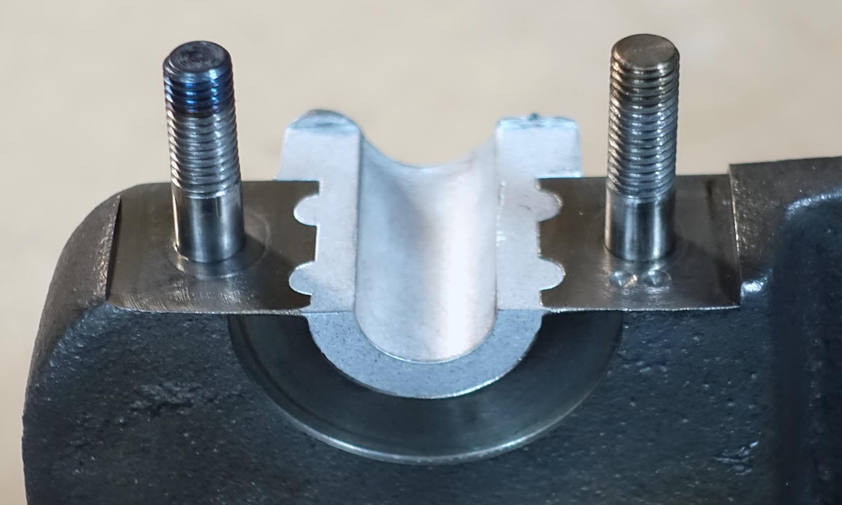
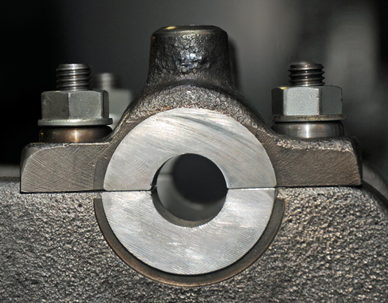
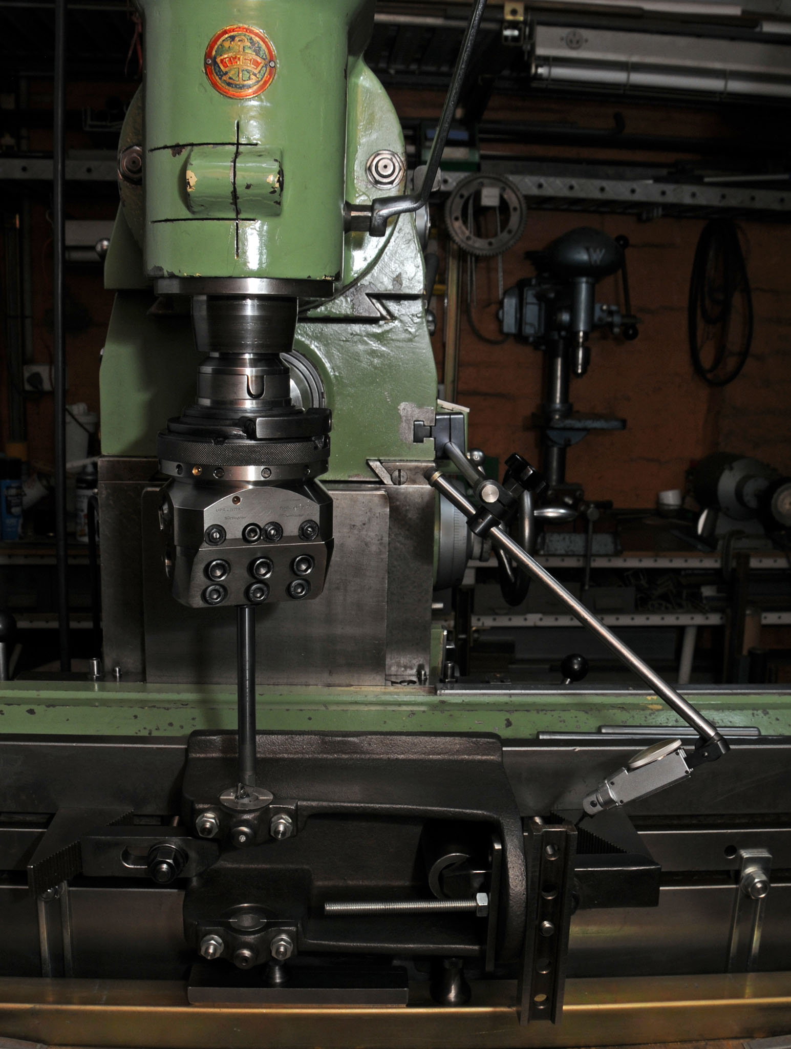
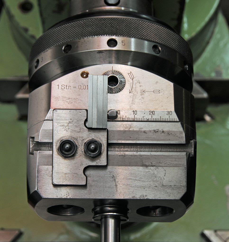
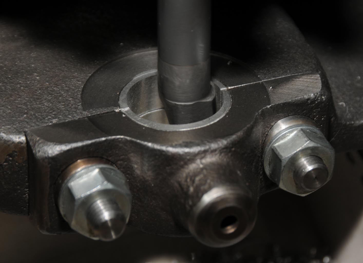
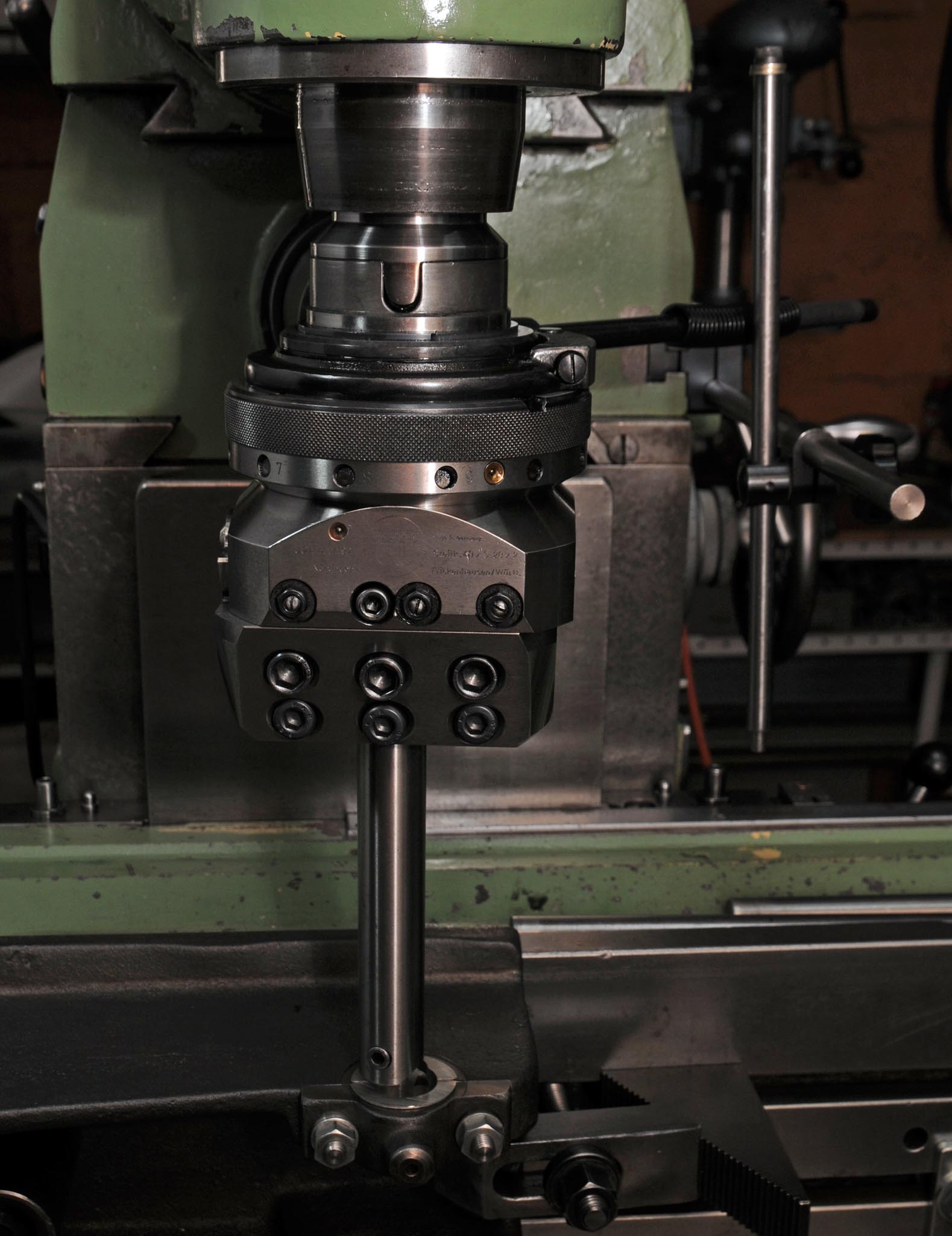
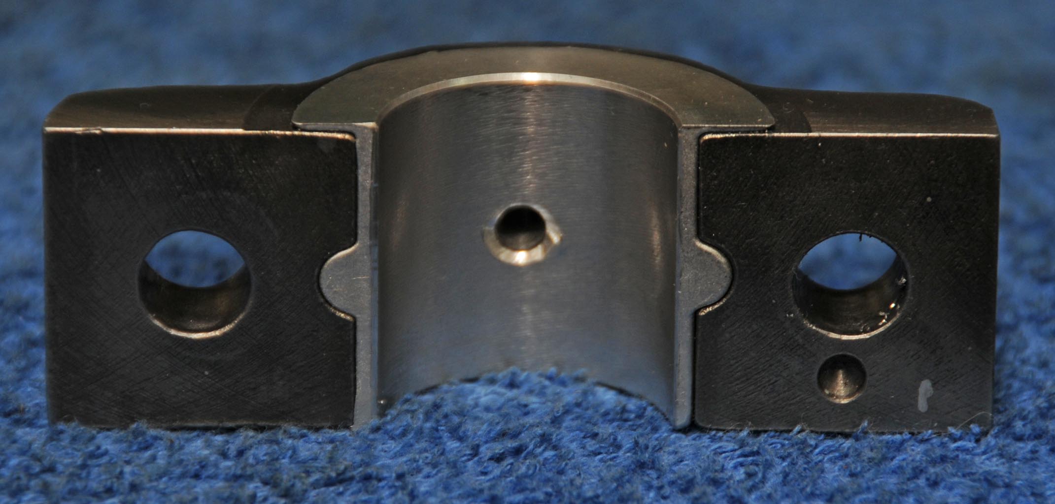
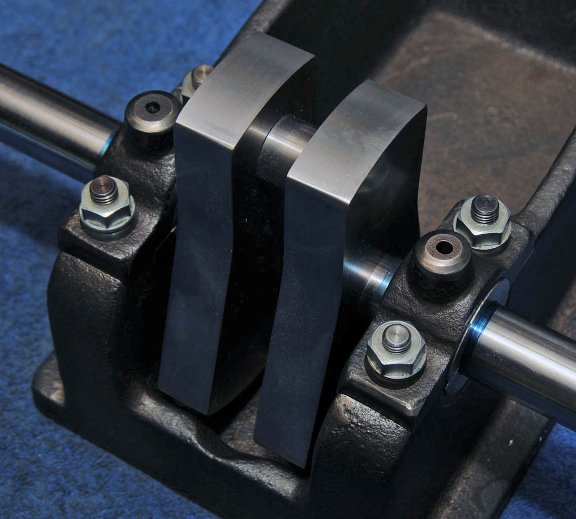
No mate, the thread hasn't ended I'm just a bit slow with updates and I'll probably still be working on this engine in five years time the way things are going.
I don't think the castings are commercially available, Len had enough made for the engines he built himself and he sold a few sets of castings but I don't think he has had any more made.
There is a youtube clip of the first engine Len built running here:
[ame]https://www.youtube.com/watch?v=CXZT9fuwoMw[/ame]
Cheers,
Greg.