arnoldb
Well-Known Member
- Joined
- Apr 8, 2009
- Messages
- 1,792
- Reaction score
- 12
One of the accessories that's lagging for my mill is a boring head.
I could buy one, but that would not be nearly as much fun as building my own; some of you might have guessed by now from previous projects that I like building my own tools ;D
Once again, Dean's boring head build serves as an inspiration, and I'll also build my unit based on Steve C's (walnotr) plans; changed to meet my requirements - Thanks guys!
Some of the key areas of departure from Steve's plans for me will be:
1. Size - I'll be building at about 150% of the original size. This is for a couple of reasons; I have a bigger mill, so could do with a bigger boring head. The boring bar set I have has 12mm shanks, so the head needs to be bigger to accommodate this.
2. Metric - I prefer to work in metric, so the head's leadscrew will be metric. I've chosen a 0.5mm pitch for it, as it means that for every full turn of the screw, the head will be offset by 0.5mm - and thus take a cut of 1mm in diameter from a workpiece. Also, all screws used will be metric.
The mounting for the boring head had me thinking for a bit as well; initially, I considered fitting it with a 16mm shank to use in the mill's collet chuck, but that is not the best option. So I'll settle for making the shank MT4 to suit my mill's spindle directly - that would be the best long-term solution.
I'll be posting "warts & all" - so some members might be bored with the build; my apologies for that in advance.
And any suggestions and/or questions during the build is welcome!
This is what I have to start off with in terms of materials:
A bit of 32mm HRS rod for the MT4 shank, a bit of 60mm cast iron for the body (I might not use this; I'll try and find steel instead), a bit of 60mm steel offcut for the slide/holder, bits of brass for the gib and lead screw retainer, and silver steel for the leadscrew.
As I'm still trying to find some steel for the body rather than use the cast iron, I started off with the shank today. The rod I have is pretty close to the size needed for an MT4 adapter, so there's not a lot of room for removing material, but the surface scale has to go. First I center drilled one side of the 32mm rod as accurately as possible for tailstock support by clamping the stock upright on the drill press - this will become the "thin" end of the taper, as it is not spot-on center. I know the inside jaws of my 3-jaw chuck is pretty accurate at this size, so the end in the chuck would be very close to centered. Here I've turned down some of the scale - as you can see, the bit close to the chuck is more on center:
At this point I stopped turning down the scale, as I didn't want the bit close to the chuck turned down any further.
Next I turned a section at the tailstock end down to 24mm - below the minimum that would be needed for the taper:
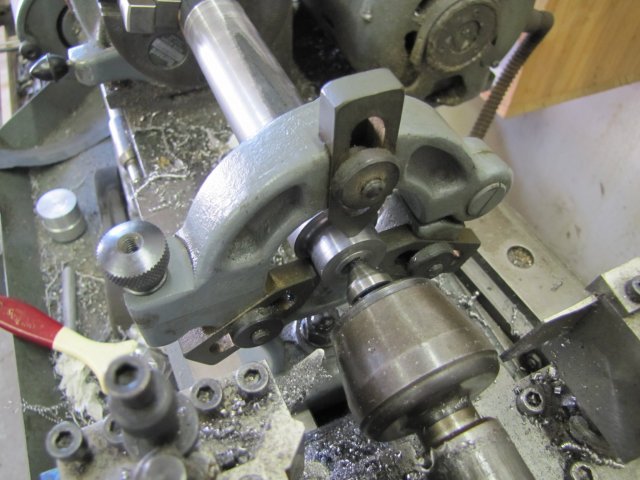
This end will become the "Draw-bar" end of the shank. Once there is a taper in play, workholding becomes difficult, so I decided to finish the draw-bar end completely, including threading it. With a long overhang needing support and working from the end, I brought out the fixed steady. It's one of those accessories that's seldom seen in use, but can be worth its weight in gold when needed. Here I'm setting it up - with the workpiece supported by the tailstock center, it's easy; just push each of the steady "fingers" lightly against the turned flat and tighten up the fingers:
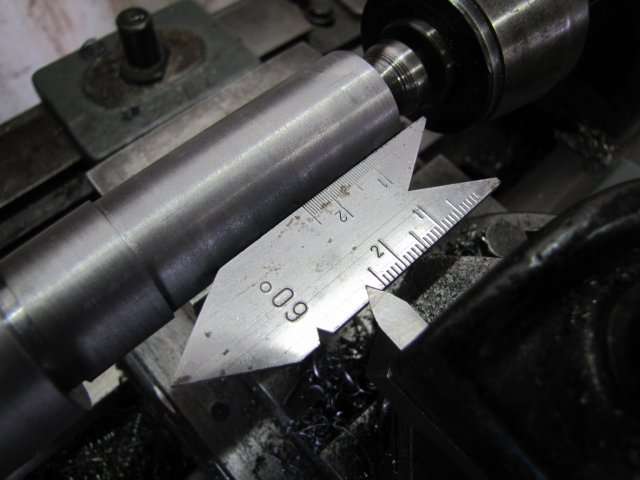
A squirt from the oil can to lubricate the steady fingers, and a reduction in speed (I work at a slower turning speed when the steady is in use), and I could drill the end out to 10.2mm for a good depth - about 60mm deep. This is for tapping M12 drawbar thread. Then, with the topslide set over to 30 degrees, I turned a good bit of taper (about 14mm OD at the end) on the end with a boring bar:
Next I tapped the thread - I started of with the #1 12mm tap gripped in the tailstock chuck, and threaded in for a bit - this was to make sure the thread is started straight. Then I just opened the chuck, added the T-handle, and continued:
The taper tap was followed by the 2nd and 3d taps as well.
I then reversed the workpiece on the lathe, and set up the fixed steady on the "clean" bit that was close to the chuck earlier.
This is where a seldom mentioned bit of using fixed steadies comes into play. They are GREAT for getting an accurately center drilled workpiece at a distance away from the chuck. The workpiece is just very lightly chucked initially, and the steady fingers closed a bit at a time, followed by manually turning the chuck through a full revolution after each adjustment. The workpiece was off-center at the steady end completely - by about 1.5mm, but the gradual closing of the fingers and the fact that it's lightly gripped in the chuck causes it to center on its own.
Once all three of the fingers were lightly in contact, the chuck was tightened up a bit more; not too much though; just tight enough to grip the workpiece for center-drilling it. Even if the steady fingers keeps the workpiece slightly off-center, a good center hole is drilled; it will just be a bit over-size ;D:
You may be wondering by now why I made all the boo-hah about boring an oversize 30 degree angle on one side of the workpiece and then going through the process of setting up the steady to drill the center hole on the other end...
Well, it all was to get to a point where I could mount the workpiece between centers:
Instead of fussing around with binding wire, I just used a cable-tie to tie the drive dog to the catch-plate.
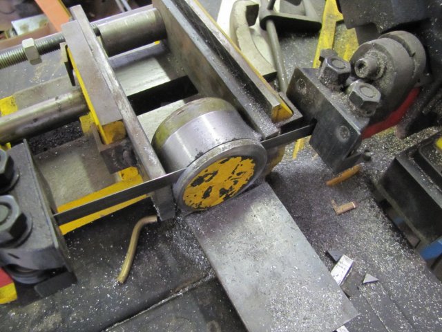
And why did I need it between centers? - well, to turn the taper... I'm fortunate that I have a taper turning attachment (TTA) for my lathe. Setting over the topslide was not an option for an MT4 taper; the topslide does not have enough travel to turn it. And I needed a way to reliably take the workpiece off the lathe to test it in the milling machine spindle for fit. Did I mention that this is the first time I've tried to turn a Morse Taper ?
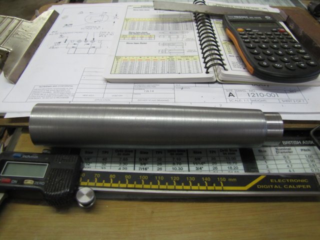
For the first time since I got my lathe, I'm using the TTA - well for it's intended use anyway; it's a great place to mount a magnetic base for centering jobs in the 4-jaw chuck otherwise . My little "Engineering Black Book" gives specifications for MT4 in metric, so I used the specs to calculate that I would need a taper of 5.124 mm for a travel distance of 100mm (I think this is right; the black book is in the shop now!) Well, there's no way I can measure accurately to 1/1000th of a mm, so 1/100 and an eyeball deviation on the DI would have to do. This is the setup I used:
The dial indicator is mounted on the TTA link to the cross-slide, as squarely and on center to the workpiece as I could get it by eye :big:, and run over a measured 100mm "clean" bit of the workpiece to get the readings and set the TTA. Not very professional, I know, but I think good enough for "close enough"; it's not going on a space mission.
I started cutting the taper, and after the second cut things looked wrong. The taper was WAAAY too steep!. I had the correct figures, but forgot to halve the diameter while setting the TTA :-[. Fortunately, there was more than enough un-turned stock available to re-set to cut at half the angle. Just more work to get the TTA set.
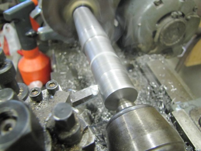
Things went well from there, and I cut close to size. Then I did a test. First some (too much!) Prussian Blue on the shaft:
After a light fit-and-turn in the mill spindle:
By no means perfect, but close enough for me. You'll see that the contact area on the larger diameter was closer, meaning that my taper is slightly shallow - but pretty close.
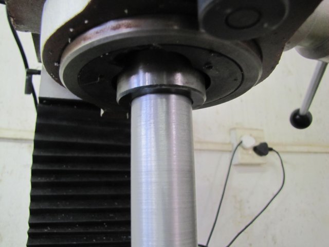
At least the shank sits in the mill on its own with just a light push; pretty much the same as the rest of my mill accessories:
I had to use a hammer with the draw-bar to tap it out, so as far as I'm concerned, the fit is a good 'un.
While dismantling the cross-slide to TTA link, I brushed my thumb knuckle across the slot linking the two... The Myford tooling is invariably very well machined and finished with all sharp edges removed, but someone didn't take the sharp edges off that slot... I'll have to now :big: With red stuff leaking from the skinned bit of said knuckle, I called it quits for the day - Not much to show, but some progress none-the-less:
Regards, Arnold
I could buy one, but that would not be nearly as much fun as building my own; some of you might have guessed by now from previous projects that I like building my own tools ;D
Once again, Dean's boring head build serves as an inspiration, and I'll also build my unit based on Steve C's (walnotr) plans; changed to meet my requirements - Thanks guys!
Some of the key areas of departure from Steve's plans for me will be:
1. Size - I'll be building at about 150% of the original size. This is for a couple of reasons; I have a bigger mill, so could do with a bigger boring head. The boring bar set I have has 12mm shanks, so the head needs to be bigger to accommodate this.
2. Metric - I prefer to work in metric, so the head's leadscrew will be metric. I've chosen a 0.5mm pitch for it, as it means that for every full turn of the screw, the head will be offset by 0.5mm - and thus take a cut of 1mm in diameter from a workpiece. Also, all screws used will be metric.
The mounting for the boring head had me thinking for a bit as well; initially, I considered fitting it with a 16mm shank to use in the mill's collet chuck, but that is not the best option. So I'll settle for making the shank MT4 to suit my mill's spindle directly - that would be the best long-term solution.
I'll be posting "warts & all" - so some members might be bored with the build; my apologies for that in advance.
And any suggestions and/or questions during the build is welcome!
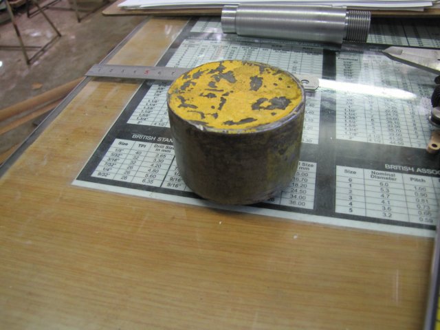
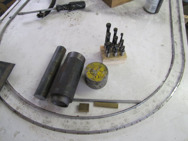
This is what I have to start off with in terms of materials:
A bit of 32mm HRS rod for the MT4 shank, a bit of 60mm cast iron for the body (I might not use this; I'll try and find steel instead), a bit of 60mm steel offcut for the slide/holder, bits of brass for the gib and lead screw retainer, and silver steel for the leadscrew.
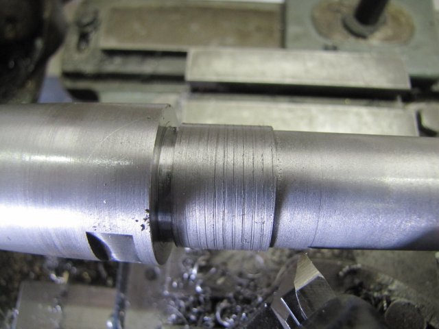
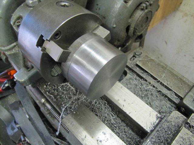
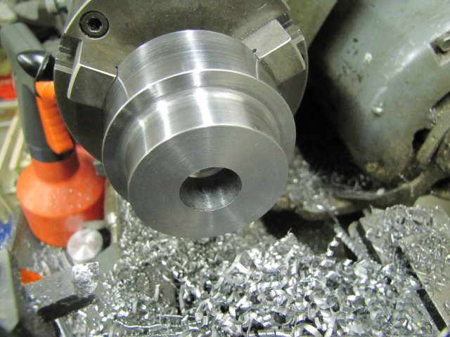
As I'm still trying to find some steel for the body rather than use the cast iron, I started off with the shank today. The rod I have is pretty close to the size needed for an MT4 adapter, so there's not a lot of room for removing material, but the surface scale has to go. First I center drilled one side of the 32mm rod as accurately as possible for tailstock support by clamping the stock upright on the drill press - this will become the "thin" end of the taper, as it is not spot-on center. I know the inside jaws of my 3-jaw chuck is pretty accurate at this size, so the end in the chuck would be very close to centered. Here I've turned down some of the scale - as you can see, the bit close to the chuck is more on center:
At this point I stopped turning down the scale, as I didn't want the bit close to the chuck turned down any further.
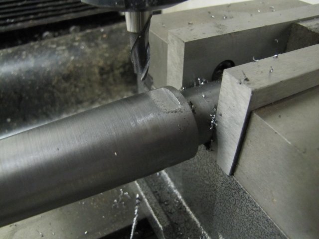
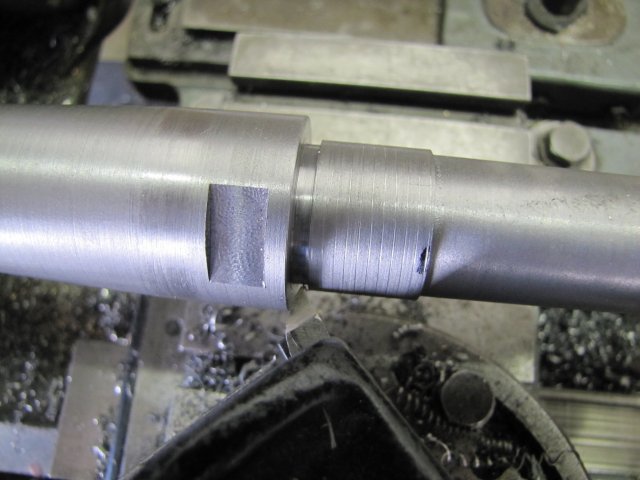
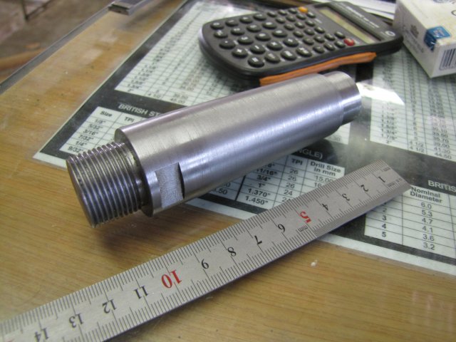
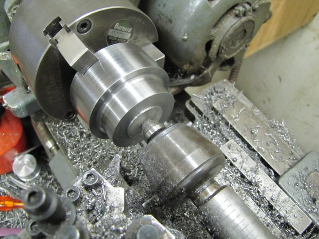
Next I turned a section at the tailstock end down to 24mm - below the minimum that would be needed for the taper:
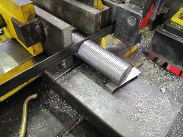
This end will become the "Draw-bar" end of the shank. Once there is a taper in play, workholding becomes difficult, so I decided to finish the draw-bar end completely, including threading it. With a long overhang needing support and working from the end, I brought out the fixed steady. It's one of those accessories that's seldom seen in use, but can be worth its weight in gold when needed. Here I'm setting it up - with the workpiece supported by the tailstock center, it's easy; just push each of the steady "fingers" lightly against the turned flat and tighten up the fingers:
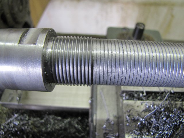
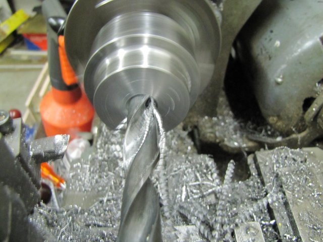
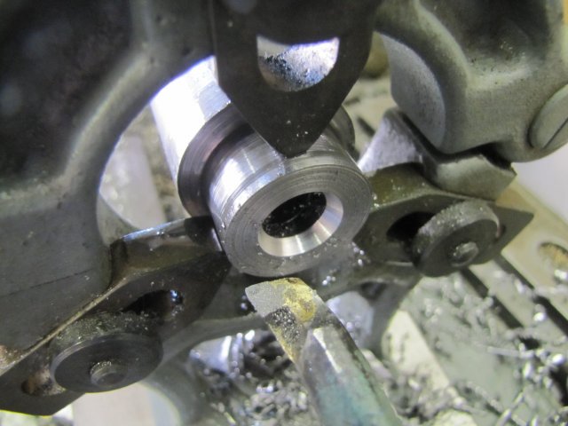
A squirt from the oil can to lubricate the steady fingers, and a reduction in speed (I work at a slower turning speed when the steady is in use), and I could drill the end out to 10.2mm for a good depth - about 60mm deep. This is for tapping M12 drawbar thread. Then, with the topslide set over to 30 degrees, I turned a good bit of taper (about 14mm OD at the end) on the end with a boring bar:
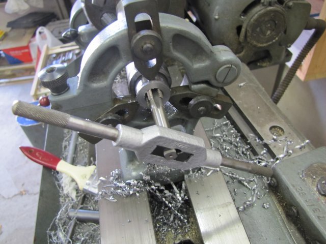
Next I tapped the thread - I started of with the #1 12mm tap gripped in the tailstock chuck, and threaded in for a bit - this was to make sure the thread is started straight. Then I just opened the chuck, added the T-handle, and continued:
The taper tap was followed by the 2nd and 3d taps as well.
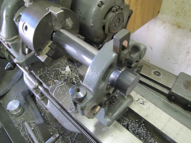
I then reversed the workpiece on the lathe, and set up the fixed steady on the "clean" bit that was close to the chuck earlier.
This is where a seldom mentioned bit of using fixed steadies comes into play. They are GREAT for getting an accurately center drilled workpiece at a distance away from the chuck. The workpiece is just very lightly chucked initially, and the steady fingers closed a bit at a time, followed by manually turning the chuck through a full revolution after each adjustment. The workpiece was off-center at the steady end completely - by about 1.5mm, but the gradual closing of the fingers and the fact that it's lightly gripped in the chuck causes it to center on its own.
Once all three of the fingers were lightly in contact, the chuck was tightened up a bit more; not too much though; just tight enough to grip the workpiece for center-drilling it. Even if the steady fingers keeps the workpiece slightly off-center, a good center hole is drilled; it will just be a bit over-size ;D:
You may be wondering by now why I made all the boo-hah about boring an oversize 30 degree angle on one side of the workpiece and then going through the process of setting up the steady to drill the center hole on the other end...
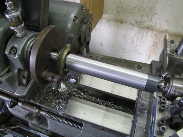
Well, it all was to get to a point where I could mount the workpiece between centers:
Instead of fussing around with binding wire, I just used a cable-tie to tie the drive dog to the catch-plate.
And why did I need it between centers? - well, to turn the taper... I'm fortunate that I have a taper turning attachment (TTA) for my lathe. Setting over the topslide was not an option for an MT4 taper; the topslide does not have enough travel to turn it. And I needed a way to reliably take the workpiece off the lathe to test it in the milling machine spindle for fit. Did I mention that this is the first time I've tried to turn a Morse Taper ?
For the first time since I got my lathe, I'm using the TTA - well for it's intended use anyway; it's a great place to mount a magnetic base for centering jobs in the 4-jaw chuck otherwise
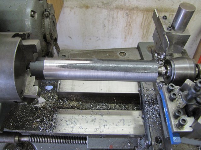
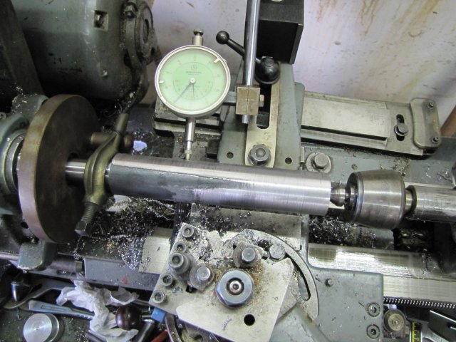
. My little "Engineering Black Book" gives specifications for MT4 in metric, so I used the specs to calculate that I would need a taper of 5.124 mm for a travel distance of 100mm (I think this is right; the black book is in the shop now!) Well, there's no way I can measure accurately to 1/1000th of a mm, so 1/100 and an eyeball deviation on the DI would have to do. This is the setup I used:
The dial indicator is mounted on the TTA link to the cross-slide, as squarely and on center to the workpiece as I could get it by eye :big:, and run over a measured 100mm "clean" bit of the workpiece to get the readings and set the TTA. Not very professional, I know, but I think good enough for "close enough"; it's not going on a space mission.
I started cutting the taper, and after the second cut things looked wrong. The taper was WAAAY too steep!. I had the correct figures, but forgot to halve the diameter while setting the TTA :-[. Fortunately, there was more than enough un-turned stock available to re-set to cut at half the angle. Just more work to get the TTA set.
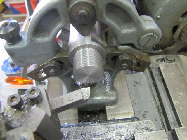
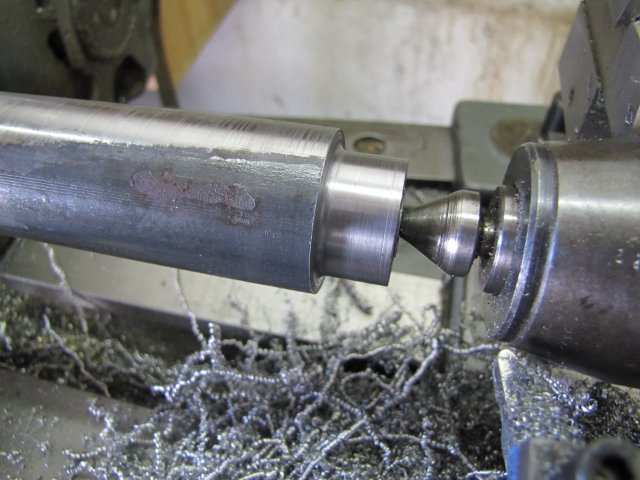
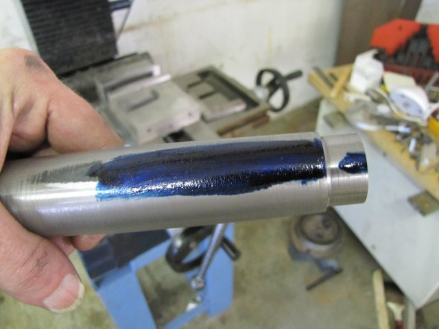
Things went well from there, and I cut close to size. Then I did a test. First some (too much!) Prussian Blue on the shaft:
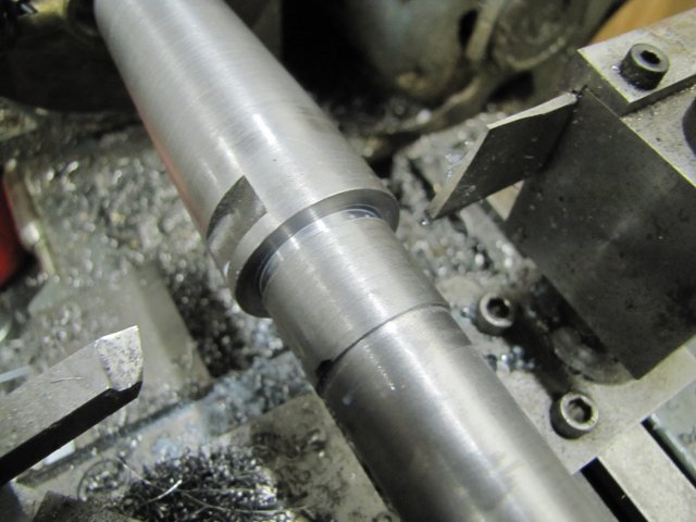
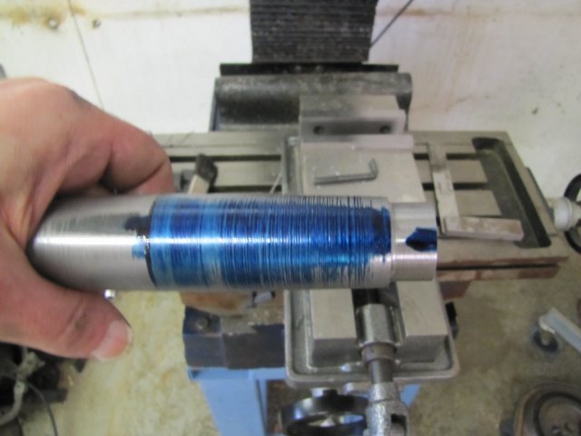
After a light fit-and-turn in the mill spindle:
By no means perfect, but close enough for me. You'll see that the contact area on the larger diameter was closer, meaning that my taper is slightly shallow - but pretty close.
At least the shank sits in the mill on its own with just a light push; pretty much the same as the rest of my mill accessories:
I had to use a hammer with the draw-bar to tap it out, so as far as I'm concerned, the fit is a good 'un.
While dismantling the cross-slide to TTA link, I brushed my thumb knuckle across the slot linking the two... The Myford tooling is invariably very well machined and finished with all sharp edges removed, but someone didn't take the sharp edges off that slot... I'll have to now :big: With red stuff leaking from the skinned bit of said knuckle, I called it quits for the day - Not much to show, but some progress none-the-less:
Regards, Arnold