British 0-4-0 Toy Locomotive: he said

Home Model Engine Machinist Forum

Help Support Home Model Engine Machinist Forum:

This site may earn a commission from merchant affiliate links, including eBay, Amazon, and others.
Zee,
After much searching I found the original magazine articles. Feb,Mar and Apr 1976 Live steam.
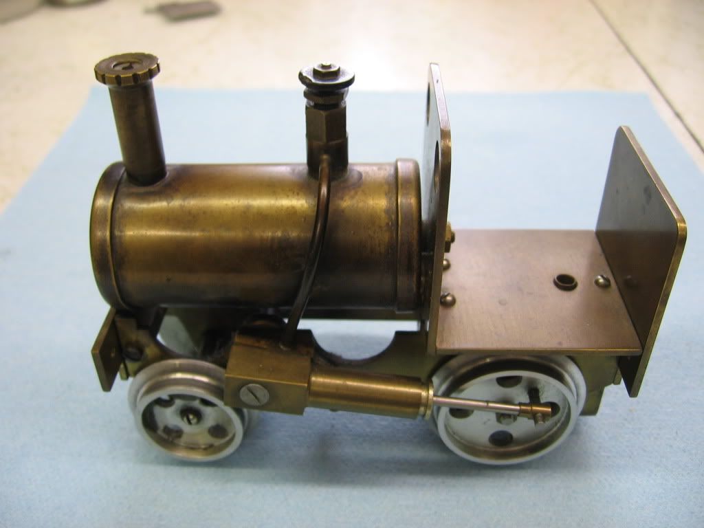
The boiler shell is specified as 1 1/4 inch od with a 0.035" wall. The end caps are specified as 1/32 inch brass. The brass ends are annealed and hammered into shape over aluminum formers using a soft faced hammer and working in several stages with annealing at each step. The safety valve is set at 10 psi according to the magazine article.
It's a very tame banshee, at least mine were. Of course I was a rank beginner when I made the pair.
The alcohol burner wicks can give some control over the speed and can be blown out to stop it (so the article says.) I guess now I'll have to get it going again, I think my safety valve is leaky.
I may remember more later. Ask if I'm unclear.
Have fun with it.
Dave

 
Twmaster said:
Some how I have an image of Zee in my mind telling the family 'stand outside, I'm gonna light this sucker!'
mklotz said:
Here, hold my beer M&Ms and watch this!
bearcar1 said:
"somebody call 911!" ............ uh operator, yes, I'd like to report a fire....
Deanofid said:
"Wake up, honey. You've never seen an explosion like this!"

Make one little part and people start setting expectations. :big:

Thanks tmuir. Since this is a drain extension pipe for the boiler, it is clad in chrome. I have to remove it from the ends so the end caps can be soldered on. It will take some careful sanding.

Thanks for the link Sean.

Neat stuff Dave. For this kit, the boiler is also 1 1/4...when I get one I'll measure the wall - just to see how it compares. The brass end caps for this kit are turned rather than shaped.
 
Zee, old super "O" track for your new, later loco, 31" radius...

ebay 140384079979

Paul
 
Hi Zee and all,

I, like Dave, made one of the little steam locos back in the late 70's. Dickens is what they call it in Live Steam Magazine. If you notice on the photo I added a steam valve at the boiler outlet. I don't think the original plans called for one, but it is quite useful in taming the beast. Mine ran well, actually too well, on making a curve it tipped off the track and immediately burst in to flames. Luckily I was running it on a concrete floor, if on carpet, 911 may have been in order! Ten psig is plenty, I personally wouldn't press a brass boiler any higher. You have done a beautiful job, I love the polish. Mine on the other hand has that patina stuff (read neglected cleaning and polishing :)) all over it. If I can be of any help (polishing excluded) please let me know.

engines059.jpg


Chris
 
Thanks Paul.
Nice looking model Chris.

I'm glad to see a few of you have built this loco. I was beginning to wonder if it was real or not.

I made 4 more of the bumpers. I'm pretty happy with them. However, I think they indicate a problem in the lathe or my cutting. There are concentric circles on the disk. After polishing...they actually look pretty neat. (There is a problem with the lathe...speed seems to vary quite a bit without changing setting...we'll see what happens once I get my order of transistors in.)

I also made the doo-hickey that is used to attach a tire pump for hydro testing. Well..not finished...I need to get a 1/4-28 die to do the thread...and then it's finished.

No pics! Sorry. Camera is no good with Macro. Wife comes home this weekend and I can get my good camera back!
 
Some progress...first the promised pic...

By the way...one should hug one's wife when she gets home from a two week trip instead of first saying "where's the camera?". ;D

Thought you should know. I got it backwards. So it took a while longer to use the camera.

1e7798b8.jpg


The one brass part looks a little chattery. It's the dummy steam dome for testing so I wasn't real careful.

Worked on the frames today. All that's left is to cut the contour and clean it. I used my milling clamps as a stop and did each piece separately...a hole at a time. I worried that doing both together might cause one to pull up into chuck...not a good thing. Later I thought I might have been able to bolt them together.

You'll notice one of the holes seems 'burned'. I'm not sure what happened. It was apparent on the first bit I used that it was dull. I went to a second, and although it cut, I think it wasn't sharp enough. That's when the 'burn' happened. A third bit worked great.

For the pic, the parallels are in the 'start' position. You can the one under the slot. When I cut the slot I had the parallel at an angle with packing to make sure it didn't move.

The instructions talked about using a center drill then drill in a chuck, and then to change to a collet and end mill the slot by plunge cutting. I used the center drill and drill in a collet. That let me get closer just in case the column/head wasn't right.

But...they came out great. Everything lines up nicely when put together.

c4a26227.jpg

 
Carl,
Looking good. This is a really interesting project. I'm not a fan of drilling stacked pieces either. Not only because of holding issues, but also because it's easy to have the drill bit wander.
Keep it up!
Dennis
 
Glad your missus is home safe, again, Zee.

The bits are looking good! Only problem I can see is, you have cooler M&M paraphernalia than I.

Dean
 
Great work so far. I'm glad to see this loco going together. :bow:


Nice start Zee. Will be watching in the wings.

Instructions? Whats are those? :big: :big: :big:

Ron

 
Thanks Dennis.
Thanks Dean. It helps that I used to work for them.
Vernon...yeah. ;D
Thanks Ron.

I finished the frames...it took a change of pants, some dome scratching, a little help from a buddy (read rat)...

I'll show pics once I have them cleaned up...but I'm going to wait to do that as I expect to mar them up as I proceed.

I was so proud...I took them upstairs to show them off...

She said..."You should have known from the measurements you wouldn't be able to sit on it."

There was no point in trying to explain.
 
zeeprogrammer said:
I was so proud...I took them upstairs to show them off...

She said..."You should have known from the measurements you wouldn't be able to sit on it."

There was no point in trying to explain.

Now, that's a Coke-out-of-the-nose snort 'n giggle if I've ever heard one. What a gal.
Excuse me while I change my shirt and clean up around here...

Dean
 
Hi Carl
That's a nice project you picked to make.
Yesterday I attended the NEMES show in Massachusetts. Many talented people there with great models. Last year there was a man there set up on a round table with a track. He was running a model like the one you are building. There were a bunch of children standing at the table watching with amazement as the little engine run around the track. I didn't see him there this year. I wish you luck with yours you seem to be off to a good start. Jack B
 
Thanks Dean.
Thanks Jack...
Jack B said:
There were a bunch of children standing at the table watching with amazement as the little engine run around the track.
Yeah...a lot of joy in that.

This kit doesn't have the blow-by-blow instructions that the prior two kits have. (Please keep the cheering down folks.) So I'm left to my own devices and what I've learned from those two kits and this forum.

That's not a bad thing.

Please point out better methods, incorrect technique, the right technique, etc. It is all very welcome. (Zeepster only learns from oopsters when they're pointed out.)

Today I made the 4 brass stretchers. I cut a piece of 1/4" bar into 4 pieces and milled them all together to length. A tad short but they should do.

Then it was holes and tapping. I did them in stages. First I drilled all the holes that were the same distance from the end. Then swapped out the chuck for a collet to hold the tapping tool and tapped them all. Then I did the center hole the same way, and finally the holes on the ends.

Here's a pic of my setup for the holes near the ends. The near parallel is stuck to the vise with double-stick tape. The far parallel was used to sit the part and then moved out far enough for drilling. Once the Y axis was set, I never had to change it. Only had to set X 3 times.

496b9272.jpg


When I did the holes on the ends, I just pressed the part up against the stop. Probably not the most square but the distance for tapping is quite small so I didn't think the error would matter.

Here's a pic of the stretchers and the frames...I won't polish them them up until later...

1b98c5bf.jpg


And for fun I put what I had together...

7c4210e6.jpg


I was real happy to have made the Z extension mod on my X2. The extra one inch sure makes a difference.

Whatever mistakes I may have made...I was real happy with today's work. I can tell that the investment you all have made in me is taking hold.

hm..looking at that last pic reminds me...

When I did the slot, I drilled a 3/16 hole and then switched to an end-mill and plunged cut the required distance. The problem is, the drill bit cuts a slightly larger hole so the slot isn't perfect. What would you folks have done? I'm thinking I should have used a 5/64 drill bit and let the end-mill clean it up. Thanks.


I would have drilled a smaller hole and done the cleanup with a milling bit. Taking your time and light cuts.

Well, that train is too small for you to ride on but the red M&M guy will be at home. Now you need to get him a ChooChoo Charlie hat...
 
The frame plates look good, Zee. They appear to be nicely matched up, and the angles and edges I can see look nice and crisp. The assembly pic is plumb full of promise!

If the slot problem you are talking about is where one end of the elongated hole looks slightly larger than the other, then I think you have the solution in what you already mentioned. Just take it slow when you go at a hole in that manner.

End mills have a tendency to try to walk a bit when first starting a plunge cut, even if there is already a pre-drilled hole beneath it. Lock the gibs up tight, run the spindle fairly fast, feed down slow. If you feel the machine shudder a bit, stop and find out why.
There are rotational forces at work when you plunge a cutter that has flat edges on the end, like an end mill. It's magnified somewhat on small machines, and even more when using a small diameter cutter. Just keep an eye on it.

If you have a proper sized counter sink, it will do the same job of starting a hole in a thin section, without the nerves that sometimes come with plunging an end mill. Just start it with the proper sized pilot hole.

Dean
 
Thanks Mike and Dean. Your posts meant a lot to me.

I'm pretty happy with how well the frames match...and while I ended up with a good result..anyone else would have done a better job of getting there. But hey...next time it'll be better. The holes do match up well...as for the crisp lines...well...afterwards I took a file and went over everything. However, if that's what I was supposed to do...then ignore what I just said. ;D

Nice tip about the countersink Dean. Also, I knew about drill bits walking (figured that was part of the problem)...but didn't know end-mills could do the same (but I suspect not as bad).
 
It's a different kind of "walking" with an end mill and a drill bit, Zee. The drill bit wanders around because it starts with a point that isn't really a point at all. It's a small flat edge on the tip of the drill bit. You already know how to stop that by using a center drill.

The end mill is very stiff, compared to a drill bit. It also has those side flutes that cut, along with the edges on the bottom. When you first start a plunge cut, one of those edges can dig in pretty hard and pull the end mill in that direction. It can be a pretty hard tug on the end mill, and sometimes something will give. Slop in the gibs can be a big problem in that case, and so can a little runout in the spindle. Sometimes it will jerk a piece out of the vise, or break the end mill. Usually, it will plunge cut like you expect. If you know the possibilities, you can do what is needed to prevent problems.

Dean
 
zeeprogrammer said:
Today I made the 4 brass stretchers. I cut a piece of 1/4" bar into 4 pieces and milled them all together to length. A tad short but they should do.


Well, if there a tad short, then s..t..r..e..t..c..h. em.

Aint that why there called ....."strectchers"... :big:

Your build is coming together quite nicely.

Keep up the good work...
 

Latest posts

Back
Top