Briggs & Stratton 6S - A Beginnig

Home Model Engine Machinist Forum

Help Support Home Model Engine Machinist Forum:

This site may earn a commission from merchant affiliate links, including eBay, Amazon, and others.
Thanks for the comments Jeff and gbrit. The small equipment does take patience for sure and not everything will or even can be done with it on this project.
.
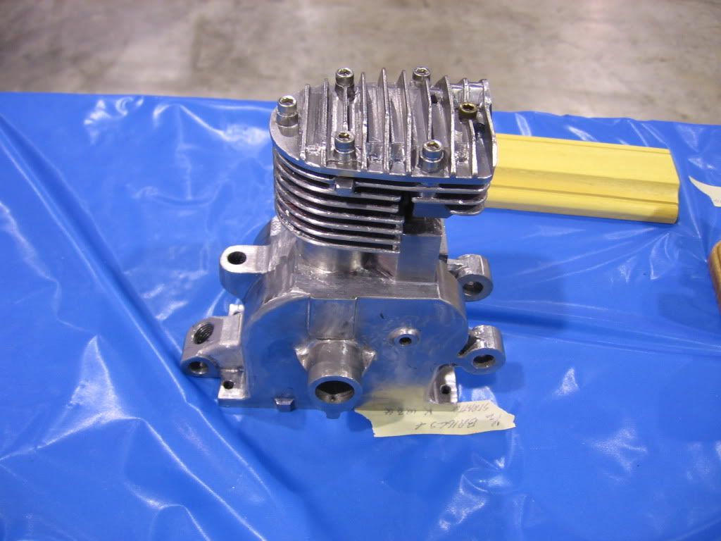
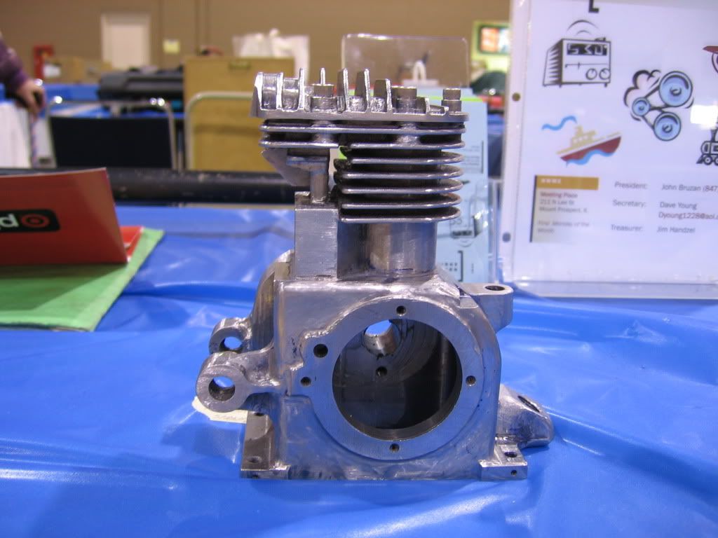
Gbrit....in the original the cylinder and crankcase are all one casting. I hope to do the same though it will be machined out of aluminum...hence the cast iron cylinder liner. That is going to be a challenge to say the least and i keep looking at the crankcase/cylinder and hoping for some epiphany as to doing it. I think it will take some degree of fabricating combined with machinig.

I have a few progress pictures I will post below on the liner, one smaller brass plate, and the cylinder head.

Regards,

Bill
 
one of the first parts I drew was the thin curved sheet metal piece that wraps around the cylinder fins and to which the engines name plate was attached. Shown below is the drawing itself glued to a piece of .015 brass. 3M makes a spray adhesive which works very well for this and can be later cleaned off with thinner. As can be seen the top section still need to be cut/sanded/filed to the lines of the drawing, then the mounting tab will be bent, and once the cylinder is finished the brass will be curved to fit it.


IMGP1103.JPG
 
A little progress on the cylinder liner, but i admit this was drilled out to 7/8" on the bigger 13 x 40 lathe at work. The final 1/8" will be bored on the Sherline and then honed to final size.


IMGP1104.JPG


IMGP1105.JPG
 
I have begun drawing the rather irregular shaped cylinder head with its various angles and radiused curves. One method I have found helpful is to measure and sketch as closely as possibly the overall outline of the part at half scale which is the scale of the model itself. Then print the outline at 2:1, or the size of the full size engine part which can then be placed on the drawing for comparison. So far this has worked for the main engine shroud (sorry no pics of that) and most recently for the cylinder head, shown below. The same procedure was used after these pics and after the addition of the bolt holes in the cylinder head drawing.


IMGP1106.JPG


IMGP1107.JPG
 
Good progress, that head looks awkward, well impossible to me but can't wait to see it emerge!

Nick
 
Thanks Nick. The head shouldn't be too bad, though the underside (not pictured yet) may be the hardest part. As you can tell I am working on the various parts which will connect the the crankcase first. That way it will be easier I hope to transfer the hole patterns to the drawing of the crankcase. This engine would be an ideal one for a set of castings, just wish i had the skills and equipment to pursue that.

At any rate, back to finishing the cylinder liner for now, then the piston rings and getting that all to fit. The next two items will be the connecting rod and the cylinder head.
 
Hi Bill
Only just found this post, don't know how i missed it.took a while to read
it all but I'm glad i did. really really looking forward to the rest of the build.
This is one post I'm going to bookmark.
You are doing a fantastic job, hope the the rest of the build goes well for
you.
Ken
 
Thanks Ken,

I wish it were going faster but the day job keeps getting in the way...lol. Still making some slow but steady progress however.

Bill
 
Hi Bill,

Great work, the air cleaner and starter cup look fine. Last year at NAMES a fellow across from our table had a B&S well under way. I think it is half scale and in steel (wow!). Unfortunately I didn't get his name but I thought you might like to see a couple of photos. The Briggs and Stratton 5 and 6S's have always been a favorite of mine. I have a 5S and would like to follow in your foot steps someday. I can see no big problem in modeling one of these, except of course, the magneto. Keep up the great work, I will be anxiously watching the build.

023.jpg


022.jpg


Chris
 
WOW is right! That is a beautiful modeling of a Briggs Model Y block.
I have restored a couple of them.

1935%20Model%20Y%20%20Done%20Front%20with%20Starter%20Cover.jpg


Did you happen top ask him how he made the fins in the cylinder area of
the block? Have you come up with any thoughts on how to approach that Bill?

Rick
 
Hello everyone,

Unfortunately, Rick, I never got a chance to talk to the fellow. Hopefully he will be at NAMES in April and I will be sure and talk to him and get some photos.

Chris
 
Thanks for the pics Chris. The block will be the most intricate part and I hope I can do as much justice to it as that fellow has. Thanks for the full size pic too Rick.

Not to disappoint you Chris, but I am planning on using a Hall effect sensor and coil for the ignition. My thinking is that it will be more fool proof but that's still down the road a ways. I have thought of including "dummy" components (condenser, points, etc) just for looks, though with the engine shroud on they would never be seen. Choices, choices... :-\
 
Rick, I just noticed your question as to the fins. The 6S would seem to be a little easier than this y block in that there is not a finned passageway between the cylinder and the area where the valve stems come up from the crankcase. There is some contour to the fin outline meaning varying depths as it traces the periphery of the cylinder, but I still think this can be done with a slitting/slotting saw and rotart table set-up. Would be ideal for CNC but since I will be doing it manually, I will just have to work out the various depths as the crankcase/cylinder is rotated around. What worries me far more is the part of the crankcase which houses the larger gear driving the cams. I will try to take some pics tonight to illustrate both of these points.

Bill
 
Bill,
I just picked up this work in progress and read all the posts on your project. Your work is beautiful and the pictures are great. Thanks for your efforts in sharing your work with us. :bow:

Cheers,
Phil
 
Thanks Phil for the comments and for looking at the thread. I took a few pictures of the full size crankcase tonight just for comparison to the y block crankcase shown. The fins still look a little easier than on the y block, but how to make the rounded "bulge" which houses the larger cam gear has me scratching my head This is one of those cases where i just keep staring at it and eventually something will dawn on me. Fortunately I have plenty of other parts to make until that happens.

IMGP1110.JPG


IMGP1111.JPG


IMGP1112.JPG


IMGP1113.JPG
 
Bill I apologize for my constant breaking in on your build here, but being
a Briggs collector I can't help myself. :-[

Was there anything on that pin that is sticking out of the back of that crankcase?
The 6S is rarer than the 5S. Lever and Kick Start models are even rarer!

This is a Lever Start 5S that I bought for $25 as a basket case on a 1951 Eclipse Rocket
reel mower.

Rocket%20Mower%20Blower%20Starter%20Side.jpg


After a total restoration of the engine and the mower it would start on the first
pull and even cut grass!

[ame]http://www.youtube.com/watch?v=HFtplyxQfRw[/ame]

I ended up selling that restored mower at auction for a tidy profit.

I appoligize again for my drifting here but the lever start engines are quite rare
and I can see no other reason for that pin being where it is. It's kind of exciting to
see from a collectors point of view.

Rick

 
Rick,
Please don't apologize...your contributions have been invaluable certainly to me and I think to the thread also...so as the HMEM guru on Briggs, by all means keep the comments and observations coming. As I noted at the outset, this engine was also a basket case I picked up at our old engine club's swap meet for 20-25 dollars mainly because I liked the lines of it and it had most of the parts intact....less the gas tank, carb, and air filter as you already know.

As to your question, I wondered what that thingy was for myself...there was nothing attached to it when i bought the engine. I had assumed it may be some sort of motor mount though I have no idea what the engine had previously been used on. The "thingy," whatever it is is on the pulley side of the crankcase and the opposite side had the conventional starter hub for a rope pull. Is it possible that any of these engines could have had both a rope start AND a kick start?

As to the model...I got that off of the nameplate...and earlier you had helped me determine the manufacturing date based on the flywheel markings. If it would help to know the serial number I think I can still make it out on the nameplate. Sorry I can't be of more help here but again, please don't be shy about chiming in at anytime. I would love to know as much as i can about this little guy.

Bill


The flywheel marking indicate the date that flywheel was cast.
The serial number would give the units manufacture date. They are
usually pretty close. This is the serial number chart for the 6S.
The number in each box shows the last unit manufactured that month.

Briggs6SManufactureDates.jpg


Rick
 
Rick,
As the photo shows, the serial number is 248954 which would put the engine mfg. date in Feb of 1951. Although it doesn.t show unless you blow the photo up it is indeed a model 6S. Maybe the type #701054 gives some additional information that you would know about. Now you have me very curious as to what thet thingy is sticking out on the pulley side of the crankcase ???

Bill

IMGP1109.JPG
 
There just may be an answer to that in the Type Number.
I don't know the code to the Type Numbers, but Briggs might.
I have already sent off an email to them, we'll see what they
come up with. They are usually as helpful and they can be when
it involves their antique engines.

While I was searching my archives to see if I had that number code list
I found a couple of old Briggs photos that I had forgotten about.

1919 to 1924.
Fourth floor of the Wheel Motor Plant.

BriggsPlant1924.jpg


Briggs Plant during WW1.
These Gals are actually making grenade housings.
A single cylinder engine with one heck of a power output!

BriggsPlantWW1.jpg

Those snazzy jumpsuits were issued by the Defense Department because
the felt the Victorian dresses of the day would be too dangerous in a machine
shop.

OK, I'm drifting again...
We'll see what Briggs come up with on the Type Number.

Rick
 
Back
Top