Brian's Donkey Engine

Home Model Engine Machinist Forum

Help Support Home Model Engine Machinist Forum:

This site may earn a commission from merchant affiliate links, including eBay, Amazon, and others.

Brian Rupnow

Design Engineer
Project of the Month Winner
Joined
May 23, 2008
Messages
14,969
Reaction score
8,250
Location
Barrie, Ontario, Canada
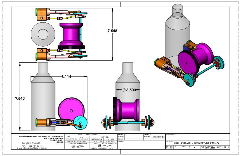
I followed Captain Jerrys Donkey Engine post with great fascination, until alas, it kind of bogged down and came to a stop. Now that I have the capability to cut spur gears, I have been searching thru all of the Youtube postings of Steam Donkey engines, and decided that there are many different types and configurations of said engine. I think I would like to try building one myself, and of course I will post build drawings as I go along so that others may join in the fun if they wish. I don't have any experience with donkey engines, and I don't have one close at hand to run out and measure, but that probably isn't as large an issue as one would think. I have found a youtube video which I will post a link to, and it shows the one I may try to design/model/build. This much I understand---there is a double acting cylinder on each side. The crankshaft is actually a long pinion-shaft that reaches from side to side, and since the engine would have to be self starting, the crank throws will have to be 90 degrees out of phase. I know that the pinion and the very large gear are constantly in mesh, and that the big gear is fixed to the large winch shaft so that the winch shaft turns whenever the engine is turning. The winch itself is supported by bearings which "float" on the main winch shaft, and there is a clutch mechanism (which is explained very well in captain Gerrys article) that transmits torque from the main shaft to the winch drum. This clutch mechanism is operated by a manually engaged lever.---I think the lever and clutch mechanism only has to be at one end of the winch drum. I can't see any good reason that this engine would ever have to go into reverse, because when cable is pulled off the winch drum, the drum can "free-wheel" to play out the cable. Some of this type of Donkey engine was used in mine hoists, and consequently had a large ratchet and paul assembly, but I don't think that was needed on a Donkey that winched logs across the ground. Also, Jerry makes reference to an external band brake which gave him difficulty, and I'm kind of wondering why it was there. To the best of my knowledge, this type of winch only pulled, as you can not push with a wire cable. why then have a brake on it at all? I welcome all discussion, as I'm just getting my head into this thing now. I am not trying to steal any of Captain Gerrys thunder, as his post and machine are excellently done, and mine will be somwhat different. Comments and helpfull hints or theories please.----Brian Rupnow
[ame]http://www.youtube.com/watch?v=VM3qRcWmo-4&feature=player_embedded[/ame]
 
Hi Brian,

Looking forward to seeing this come together. The reason for a brake is if you are using it as a hoist you want to be able to hold or lower the load without it crashing down or dragging something up a hill you don't want to give up your hard-fought ground and have it slide back down.

I would suggest the books "In Search Of Steam Donkeys" by Merv Johnson and the reprint of the Willamette Iron and Steel Works 1925 product catalog. They are full of pictures and drawings and cutaway views of Pacific Northwest logging donkeys. Neither one is cheap ($60 or $70 I think) but very interesting. The WISW catalog has parts diagrams of clutches and brakes. If I find someone with a scanner I'll send some pages to you.
 
Jared---that would be greatly appreciated. I have completely "blown my budget" in the last two weeks, purchasing a set of involute gear cutters, a broaching set, an arbor press, two sets of 1-2-3 blocks, and an Ivan Laws book on Gear cutting!!---Brian
 
Brian,
Most donkeys had at least 2 drums. They were used to yard or move loads from one point to another point. A single cable can only lift the load in a vertical direction with two cables the load can be lifted and moved. The rigging gets complex and I am not an expert on this type of rigging. Brake drums keep the drum not being powered locked so the haul back line does not go slack and the load moves in a controlled manor.

The Willamette yarders had either Stephenson or Marshall reverse gear.

Dan
 
They usually have multiple drums with different size cables on them depending on whether they were hoisting or yarding. I helped restore a 3 drum Willamette a few years back. The smallest cable was known as the haywire or straw line drum. It was drug out by hand into the brush, thru a block attached to a stump or other anchor point, and led back to the engine. The light line was then used to pull the much heavier mainline out. This was then hooked to the anchor and the donkey was dragged farther out into the wood. it was quite a job pulling them out 500 yards at a time, and you can see why many of them were abandoned in the woods once the job was over. I know of 2 in the wild here in the northwest, and they are both at least 5 miles in from the nearest road, so recover would be a very expensive proposition.
 
I have been setting here eyeing all of my models, and I keep going back to the Popcorn engine. It is such a smooth runner, and I already have it modelled and detailed. With a bore of 1/2" and a stroke of approximately 1" it is close to the right size. There is a potload of work in that crosshead guide, but it does work so well-----. I really like the shape of the cylinder, and it would be very easy to complete in right and left hand versions to make up a twin cylinder engine. I think I will stick with the single drum version, as per the video posted in my very first post, with an internal expanding clutch ala Captain Jerry, and an external band brake courtesy of yours truly. The flywheels would become much smaller, in fact virtually dissapear, but thats not such a big deal with a twin cylinder double acting engine with the crank throws offset 90 degrees. When I built the Popcorn engine, I was workingf from Stews early plans and converting them to British Imperial, however I got ahead of myself and forgot to "unmetricize" the crank throw, making for an very unususl stroke length of 0.984". If I use that engine as the basis for my Donkey, it would give me a chance to correct that.
 
Brian

This will be interesting, to you and the rest of us watching. I watched the video that you linked to and it is a simple looking machine. Its not clear how this particular one was used but it helps illustrate some of the history of these machines. I don't know who the manufacturer was but they all had a lot in common.

They were offered in the bare base model as this appears to be. Two cylinders, pinion shaft with cranks, and a drum. From there you could add components to suit the application. Even though this one does not seem to include drum controls, the drum is a standard casting that includes a clutch/brake drum with ratchet teeth. I don't see any hand control levers or foot pedals so it seems that the hoist drum is fixed on the shaft.

The pawls for the ratchet would seem to be a simple thing to add but it some applications, they could be a nuisance or a hazard.

Internal clutches with hardwood friction blocks engage or disengage the drum from the shaft but were not used the way we use a clutch with a diesel engine. They were "slipped" rarely if ever. The engine was stopped or slowed and the clutch was fully engaged before the engine speed was increased. The clutch might be slipped to take the slack out of the cable but one the load was encountered, the clutch was fully engaged and the load controlled with the engine. Unlike a diesel, a steam engine has full torque at low speed and does not stall in the same way that a diesel does.

A load can be lowered with brakes (usually foot controlled) but could also be lowered by slowing the engine and slipping the clutch. Brakes make it a lot easier, particularly with two or more drums.

By not modeling a particular machine, you will leave yourself a lot of leeway. Add or leave out some feature and you will still be historically accurate. Somebody, somewhere, specified one just like it. Just keep it in the flavor of the time and you will end up with an attractive model.

I'm in for the ride.

Jerry
 
Thanks Jerry. ---I was hoping that you wouldn't be upset that I was contemplating making one of these models. I was fascinated by the progress you had made with yours. I am going to put a clutch on the one I build, similar to what you used, and I think I will probably design a manual band brake. As you did, I will also include a "boiler" that although not actually used will lend an air of "Authenticity" to the model.
 
Scale and proportion---Where do I start? Well, the stroke of my engine is going to be 1", so the crank throw will be 1/2". If you look at the "flywheel" end of the connecting rod in the video, you will see that where it connects to the "flywheel" is about 1/2 way between the center and the outside of the rim. That would make the "flywheel" 2" in diameter. The main large gear appears to be about twice the diameter of the flywheel, so that would make it 3 1/2" to 4" in diameter.The length of my cylinder is fixed, to accomodate the 1" of piston travel, and the distance from the end of the cylinder out to the end of the piston rod at full stroke is now established by the length of cylinder and the stroke. In the attached picture, there is only a slight gap between the front of the boiler and the flange of the drum, which is roughly the same diameter as the large gear. The center of the cylinder is just marginally on the far side of the boiler centerline. The position of the crankshaft relative to the position of the large gear wheel and winch will be established by the pitch diameters of the large gear and the much smaller pinion gear on the crankshaft which engages with it. In both the video and the attached picture, the boiler diameter is equal to or slightly smaller than the diameter of the large winch gear, which makes it roughly 3 1/2" in diameter. The overall width of things will be established by how tightly I can fit the cylinders and valve bodies to the sides of the boiler. That gives me enough information to start laying out the components. I will make a preliminary layout, then compare it to pictures and videos of old existing full size Donkey engines, and move things around until get a good visual match. Thats how i start a project like this.
AUDELS-G2-HOISTS-07.jpg
 
Brian

Not upset at all. I am surprised that more people have not built one of these fascinating machines! They are a great part of North American history. Logging, mining, shipping, and any type of material handling adopted these versatile tools. They were the antecedent of the donkey but they were the predecessor of every cable operated crane, shovel, dragline, clamshell, up to the introduction of modern hydraulics.

The construction site of the World Trade Towers (visible on Google Earth) is dominated by a Manitowoc Crawler Tower Crane. If you were to rip off the sheet metal, the parentage of this huge machine would be obvious. Three horizontal drums, each mounted slightly higher than the one in front of it, with internal expanding clutch, and external brake band. There are additional smaller drums on this machine for boom/jib control and swing but the layout is strikingly similar. I spent a lot of my life in the mining and construction machinery business. I love these machines.

Please feel free to adopt or modify any of the methods that I posted in my temporarily dormant donkey build. That is what this forum is all about. Maybe if you design and post a satisfactory solution to the brake band, it will prompt me to revive my project.

Brian Rupnow said:
Scale and proportion---Where do I start?

You will always wish that you had gone bigger! That is about the scale that I used and I found myself dealing with (PITA) #0-80 fasteners. (PITA) to stay in scale. I had one of those double lens jewelers magnifier attached to my glasses. If I haven't already said so, they were a Pain In The A..., oh, I already said that.

Jerry
 
Maybe if you design and post a satisfactory solution to the brake band, it will prompt me to revive my project.

'Imitate the actions of the ....' dept Jerry - have a good study of the kickback brake on a chainsaw!

Interesting project Brian - reviving my interest in doing one.
 
So tell me guys---In the units with more than one winch drum, does each drum have its own individual brake and clutch mechanism?
 
Brian

The answer is "yes". The pinion gear engages both big drum shaft gears so both drum shafts are turning anytime that the engine is running. Either or both of the rope drums can be engaged by the operator. A lot of skill and coordination required.

Jerry
 
The other way you can do it is to have the pinion driving one drum and the other drum driving off the first one. This causes them to turn opposite directions so then you wind the line on the top of the back drum and the bottom of the front. Another variable that you can play with is the gearing and drum core diameters. Most yarding donkeys used in logging had the back drum (mainline) geared so it turned slower and pulled harder than the front drum, which was geared faster and had a larger diameter core for speed since all it had to do was return the rigging to the guys in the brush.

te_gui said:
I helped restore a 3 drum Willamette a few years back.

te_gui, where's that yarder at? Is it in running condition?
 
Okay guys---This is sorta, kinda, it. Overall proportions are going to be very close to this. Length of winch drum may grow a little, and I definitly have to come up with a main base. I will probably come up with some other kind of crosshead guide, but the jury is out on that for right now. Thats a 90 tooth gear on there, which works out to about 3.83" diameter. Overall, I don't think it looks too bad.---Brian
FULLASSEMBLYDONKEY-DRAWING.jpg
 
Brian-

You won't be able to adjust the valve stem very easily with those steam chests turned towards the inside.

Pat J

Edit:

I am looking at the old engravings, maybe that was how they did it.

Edit 02:

For some reason, I thought I remembered the steam chests facing out in the old engines, but they do not. The steam chests on the old engines are further forward on the frame than your design, so that the steam chest covers can be removed without removing the boiler.
 
I thought that as well, maybe move the drum forward of the crank and then the boiler can be moved towards the crank and the valve chests will then be behind the boiler.

J
 
Brian

That looks good. You might think about reducing the drum spool diameter and making the flanges straight sided. Drum capacity was a factor where the log haul was very long. Wooden lagging staves could be added to the drum to increase the line speed if desired. Straight flanges make that easier. The flanges were usually pierced with bolt holes to make adding and replacing the lagging easier.

I like the looks of the X-head guide and there is historic precedence for it. I just can't remember which maker used that style.

Jerry
 
Back
Top