Brian does Ridders flame eater

Home Model Engine Machinist Forum

Help Support Home Model Engine Machinist Forum:

This site may earn a commission from merchant affiliate links, including eBay, Amazon, and others.
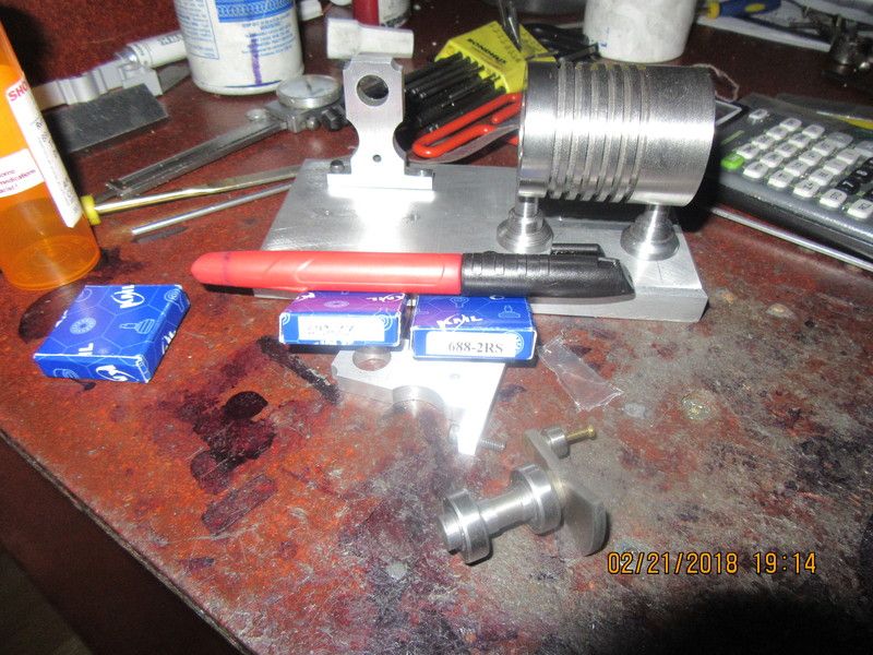
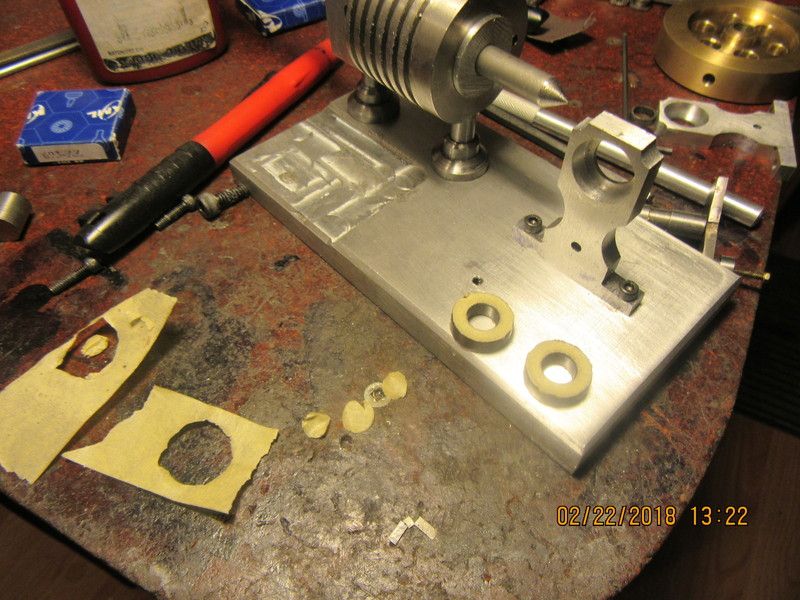
My three bearings came in today. They cost $23.00 total and have seals on them. I'm not going to rush to take the seals out at least until I am set up to do some comparative tests to see how easily they spin. The key issue is that they fit the crankshaft and con rod pin properly. Tomorrow I will put the counterbores in the bearing supports and maybe build a con rod. I am still a bit undecided what material to use for pistons. Jan Ridders drawings indicate that you can use graphite OR cast iron. Nobody in Barrie sells machinable graphite, and I already have some cast iron left over from other projects. I may go with cast iron and if it don't work I can switch to machinable graphite after the fact.
WzkQar.jpg
 
You will be amazed how much drag there is in those sealed bearings Brian, both from the seal lips dragging on the inner race and the (much higher) drag of the grease. If you want to retain the look of sealed bearings, along with a bit of protection from dust, etc. shielded bearings are the way to go as they don't contact the inner race with the shields. You will still have to wash the grease out though.
 
...I am still a bit undecided what material to use for pistons. Jan Ridders drawings indicate that you can use graphite OR cast iron. Nobody in Barrie sells machinable graphite, and I already have some cast iron left over from other projects. I may go with cast iron and if it don't work I can switch to machinable graphite after the fact.

For what it's worth, the main difference I see is that the cast iron is harder than the aluminum and might wear it out, while the graphite wouldn't. But I'd probably use the cast iron, since I had it.

I don't know how much it matters.

The Duclos engine I'm building says bronze, or cold rolled steel for the piston (also with an aluminum cylinder) and I'm trying the CRS.
 
i thought his cylinder was SS not aluminum? or is there an aluminum part that rides on the pistons?

also Brian, you may have already mentioned. but will you be honing the cylinder or laping it?

looking good so far.
 
The cylinder is 316 stainless steel. The cylinder was drilled, then reamed with a 7/8" reamer, then honed with a 3 stone brake cylinder hone held in my variable speed drill at about 1/3 of full speed and passed from one end of the cylinder to the other 100 times, coming about 1/8" out of the cylinder with the honing stones each time on each stroke. The lapping part will happen when I make the pistons. I turn them to about 0.0005 oversize, then lap them into the cylinder with 600 grit lapping paste until the pistons just press in with light finger pressure but won't fall thru.
 
Okay--The bearing stands are counterbored and the bearings (complete with seals and full of factory grease) , crankshaft, and flywheel are installed. Time for some comparative testing. This is hillbilly work at its finest. Using an online stop-watch, I gave the flywheel a spin and started then stopped the stopwatch. I repeated this 5 times. The average length of spin comes out to 7.18 seconds from when I flicked the flywheel into motion until all motion stopped. Next step will be to remove the seals, wash out any factory grease, then reassemble and check the "free-wheeling" time again.
 
The results are in, and they are incredible. I disassembled everything, pulled the seals out of the bearings, then washed them in laquer thinners and blew them clean with compressed air, then reassembled everything exactly as it had been with the previous test. I did five runs, using the same finger pressure to spin the flywheel (That is the hillbilly element) and the average length of free-wheeling was 2.51 minutes. That means that on average, the bearings without grease will spin 21 times longer than bearings with grease.
 
As this assembly continues, I thought I might have an alignment issue with the centerline of the cylinder and the center of the very small ball bearing on the end of the crank throw. So--I made myself a special weapon, and installed it. I was right. The tip of that special weapon should fall directly on the center of the bearing.---It doesn't. Now I have to figure out what I'm going to do about it. I don't want an offset in my connecting rod!!!
NDLpQ2.jpg

bWpZ5o.jpg
 
Hahh!!!--It was the old "slot the bolt holes and move the cylinder over a bit" trick that saved the day.-I have to declare now--This was not a fault with my drawings. It was more a testament to accumulated tolerances and my inability to position everything dead nuts accurately when machining. Anyway--We're good now. The point of the new weapon is on center of the small bearing.
JTPT6Z.jpg
 
Here's a little trick your mother probably never told you about. When you locate a bearing into a prepared pocket that is "size on size", the bearings lose all ability to "self align" with each other. This can cause binding and make the shaft reluctant to spin freely. If you make the pocket about .001 to .002" oversize, then use a bit of Loctite on the outer race before assembling things, this lets the bearings align with the shaft and with each other. The trick though, is to not get any Loctite down into the balls of the bearing. So---as you see, I use masking tape and a scalpel to make a temporary "shield" on both sides of the bearing to keep Loctite out. Add my Loctite, reassemble everything quickly, tighten the bolts and let it set for 24 hours. The bearings will be perfectly aligned, and you can then safely disassemble things and remove the tape from the exposed side of the bearing. On the other side of the bearing that becomes inaccessible, just leave the tape there. It won't hurt anything.
n50ThB.jpg
 
Brian, do you plan to put a brass or bronze bushing or sleeve in the push rod guide hole drilled the length of the cylinder? would having a short one on both sides help reduce friction for the pushrod?

also, curious did you drill the guide hole before cutting the cooling fins or boring the cylinder hole? edited, sorry I see that you drilled the hole afterwards
 
Last edited:
No guide in the pushrod hole. It is not a reamed hole. Only drilled, which makes it .001 to 0.003" oversize. The pushrod is 0.005 undersize.
 
Today I managed a con rod. It wasn't easy and it isn't pretty. Actually this is the second attempt. The first attempt--I don't want to talk about it. The bearing was only available with shields, which made it 5 mm wide rather than the 3 mm that I expected. This lead me to making a con-rod .094" thick with a 5 mm wide (0.197") hub. I am going to attach the bearing to the con-rod with a dab of Loctite. Right now it's a slid-in fit.
3t9r2p.jpg
 
Brian, can you see any reason the bearing standards cannot have through holes instead of pocket? This would allow the standards to be bolted to the base plate and line drilled and reamed in place.
Ray M
 
Yesterday afternoon I decided to buy a 12" length of cast iron to make pistons from. I do have lots of short pieces in my stock drawer that would have each been good to make one piston, but this cylinder is kind of a special case, because the internal valve and the piston must both be lapped fits. Since both the internal valve and the piston would both have to be exactly the same diameter, I decided that this was the best way to do it. My cylinder is about 2" long. I turned a length of cast iron down for a length of 2 1/2" to a point where it would just start into the cylinder but not slide in. Then I coated the machined area with 600 grit carborundum paste and very carefully with the lathe running at its lowest speed, I manually worked the cylinder onto the rotating cast iron. This is very dangerous, and you want to be prepared to immediately let go of the cylinder if it "grabs" and starts to turn with the cast iron. By letting the 2" long cylinder move to the very limit of the turned cast iron and then sliding it back and forth, this resulted in the full length of the bore being lapped to size, and guarantees that the parted off pistons from the cast iron will be lapped to the correct outer diameter.
lzbVN4.jpg

UAG4VA.jpg
 
Back
Top