Brian builds a Corliss

Home Model Engine Machinist Forum

Help Support Home Model Engine Machinist Forum:

This site may earn a commission from merchant affiliate links, including eBay, Amazon, and others.
The Improved Greene is like a Corliss but has a different mechanism for the exhaust valves. I would like to find plans for it, but cannot find any. I have seen a coulple builds but that is all.

Richard, read the last few posts where Jeff said he can supply the plans (pdf) for the engine over on MEM
 
Now it's time for me to take on opinion pole!!---The cylinder for this critter is 2 1/8" square x 2 1/2" long. I have a piece of aluminum here that is bought and paid for, but as I understand things, aluminum has a high coefficient of friction, which I'd like to avoid. Mild steel would work all right, because I will be running on compressed air, not steam. Only thing is, there are a ton of #4-40 and #5-40 tapped holes in this thing, and a very real chance of breaking a tap. I find that cast iron is easier to tap, but a phone call to my metal supplier this morning tells me it will cost $30 for a piece of 3" diameter cast iron x 3" long. What material do you recommend that I use?
 
Now it's time for me to take on opinion pole!!---The cylinder for this critter is 2 1/8" square x 2 1/2" long. I have a piece of aluminum here that is bought and paid for, but as I understand things, aluminum has a high coefficient of friction, which I'd like to avoid. Mild steel would work all right, because I will be running on compressed air, not steam. Only thing is, there are a ton of #4-40 and #5-40 tapped holes in this thing, and a very real chance of breaking a tap. I find that cast iron is easier to tap, but a phone call to my metal supplier this morning tells me it will cost $30 for a piece of 3" diameter cast iron x 3" long. What material do you recommend that I use?
30$ for 3" diam by 3" long is not a terrible price. How long do you need total? And what do you mean by 2-1/8? is the the diameter or the total area of the piston? YOu say "square' do you mean diameter?
 
Richard, why not look at the images on the first page of the thread you will see that the cylinder is a six sided block 2.125 x 2.125 x 2,5 long. Brian will just be able to get this out of a 3" diameter round bar which is quite a common way to do it as round bar is easier to obtain.

regarding the Greene, read the replies just after your post here Greene Automatic Cutoff Steam Engine
 
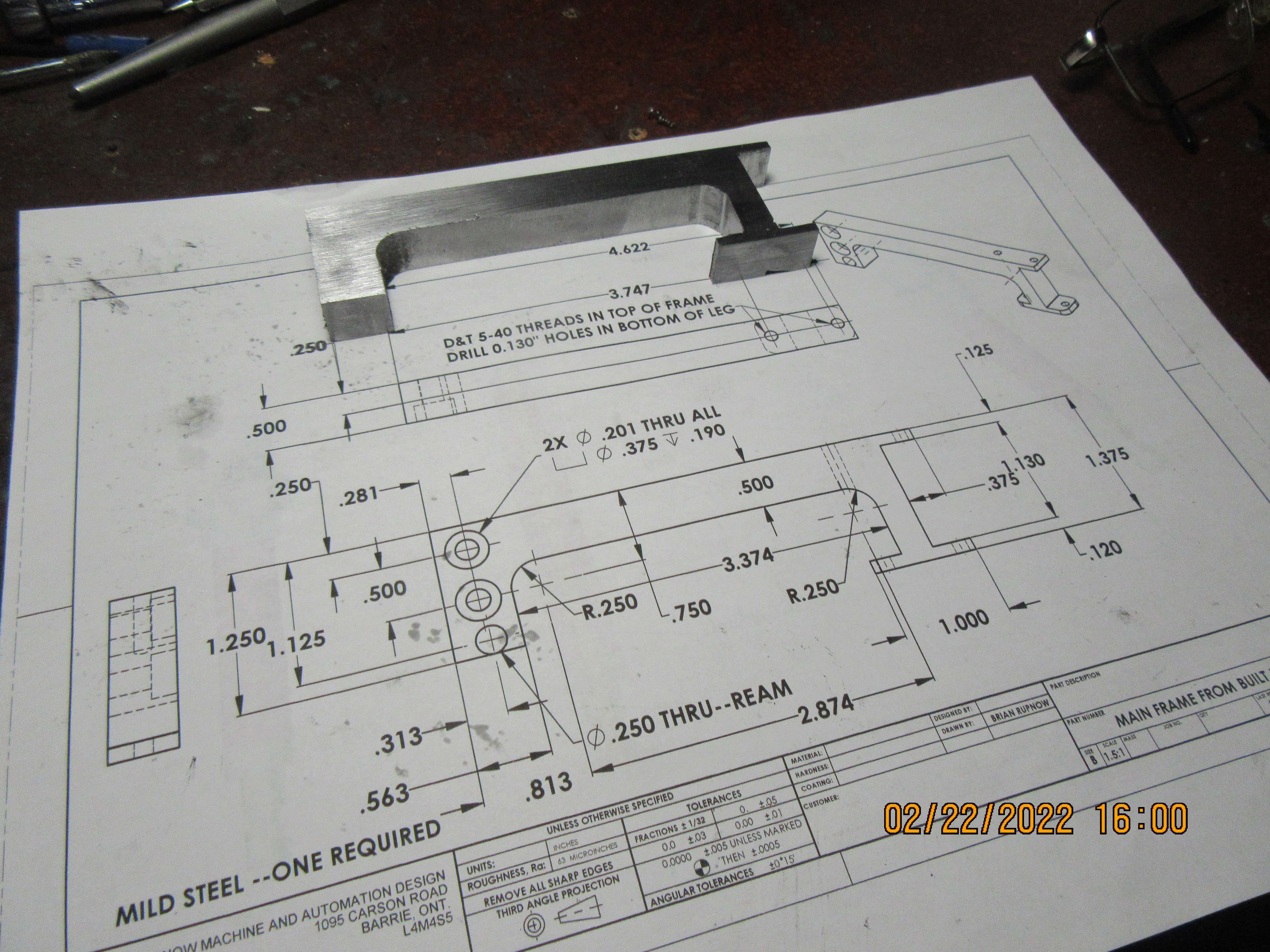
Sing Hallelujah baby---we got the first part made!!! It still needs a bit of fettling and a few holes, but I'm off to see a man about a flywheel.
LvZVjH.jpg
 
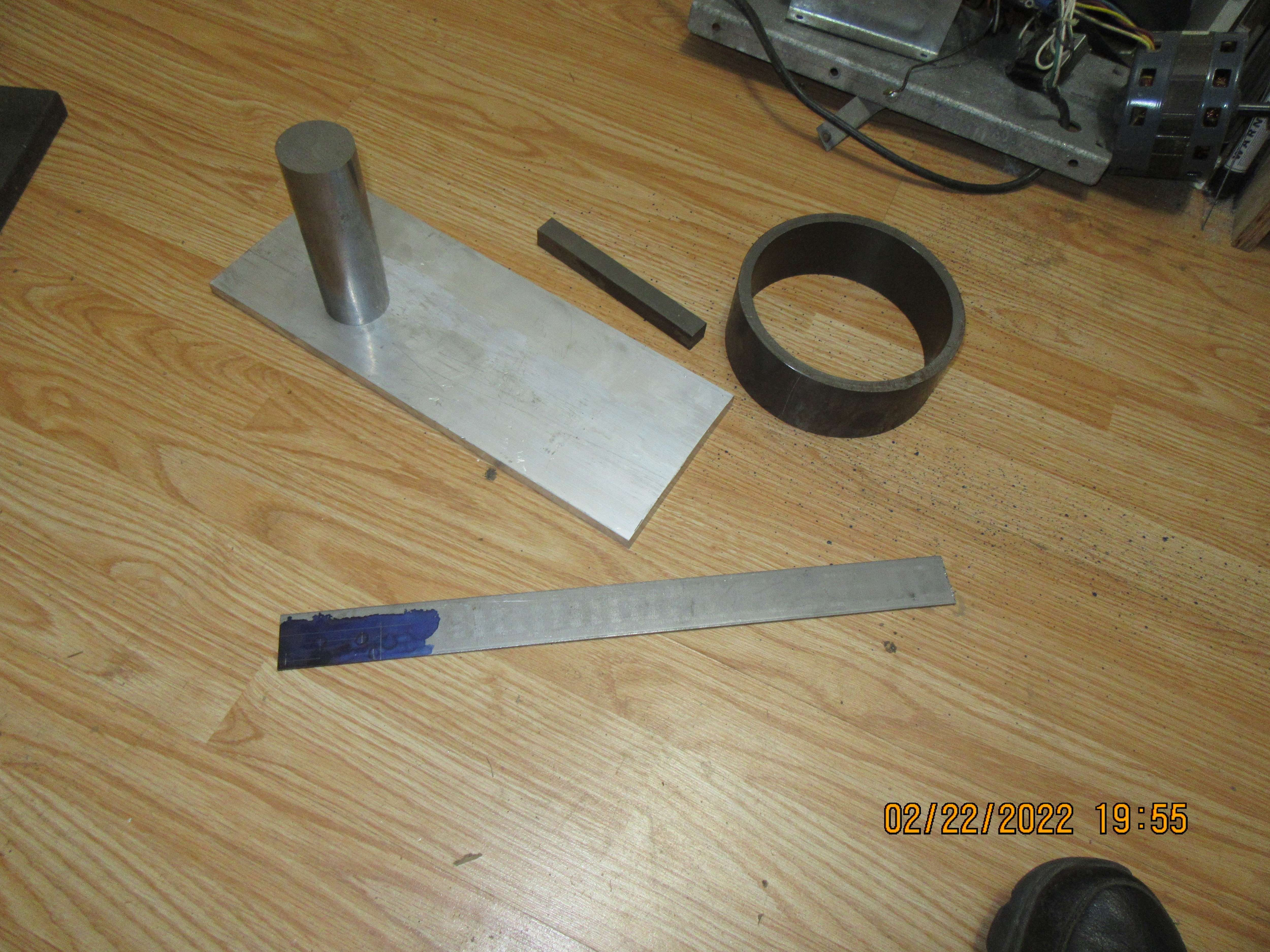
I drove across town to my metal supplier and gave up $55 of the Rupnow Fortune for material. The flywheel as it sets is 7" o.d. x 3/8" wall thickness, which is close enough for me. The 6" x 1/2" aluminum is going to be the main baseplate, the 2" round cold rolled is going to become the cross-head guide, and the rest of the stuff is to make "feet" that holds the cylinder up.
q4EiBD.jpg
 
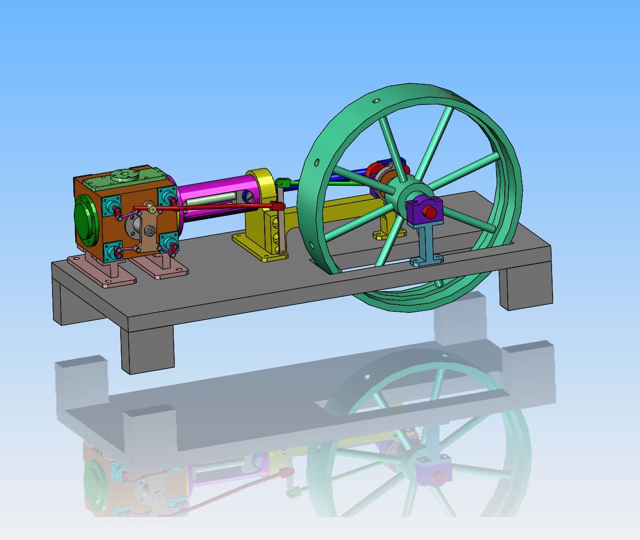
I have changed the solid model to show the piece of 7" outside diameter pipe as a flywheel rim. I'm not going to show all of the notches around the flywheel rim, as they serve no purpose here and are not needed. I'm not 100% sure how to attach the spokes to the outer rim, but right now I'm thinking that if I can hold everything concentric I may make the spokes 0.100" too short and fill up the ends at the flywheel rim with tig weld. This will serve to hold the spokes in place and if I overfill the holes and then take a clean up pass on the outside diameter it should look okay.
68Fus0.jpg
If your spokes are the same size as the hole, you can make them to the right size then weld thim in place doing a clea up pass on the welds. just use careful cutting on welds--not necessarily a goo idea
 
I was wondering what those notches or teeth were for. I looked at the videos you posted yesterday (?) and couldn't see any reason for them, either.
The notches on the outer edge of the flywheel are for "barring" the engine which is manually rotating the flywheel to set the valve timing for starting. They used large crowbars and later used smaller engines for barring.
 
Brian, this will be an exciting build for me to see, I run one when I was a little fellow, I was told keep the boiler full and all the oil drips full, it was installed in 1895 at an Irrigation company in south Louisiana that pumped water for the Bayou raising it 26 feet to the irrigation canal that went for four miles to another crude oil engine that raised the water 15 feet, I would spend a lot time there with the old men and they taught me a lot, so I probably 13 running the 11-7 shift, I thought I was good till one night it started pounding like the floor was going to break, went around the valve side and on to the square bushing had a worn edge and that dashpot would drip the valve early, I stood there for four hours lifting it so it could close, little kid did not know where others were to replace, guess I did not learn a lot after all, the old fellow came to take my place at 7 AM and stat on a bucket and rolled his cigarette, started smoking, not looking to the kid, I let that valve drop then he coming running, go a fresh on screwed it and run perfect, the flywheel was in two halves, Hughe nuts on the shaft and the outer ring had several nuts on the inside, I had one rope that was three inch diameter it was continues from one pulley to the other, sure I figure it out even learned how to weave rope, then in 1974 big boss steam out in went a Wakesha, with two jack stands, would not pump as slow nor as fast, we were stuck it, the original was fired by wood, that is all the did cut and split wood for the boilers, they worked year around, then they discovered oil in 1901, switch to burring crude oil then later switch it to natural gas, that got the boiler up quick, I will try to get some photos together, I would love purchase some plans of that, that would bring back a lot of fine remembering , sill love the smell of steam and oil, would you consider selling me a print
 
Lathe Nut--When I am finished and the engine runs, then yes, I will sell a complete set of my drawings for $25 Canadian funds. You must realize though, you are not buying an original design. You will be buying my drawings of my interpretation of someone else's design.
 
Just for info, the complicated arrangement that allows variable and rapid closure of the inlet valves, is called 'trip gear'.
The valve is (usually) closed by a spring, and the dashpot arrests the motion so that the valve does not slam against the stop.

Some videos showing different configurations in operation:

This is an interesting technical demo of the Corliss valve gear from the New England Wireless and Steam Museum:


If you look around their youtube channel or website site, you will find a number of other videos about that particular engine, which is believed to be the only original Corliss company Corliss engine that is still able to run under steam power. They fire it up for demos at least once per year. I have been there for that, it's an impressive thing to see.
 
Brian, yes, I do understand that, and I have not seen any drawing of one but guess I was not looking with understanding, would like your instead, thanks, will follow along and keep quiet, thanks again, Joe
 
Hi Brian: Post #23: I reckon you should invest in a lump of good quality cast iron. Your engines will outlast you, as I have an engine made by apprentices in the 1930s, at the local college. My Great Grandfather's Engineering works had a coal truck (scale model ) that they used for Sales purposes in the 1880s - accurate and working - 4 3/4" gauge - that I inherited, but had to let go in the 1970s - when it was about 90 years old... Most of the best models have found a home with "curators" decades after the makers have past. A testament to the quality of their their maker's workmanship and expertise. So the cast iron will be a good investment.
On that note,
Enjoy the kids' inheritance now!!
K2
 
Back
Top