Bore stroke ratio

Home Model Engine Machinist Forum

Help Support Home Model Engine Machinist Forum:

This site may earn a commission from merchant affiliate links, including eBay, Amazon, and others.
I had looked at a few plans before designing my own open crank hit and miss engine and the average seemed to be a stroke of 1.6 times the bore. if you go longer than that the con rod can foul on the bore at half stroke. some early long stoke engines look like adapted steam engines and have a cross head so the con rod is away from the bore.
My engines will not run very well below 800rpm without very out of proportion flywheels. I am sure that someone with more skill than me could make the same thing and get a better result.
 
And in England, rego fees were based on the bore size...>smaller bore, thus less fees. That retarded progress for many years for performance.
 
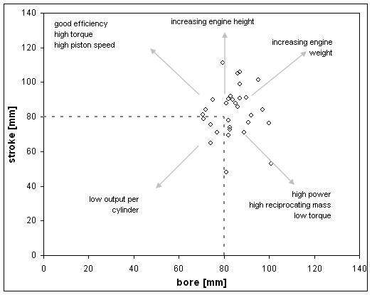
this image of bore and stroke has a number of data points added from fullsize engines

piston-002.jpg


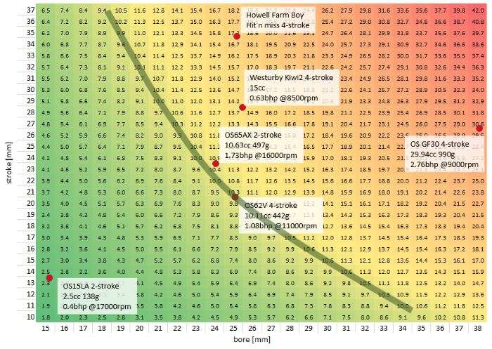
I then created a plot with data from some model engines, the green line is a 10cc line. The data in the cells is engine capacity.

engine-bore-and-stroke.jpg
 
Methinks that adding something like the very large, but also very efficient wartsila sulzer engine might complicate the graph and the plotting.
Remembering something like a 0.96 m bore and a 2.5 m stroke.

It's quite interesting to just build a large sheet of engine data and plot it in different ways. Adding very large engine data would then allow you to see parameters like mass versus capacity. I will have to dig out the data sheet I have and see what I can add.
 
The proper way to determine the correct size Walbro carb for an application is to use this formula:

D = K x Square Root(C x n)
where:
D=venturi diameter, in millimeters
K= constant between 0.65 and 0.90 (determines the smaller and the biggest diameter to be tested at the specific engine)
C=cylinder displacement, in cubic centimeters
n=RPM at peak power/1.000 (be realistic, dreaming only will make you try carbs far bigger than the correct, with results below your needs)

Lohring Miller
 
Applying the Walbro formula to a dozen model engines of which I know the dimensions ALWAYS result in a Calculated Air Speed at 6000 RPM of 158 m/s using K=0.65 and 74 m/s using K=0.9.
This is not a coincidence, the Walbro formula is based on obtaining a specific Venturi air speed. The equation is an inside out inversion to spit out the desired dimension based on what is known (RPM and Displacement).

The actual air speed is more than double because of the typical 0.125" 0.156" diameter spray bar effect on a typical 0.25" diameter Venturi.

Walbro product are tailored to the small engines like trimmers and chain saws. Walbro carburetor do not have the same type of metering as the typical model engine (Spraybar) so is questionable how far the formula can be applied to engines much smaller or much larger that a chainsaw engine
 
Subtracting spray bar area from venturi area is not difficult. 120m/s or more works well for me in model aircraft engines, though some as supplied can approach 80. I've looked at these figures for many engines. Empirical data like this is fairly easy to find. The formula works for all cases. As always, there is a range of what works depending on how much fuel suction you need and how much power loss you can tolerate. Carbs with boost venturi are at the lower end of velocity. Low performance engines seemingly at the high end due to poor volumetric efficiency. Volumetric efficiency of homebuilt model engines with small valves, lift, and duration can be low, so don't kid yourself.
 
Keep in mind that this estimated carb size would allow an engine to make full torque at that RPM. Just because you use a low RPM to estimate carb size doesn't mean it will restrict the engine to that RPM the load is low or nonexistent. Maybe this doesn't need to be pointed out, or maybe it does.
 
sonic air intake speeds ? totally impossible , car petrol engine , nothing like it , 10-15 cc model engine struggles to idle from (more than anything)from poor atomisation , you can scale the motor down but not the air , or more to the point the droplets of fuel in the air fed into your tiny motor , none of these models seem to heat the intake manifold , this is common on car engines for the same atomisation/vaporisation reason , will run smoother/slower at idle. above idle as air volume increases as crank speed increases this becomes gradually less vital , in fact a cooler/denser air fuel mix will improve out put , but would be hard to duplicate on such a small scale , have your exhaust exit/pipe touch or ecapsulate your intake tract/manifold somehow and then you should be able to achieve a slower crank speed/idle
 
At model size short distances and small air and fuel flow volumes often mean boiling fuel in the carb is a bigger problem than atomization. Carbs are often oversize which is what we are trying to help with here.
 
Gordon, you asked the right question here... but there are so many options for variation I think you may need to consider a new question.... what fuel permits really slow running?
Thinking of the physics: what you are trying to do is have a very small bang, at the hit, with a miss period of whatever results, with the flywheel inertia storing the energy from the hit, and bearing friction taking out energy as well as pumping losses.... so:
I reckon that gas will be a better fuel, as carburation may be easier than with liquid fuel atomisation...
I guess a small bore with long stroke will help slow running. A massive flywheel will reduce top speed after the firing stroke, (e = Mr w sq.).
Minimal friction in bearings and from piston rings is a must...mate ptfe?
Retarded ignition will be necessary for slow running. Near TDC.... maybe as little as 5 degrees advance?
Cheat. Use a 1/2" or 3/4" bore (and cross-head?) so it looks like a 1" bore... but isn't!
Cheers, K2.
 
I am at kind of a problem with this engine and there seems to be as many backwards steps as forward steps. I initially made a pinned and Loctite crankshaft. I ended up shearing off the pin so I used a larger pin. Sheared off that also so I made a one piece crankshaft. I don't know what was wrong with that one but there must have been a hard spot in the journal and it kept galling the connecting rod and seizing. Not sure why but it happened several times. I am presently making a new one piece crankshaft. I also had good compression and suddenly the compression has dropped off. I will have to try some new rings. Fortunately I made a bunch of extras. This engine seems to be jinxed.

Incidentally the original Rumley engine had 12" bore and 15" stroke so my 1.25 bore x 1.5 stroke is about right at 1/8 scale. The original engine however was basically a diesel running on kerosene.
 
More importantly where are the build pics of this rumley?
 
No build pictures. I am not very good at remembering to take pictures. Also my shop looks like a mess so I am hesitant to show the world. I do have a couple of pictures from when it was running before I decided to try to "improve" it.
 

Attachments

  • Rumely-1.JPG
    Rumely-1.JPG
    167.6 KB · Views: 147
  • Rumely-2.JPG
    Rumely-2.JPG
    169.7 KB · Views: 139
  • Rumely-3.JPG
    Rumely-3.JPG
    171.5 KB · Views: 141
  • Rumely-4.JPG
    Rumely-4.JPG
    163.6 KB · Views: 145
You won't notice a difference in RPM changing out the crank of a different stroke nor a smoother runner because of such. These parameters lie elsewhere in balancing of the rotating assembly and mounting isolation, fuel induction pathway diameters and flywheel inertia. Since the flywheel is the largest object on the crankshaft, this would most likely generate the desired slowdown plus not interfere with your engine design. And easiest to manipulate by machining length and diameter, having to be heavier and/or of greater diameter for a slowdown. Fuel/Air restriction another possibility, almost seems like the short answer in cutting back RPM. Many models find a natural run place to be no mater what you do at the intake though.
 
Last edited:
Hi Gordon,
On a different part of your model... What is inside the "Chimney"? Is is a baffled silencer, or just a large empty space for expansion of the exhaust gases to reduce the pressure wave at the top?
I haven't previously thought of making a hit n miss traction engine, but of course it was a logical evolution from Steam to IC. I must try and find some plans... (Though I have more than a lifetime full of plans already to fill retirement!).
Hope you can try a "Solid" flywheel, smaller carburettor or something to see what can be done to slow your engine....?
K2
 
Looking at lots of torque curves it would seem that long stroke would tend to give a flatter torque curve and a bigger bore gives perhaps greater power but a stronger 'hump' for a torque curve.

Its fascinating to compare North American developed gasoline engines and European/Japanese ones. The two tend to be quite different - - - at least imo.

IIRC a higher compression ratio tends toward cleaner burning but also produces higher levels of NOs and with the cleaner burning higher levels of CO2 and CO - - - which today are real real bad. So today we are told to want engines that waste more fuel so that we create less CO2 or CO. It would seem that someone's forgotten that if you use a LOT less fuel less byproducts are created - - - - but - - hey - - - - who said that the public hysteria re: global warming and all of the miasma surrounding it was logical.
Your information is about 30 years out of date. Modern automotive petrol engines tend towards the highest compression ratio they can get away with (detonation limited). Usually somewhere between 9:1 and 12:1, turbo engines of course will be at the bottom of that range whereas naturally aspirated will be up the top. The catalytic converter (and very precise control of fuel:air ratio by the computer) cleans up the nasty emissions.

Back in the early days of emissions control in the US there was a trend towards lower compression ratios, but that was mostly because of the removal of tetraethyl lead from the fuel (it's nasty in and of itself, plus it clogs up catalytic converters). Modern fuel is much better and engineers have got a lot better at combustion chamber design.
 
Hi Kasey, didn't know that.... When was that applied?
K2
Dear K2,
LONG BEFORE WW1(1910) ALSO IN EUROPE then, TO THE BEST OF MY KNOWLEDGE. Cheaper cars had smaller engines too for economy. Only luxury cars had bigger bores. The split single engine I'm building is almost square at 48mm x 50 with shorter con rods compared to conventional for that type. eg Puch 250 sgs engine. These engine are noted for their torque because of the extra leverage they get at ignition compared to normal engines. Mine should also have more but maybe more wear on the main piston.
Hi Kasey, didn't know that.... When was that applied?
K2
 
Back
Top