Nice job on the pdf Steve

You are using an out of date browser. It may not display this or other websites correctly.
You should upgrade or use an alternative browser.
You should upgrade or use an alternative browser.
Bob Shores Pacifier Tribute
- Thread starter stevehuckss396
- Start date


Help Support Home Model Engine Machinist Forum:
This site may earn a commission from merchant affiliate
links, including eBay, Amazon, and others.
Nice job on the pdf Steve
Thanks. Hopefully it will help somebody someday.
Shipdisturber
Well-Known Member
- Joined
- Dec 7, 2016
- Messages
- 131
- Reaction score
- 41
This post picks up where we left off.
Well I was curious to see if the castings were any good. I was seeing some pits in the surface of the pieces and that made me a little nervous. I setup the oil pan casting and made some surface cuts. They looked pretty good so I surfaced the top of the casting down to size. The pocket for the crankshaft clearance was completed and all the holes were drilled and tapped if needed. The holes to mount the pan to the block are counter bored so mounting hardware will be flush and hidden when displayed. The pan will need to be bolted to the block to proceed any further.


Just in case anybody was wondering, the pan was held in the vise with about a half inch of vise jaw showing on the right side. Center "Y" was found using an edge finder between the jaws. The casting was then re-positioned center of the vise. With the flashing filed off, center X was found by centering on the casting. Y needs to be kept tight but X is not too critical. Because the mounting flanges need to be .200 thick when finished, I setup the oil pan onto a pair of 1/2 inch lathe tool blanks between the bottom of the flanges and the vise jaws. Then just touched off the blank to set the Z axis at -.200. If further information is needed email me and i can send over some 8X10 color glossy pictures with circles and arrows and a paragraph on the back of each one explaining what each one is too me used as evidence against me. I'd post them here but my photo bucket is 97% full and I have a ways to go in the thread.
The part about the 8x10 glossy pictures reminds me of the song by Arlo Guthry "Alice's Restaurant" back in the seventies is this by any chance intentional? Beautiful work I'm really enjoying the post.
The part about the 8x10 glossy pictures reminds me of the song by Arlo Guthry "Alice's Restaurant" back in the seventies is this by any chance intentional? Beautiful work I'm really enjoying the post.
Yes it was.
Very nice document PDF Getting Started Steve!
For sure it will help me a lot when touching this project. Will also save me a bunch of hours and avoiding making any mistake that could scrap the castings.
Thanks for that.
Edi
For sure it will help me a lot when touching this project. Will also save me a bunch of hours and avoiding making any mistake that could scrap the castings.
Thanks for that.
Edi
Progress!!
I made the cylinder liners. They are made with 3 steps in them. There is a .860, .850, and .845 inch step in the outer diameter. The block is also machined with steps so there are 2 press fits. Its a little tougher to make them like this but when installed the 1.500 inch long liners drop into the hole so there is only about .375 inches sticking out of the cylinder. They don't have far to go when pressing in but also they are almost perfectly aligned for the operation. The added work making the liners is worth the effort in that there is little chance for errors when doing the press fit.
The liners have also been honed and ready for pistons. They were done on a Sunnen honing machine owned by a club member. While there the mini bike engine was honed so it is ready when the time comes. Paint is engine paint from the local auto parts store.
Little bit of progress yesterday and today. Made the lifter bushings and got them pressed in. Lifters are made and installed.I also have made a start on the pistons.


Cogsy
Well-Known Member
Doing an excellent job as usual Steve. Can't wait to hear this one running. Really makes me want to get back into my Peewee build too.
Thanks Cogsy. I did get the pistons finished today. I also made the center bushing, bolted in the crankshaft and motored it in the lathe for about 10 minutes. I'm inching forward.
Also Got a new camera so pictures should look a little better.
Also Got a new camera so pictures should look a little better.
A little bit more to report. The pistons are finished. The wrist pins were completed and pressed onto the rods. The pins are pressed into the rods and float in the piston.

Shipdisturber
Well-Known Member
- Joined
- Dec 7, 2016
- Messages
- 131
- Reaction score
- 41
Great work on the rods, are the pins on the rod bottoms for splash lube?
Great work on the rods, are the pins on the rod bottoms for splash lube?
Yes they are. They are drilled up into the cap and through the bushing. Hoping the rod will splash and also force oil up to the crankshaft.
Hi Steve,
I would have thought you could have used Bob Shores own method of putting a clamp system on the wrist pin end of the con rod rather than it being a force fit.
Or wasn't there room to use that method?
I always thought it was a very good system for these little engines.
Bobs Posting.
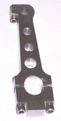
The clamp type rod offers so many advantages that I chose this design for the Pacifier V 4 engine that I am building. The small amount of time and labor to make this type of rod makes engine assembly and disassembly a more pleasant experience. The two photos below show the design.
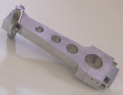
Five of these rods were made (1 as a spare), from 6061-T6 Aluminum to fit within .625" OD pistons. The cap bolts are 2-56 and the clamp bolt is 0-80. The .006" wide slot was sawn with a Jewelers circular saw blade given me by Jerry Keiffer. The threaded cross hole was counter drilled, by hand, with a No. 53 drill in a pin vise. A thin piece of brass shim stock was placed in the slot to prevent the clearance drill from going too deep.
Wider slots can be sawn with no ill effect. Very little torque is required on the 0-80 bolt to firmly clamp the wrist pin. Here are some of the advantages:
Actually, the time and labor to make a clamp type rod is offset by the time and labor to accommodate a typical tang eye type rod.
Bob Shores
Ruskin FLA
John
I would have thought you could have used Bob Shores own method of putting a clamp system on the wrist pin end of the con rod rather than it being a force fit.
Or wasn't there room to use that method?
I always thought it was a very good system for these little engines.
Bobs Posting.
The clamp type rod offers so many advantages that I chose this design for the Pacifier V 4 engine that I am building. The small amount of time and labor to make this type of rod makes engine assembly and disassembly a more pleasant experience. The two photos below show the design.
Five of these rods were made (1 as a spare), from 6061-T6 Aluminum to fit within .625" OD pistons. The cap bolts are 2-56 and the clamp bolt is 0-80. The .006" wide slot was sawn with a Jewelers circular saw blade given me by Jerry Keiffer. The threaded cross hole was counter drilled, by hand, with a No. 53 drill in a pin vise. A thin piece of brass shim stock was placed in the slot to prevent the clearance drill from going too deep.
Wider slots can be sawn with no ill effect. Very little torque is required on the 0-80 bolt to firmly clamp the wrist pin. Here are some of the advantages:
- The wrist pin can never touch the cylinder walls. This eliminates setscrews, pins, pads retaining rings, etc..
- The wrist pin should be a light push fir in the piston. This eliminates pressing the pin in the piston and the use of a drift pin and a hammer to remove the pin. The wrist pin can be removed and reinstalled many times with no damage to the piston or adjacent parts.
- The bearing surface in the piston is usually greater than the bearing surface in the rod bearing.
- If the piston gets overly hot, the wrist pin clearance becomes slightly greater.
- The wrist pin can be solid or tubular.
Actually, the time and labor to make a clamp type rod is offset by the time and labor to accommodate a typical tang eye type rod.
Bob Shores
Ruskin FLA
John
Last edited:
Little bit more. Had a few minutes this morning so I went out and made my fixture for heat treating the piston rings.
I am using the George Trimble method where the rings are turned and then cracked. They get loaded into this fixture
sprung open and heated to stress relieve them. When unloaded from this fixture they will retain the gap and need
to be sprung closed to insert into the bore.


I am using the George Trimble method where the rings are turned and then cracked. They get loaded into this fixture
sprung open and heated to stress relieve them. When unloaded from this fixture they will retain the gap and need
to be sprung closed to insert into the bore.
Hi Steve,
I would have thought you could have used Bob Shores own method of putting a clamp system on the wrist pin end of the con rod rather than it being a force fit.
John
Hello John. I know a couple people that built the rods in the picture. 2 of them have changed to the press fit because the screw has come loose. One scratched the cylinder wall when the wrist pin walked to the side. The other was fine until the screw fell right out and wedged and locked the motor. I guess I just don't trust the method. I would feel bad if I put it in the design and problems started popping up. Bob's Pacifier that eventually became the Peewee was never run under it's own power. All he got was some sputtering. I think if he would had a similar experience, the design would have gone by the wayside. If you stick with it I would advise some lok-tite on the screws and pray the heads don't strip if they ever need to come apart.
I wasn't criticizing you Steve, just asking a question as it seemed like Bob was so certain of the method, whereas you have provided details why it wasn't such a success after all.
Going by what you have said, I think that method will be consigned to the scrap bin.
John
Going by what you have said, I think that method will be consigned to the scrap bin.
John
I wasn't criticizing you Steve, just asking a question as it seemed like Bob was so certain of the method, whereas you have provided details why it wasn't such a success after all.
Going by what you have said, I think that method will be consigned to the scrap bin.
John
I didn't take it that way honest. I really wanted to go with the style you showed but I don't want to present a design that could become problematic for even one person. You spend months or years building these things and when you finally get them going you breath a sigh of relief that it's finally over. Whipped and sometimes beat up by the process you proudly fire it up for your pals and BANG!!. If your lucky you just put the screw in and away you go but if not, it's making a new rod or a cylinder liner. That would suck rocks.
Shipdisturber
Well-Known Member
- Joined
- Dec 7, 2016
- Messages
- 131
- Reaction score
- 41
Any diesel engine I've worked on or rebuilt (260 and counting) all pivot on the wrist pin and are secured in the piston itself. Lube is a factor there I believe it's easier to lube one centre bearing than two to the side. Then again big engines have more to consider than small engines.
OK! I have the rings turned, bored, and parted off about .001-.0015 wider than finished size. OD is between perfect and .0005 over size. You cant go under size. ID is +- .001. There are a lot of them but I needed extra in case of breakage. Also made a few sets for the mini bike engines.

Next the rings are cracked so they can be loaded onto the fixture. The Trimble method has a fixture with 2 blades that cleve the ring and create the gap. They look exactly like the jaws of a pair of diagonal cutters. So for years now I just use diagonal pliers. Just make sure the pliers are straight accross the ring before you squeeze. The ring just pops when it opens. The rings are then inserted onto the fixture with the gap spanning the dowel pin. The fixture is loaded into the oven.

The non-scaling powder requires the part be 500F degrees before applying so I power the oven on until it's 600 in the oven and turn it off and just let the fixture soak in the heat. Once the oven drops to 500 I remove the fixture and sprinkle the magic dust on it until it is heavily coated. The powder will melt when it contacts the metal and turn greasyish. Just jeep sprinkling until you don't see metal.
http://www.brownells.com/gunsmith-t...ccessories/non-scaling-compound-prod1122.aspx

Then back into the oven at 1100F for 4 hours. Now I'm not just pulling the numbers out of my rear. I sat and had a chat with one of the most respected metallurgists in the detroit area. We had discussion about the various methods and if your going to truly stress relieve a ring, this is the best way to go. So this is what I do. After the 4 hours expires I let the oven come down naturally to 500F degrees and remove the fixture and drop it into a pot of boiling water right away. The boil lasts about 10 minutes and it's ready to be taken apart.

The rings are removed from the fixture. The rings stay fully open so the treatment was successful.

The OD of the ring is cleaned up with a couple strokes of a scotch-bright pad. For the sides a tool is made. A small pocket is bored in the end of a scrap piece of rod to a depth .005 less than the final thickness of the ring and about .010 bigger than the final diameter. This will give an easy way of holding the ring while the sides are brought to final thickness and polished. I have had good luck doing circular or figure eight patterns when polishing. Keeps you from leaning on one side too much and turning the ring into a wedge.


So now I guess you all know what i'll be doing tomorrow.
Next the rings are cracked so they can be loaded onto the fixture. The Trimble method has a fixture with 2 blades that cleve the ring and create the gap. They look exactly like the jaws of a pair of diagonal cutters. So for years now I just use diagonal pliers. Just make sure the pliers are straight accross the ring before you squeeze. The ring just pops when it opens. The rings are then inserted onto the fixture with the gap spanning the dowel pin. The fixture is loaded into the oven.
The non-scaling powder requires the part be 500F degrees before applying so I power the oven on until it's 600 in the oven and turn it off and just let the fixture soak in the heat. Once the oven drops to 500 I remove the fixture and sprinkle the magic dust on it until it is heavily coated. The powder will melt when it contacts the metal and turn greasyish. Just jeep sprinkling until you don't see metal.
http://www.brownells.com/gunsmith-t...ccessories/non-scaling-compound-prod1122.aspx
Then back into the oven at 1100F for 4 hours. Now I'm not just pulling the numbers out of my rear. I sat and had a chat with one of the most respected metallurgists in the detroit area. We had discussion about the various methods and if your going to truly stress relieve a ring, this is the best way to go. So this is what I do. After the 4 hours expires I let the oven come down naturally to 500F degrees and remove the fixture and drop it into a pot of boiling water right away. The boil lasts about 10 minutes and it's ready to be taken apart.
The rings are removed from the fixture. The rings stay fully open so the treatment was successful.
The OD of the ring is cleaned up with a couple strokes of a scotch-bright pad. For the sides a tool is made. A small pocket is bored in the end of a scrap piece of rod to a depth .005 less than the final thickness of the ring and about .010 bigger than the final diameter. This will give an easy way of holding the ring while the sides are brought to final thickness and polished. I have had good luck doing circular or figure eight patterns when polishing. Keeps you from leaning on one side too much and turning the ring into a wedge.
So now I guess you all know what i'll be doing tomorrow.
After all the rings are polished and cleaned they are inserted into the cylinder so the end gap can be checked with the feeler guages

To open the gap i set them on a 1,2,3 block with the end overhanging a bit and gave them a few strokes with the file until the end gap was .003 - .005 inches

When all were done, the pistons were installed.


To open the gap i set them on a 1,2,3 block with the end overhanging a bit and gave them a few strokes with the file until the end gap was .003 - .005 inches
When all were done, the pistons were installed.
Similar threads
- Replies
- 283
- Views
- 59K
- Replies
- 151
- Views
- 28K