Going to give this project thread a little go. If no one takes anything from it, at least it will give me a nice run through of everything I did and the order/process I went through. My last project (Webster) was very much a first go, with a lot of learning and admittedly some impatience. This time I will be taking it much steadier, I also have a much broader set of tools and larger machine tools sat my disposal, and learned a lot since I started this hobby.
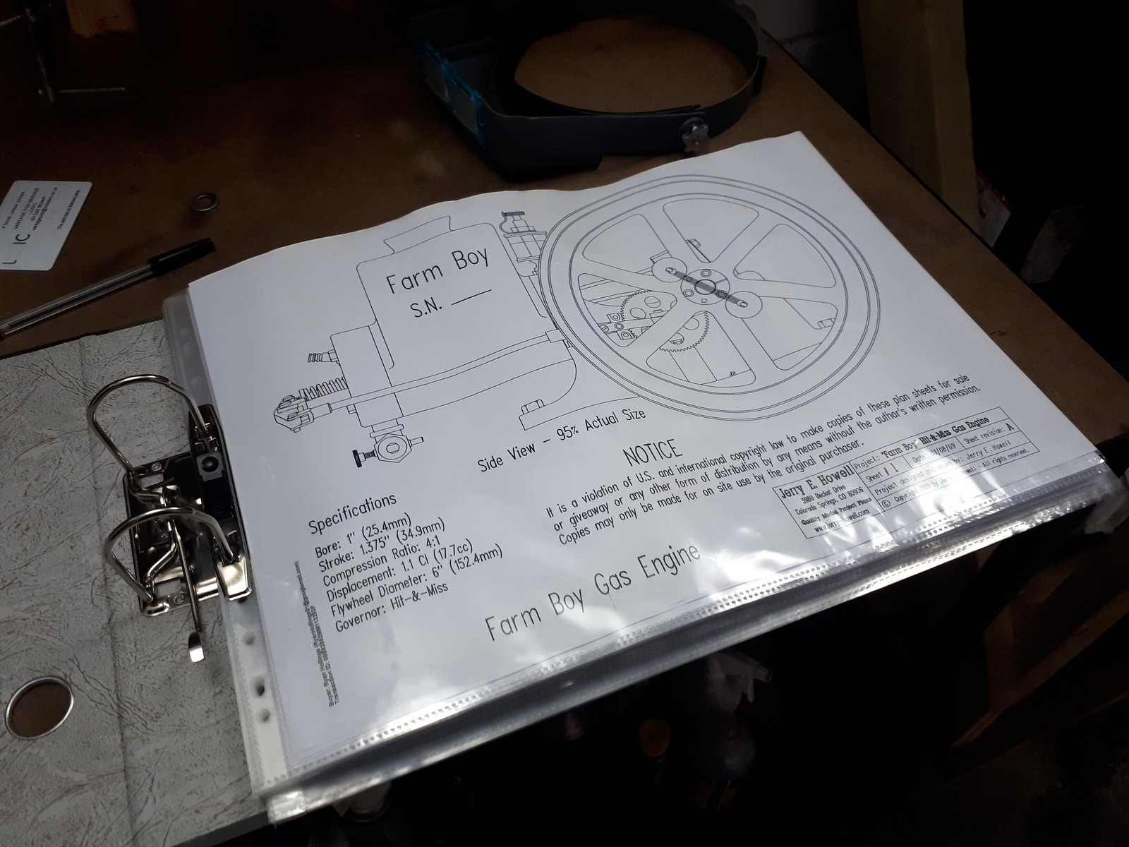
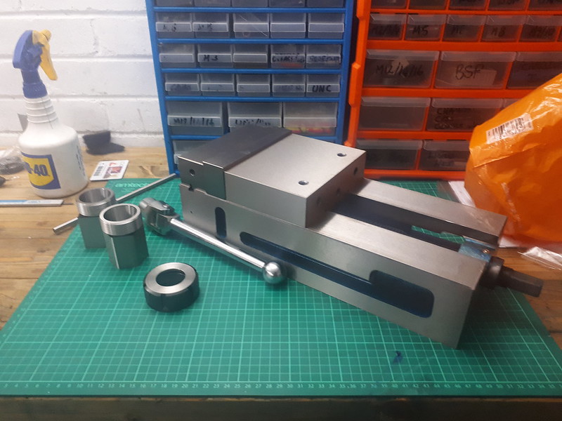
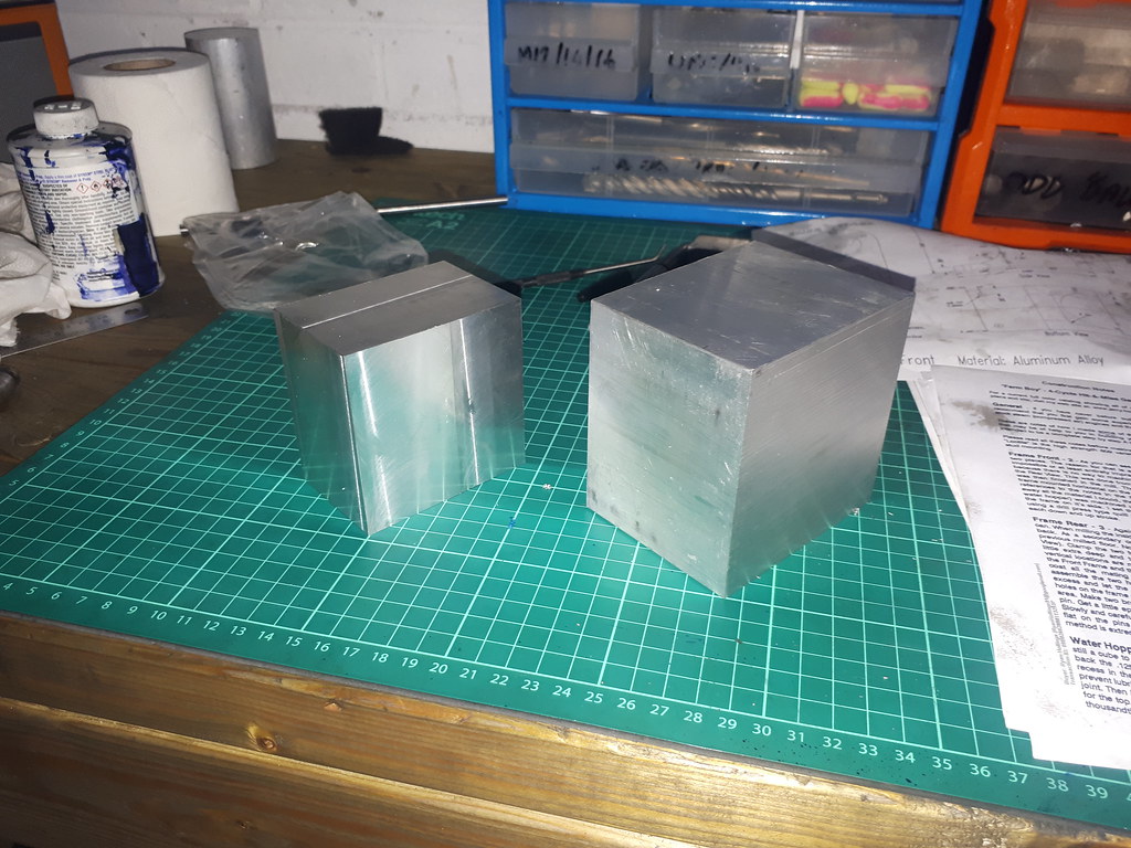
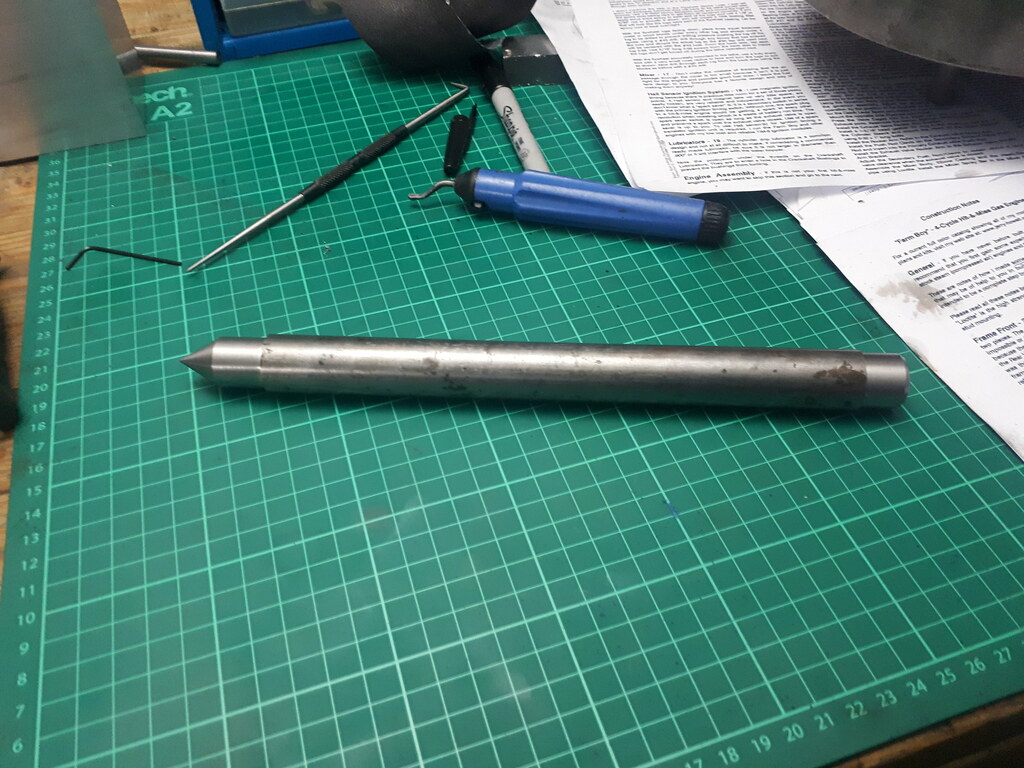
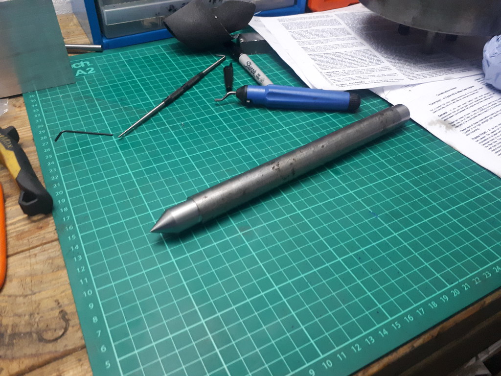
Some of the main stock materials laid out. Flywheels not yet purchased, some brass still to buy and crankshaft materials depending on which route I take to construct/machine it.

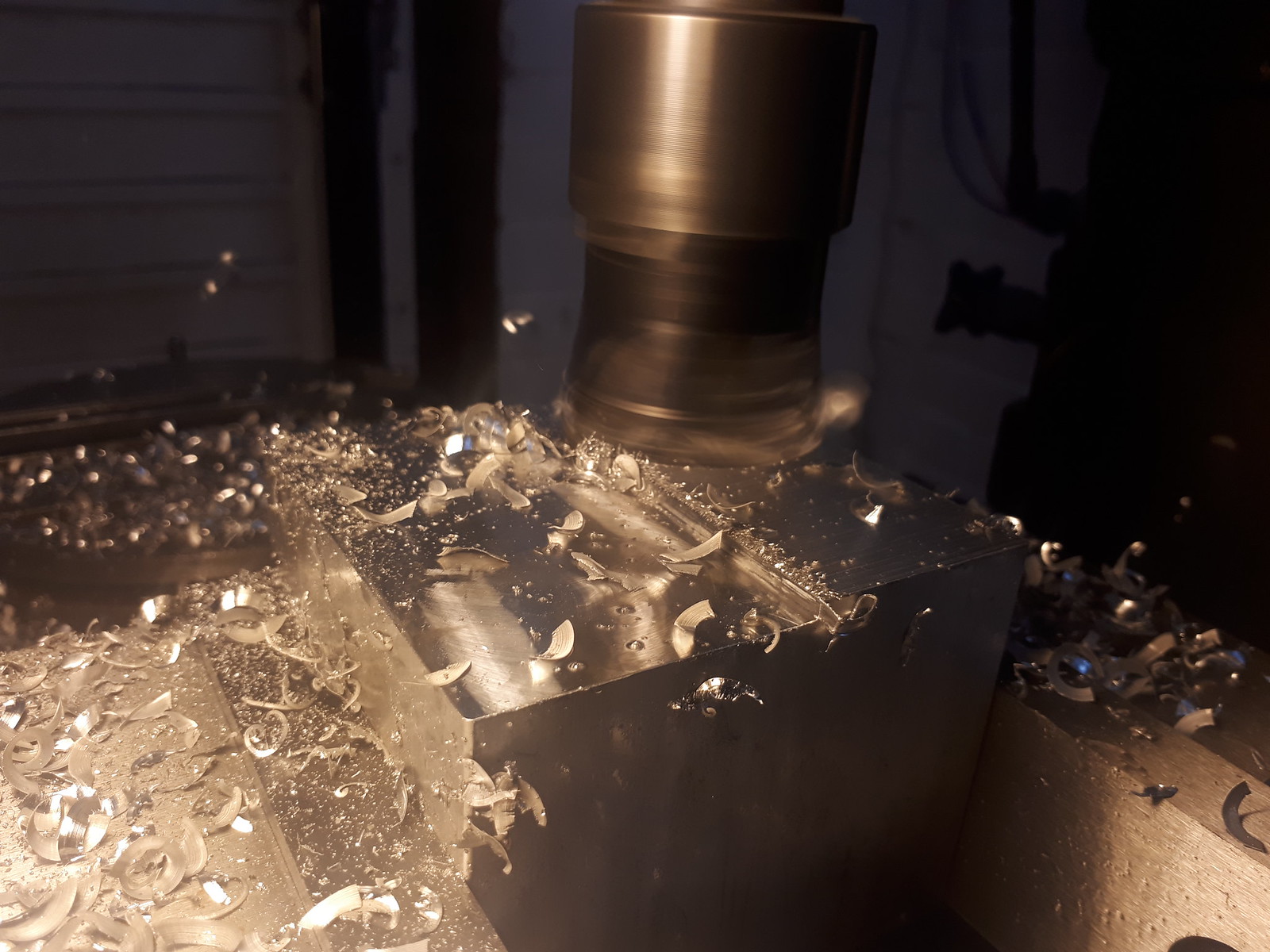
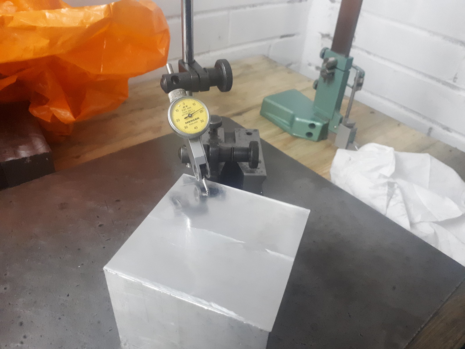
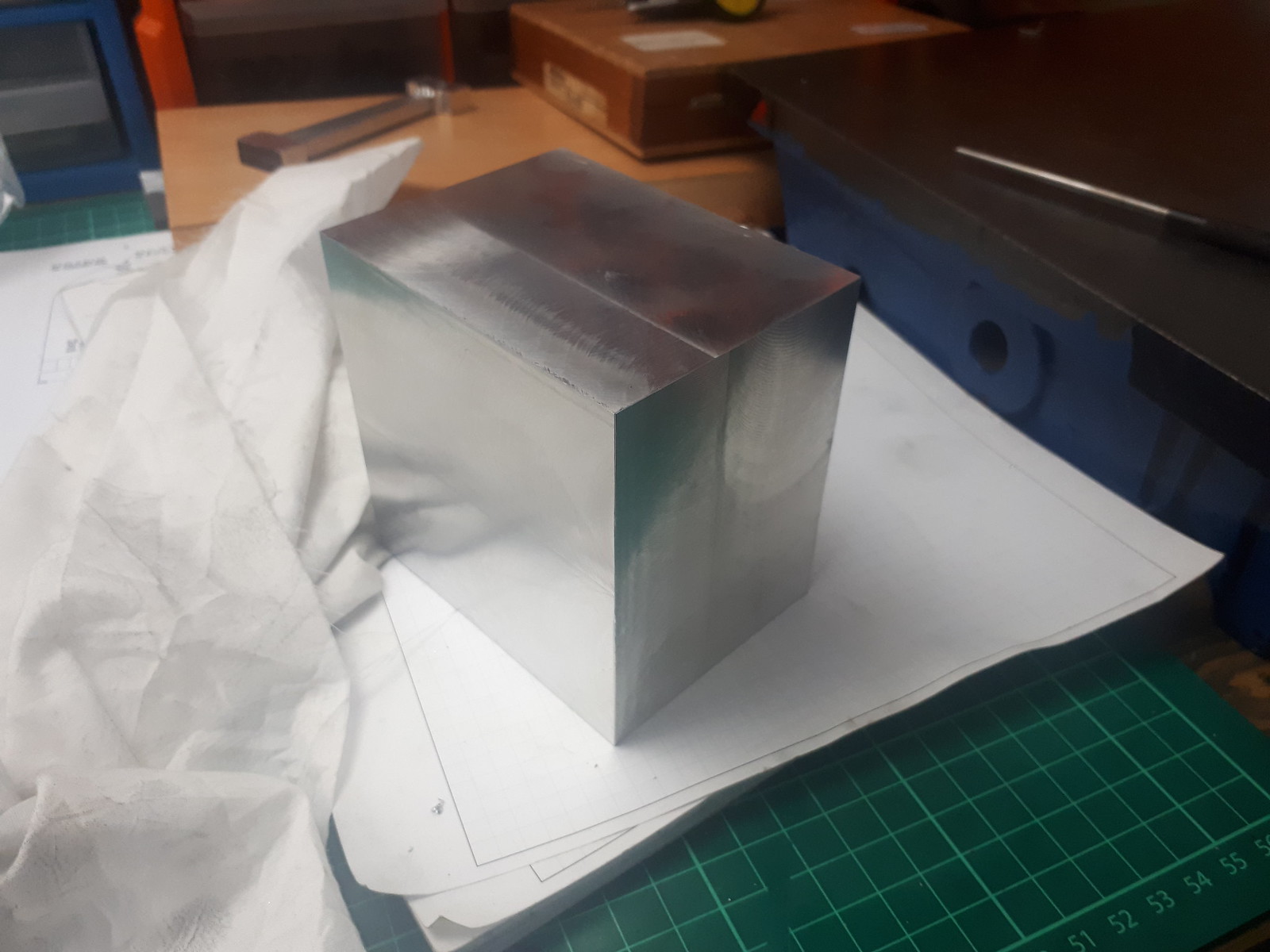
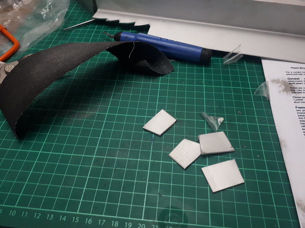
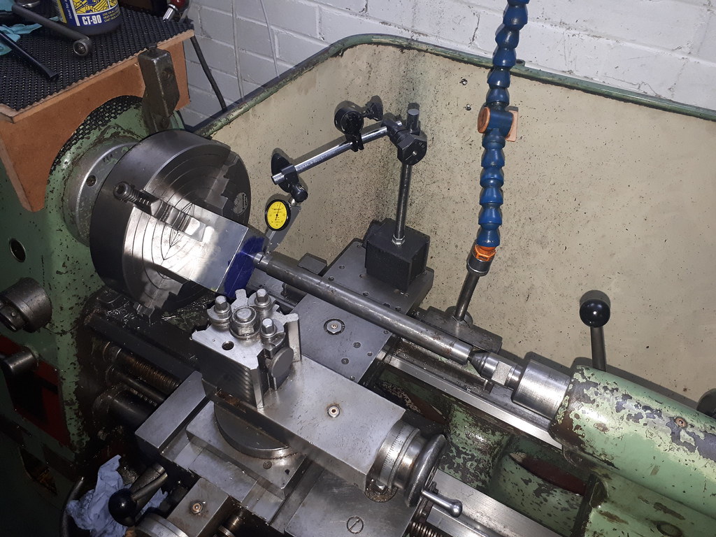
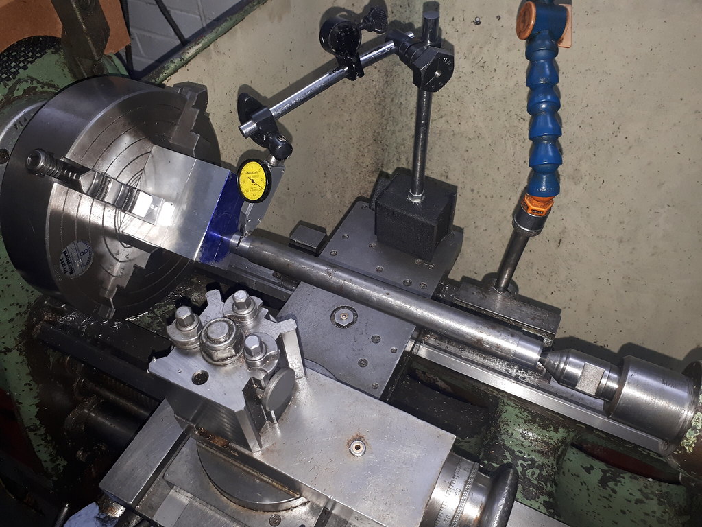
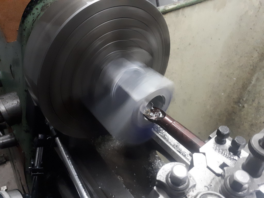
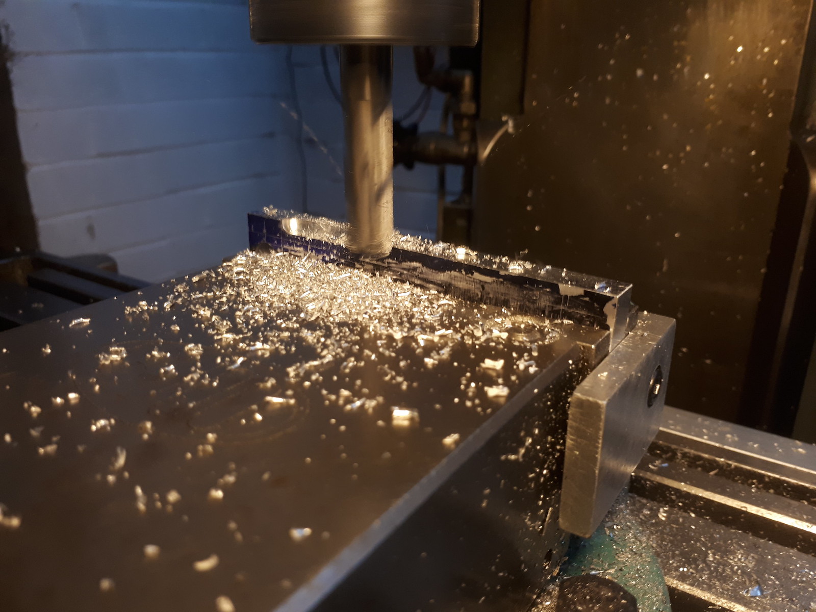
Whilst I wait for my 6" vice to arrive I decided to start work on the connecting rod. Laziness pushed me down the path of hogging away an pretty oversized piece of 2014A down to the correct size. Maybe I should make a power hacksaw first...
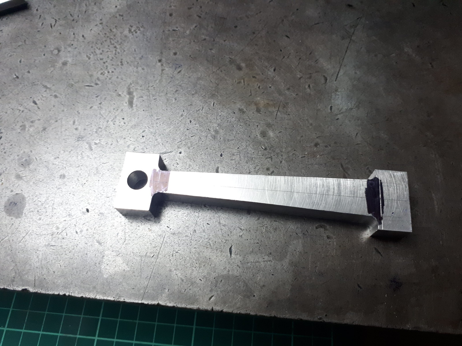
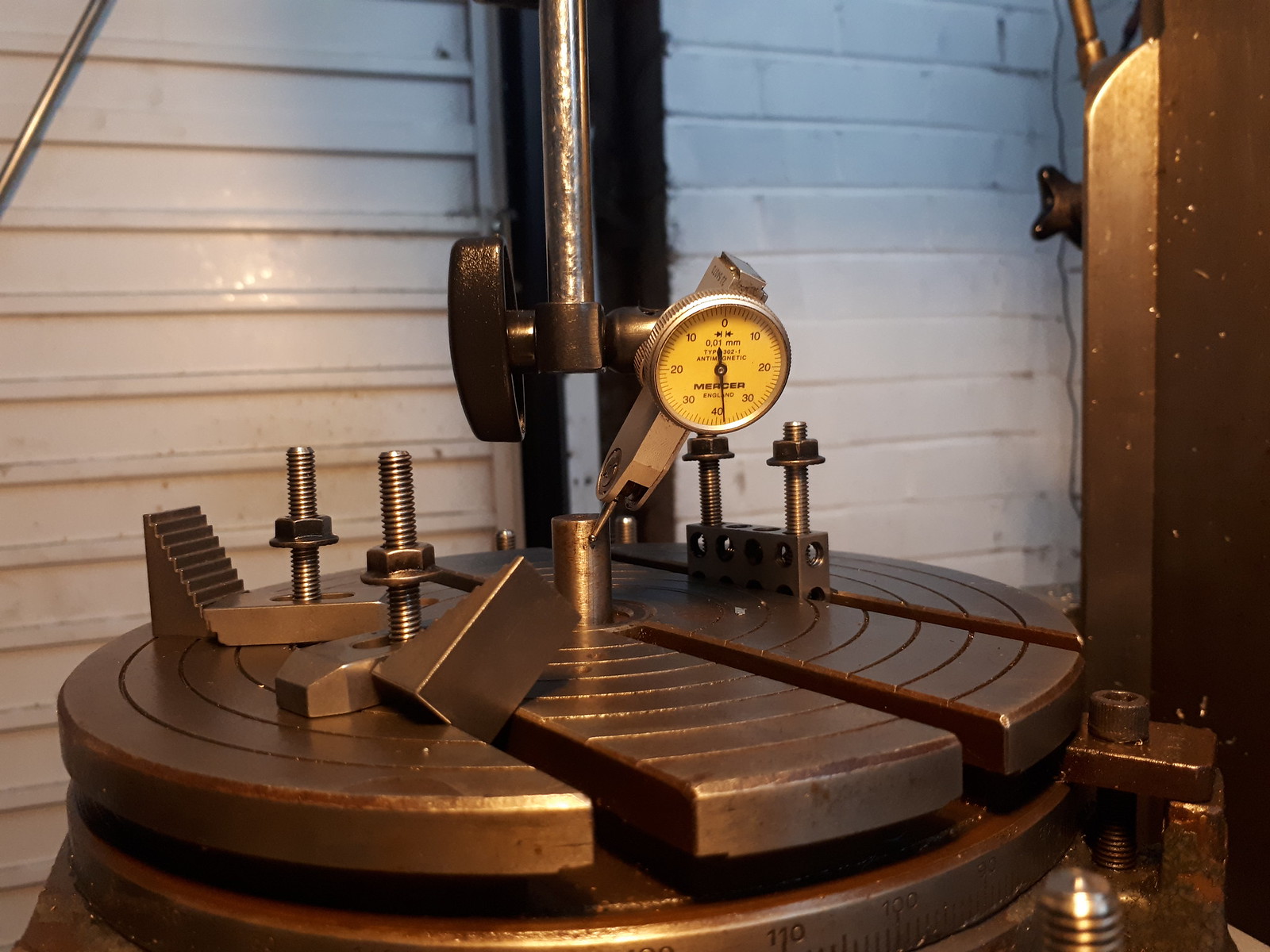
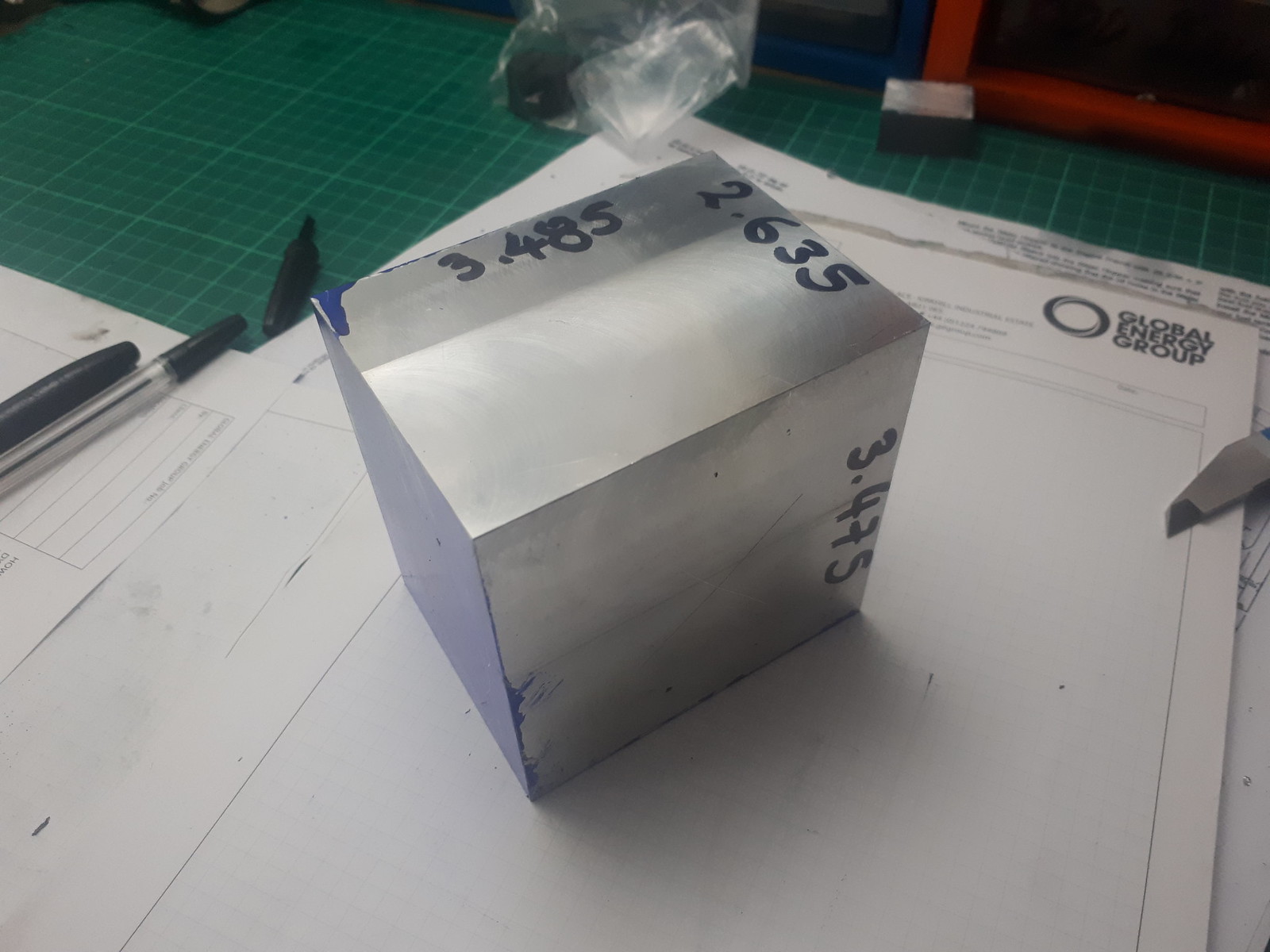
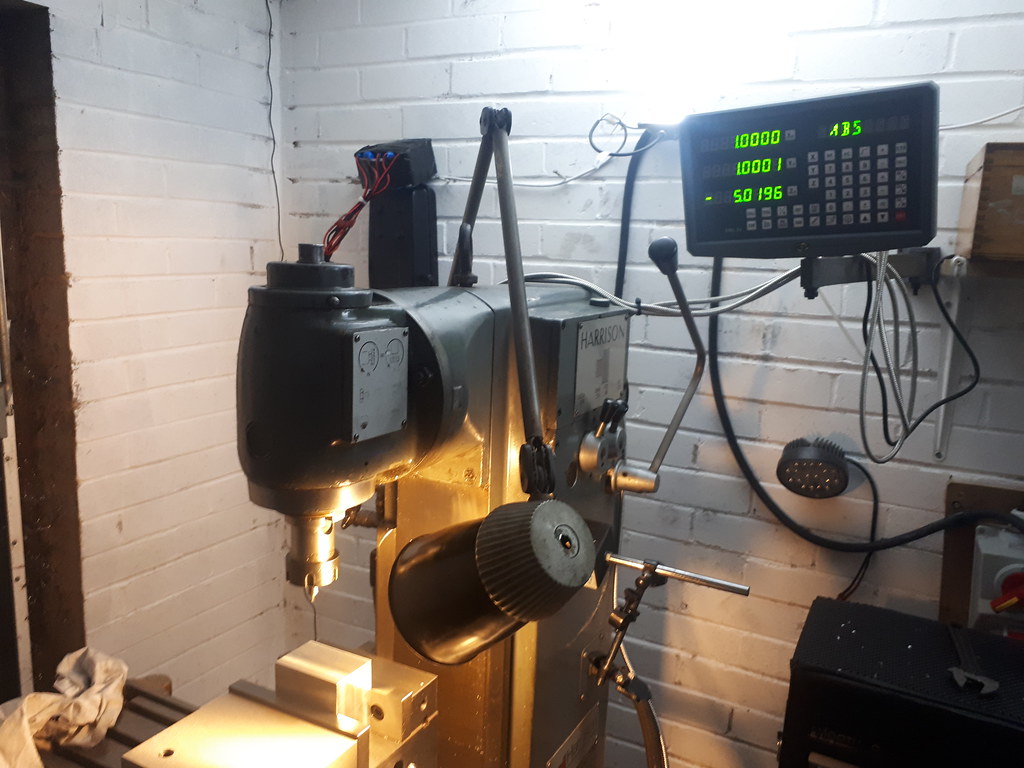
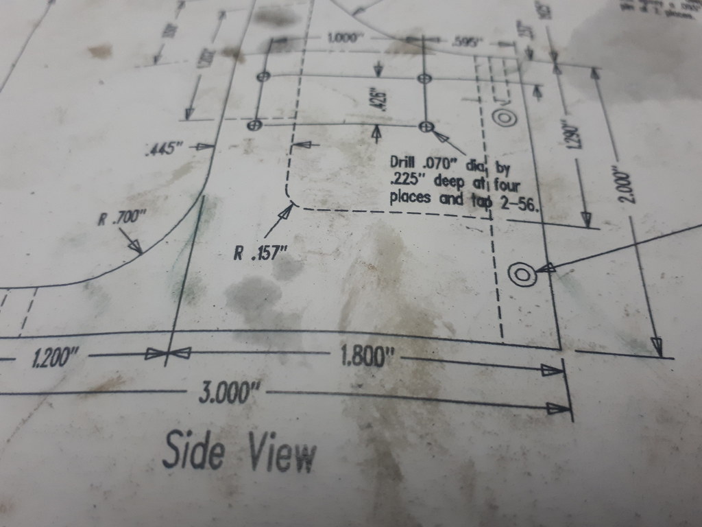
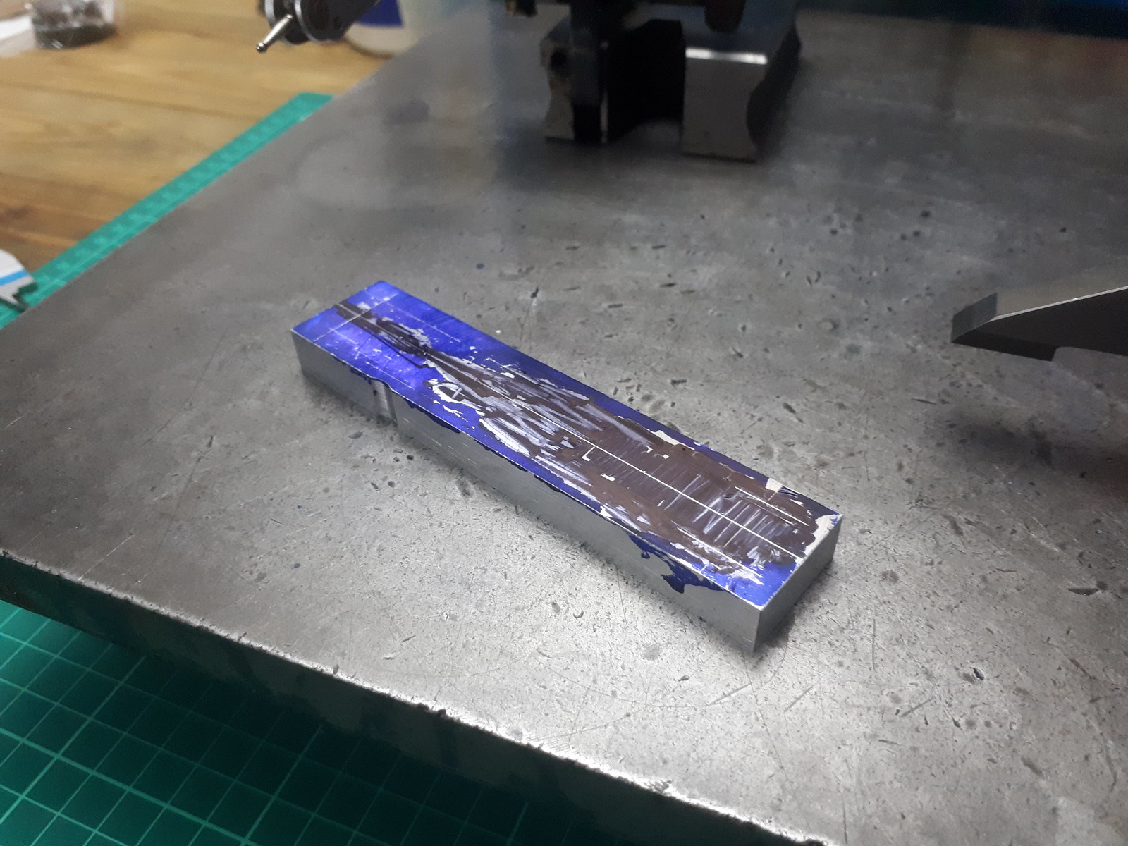
I will be making all critical cuts using the DRO but I still like the reassurance marking out gives. Some of the critical sizes marked, along with the lines to cut the angle between the little and big end. Difficult to see granted due to the Dykem not adhering too well to the machined surface (maybe some contaminants)
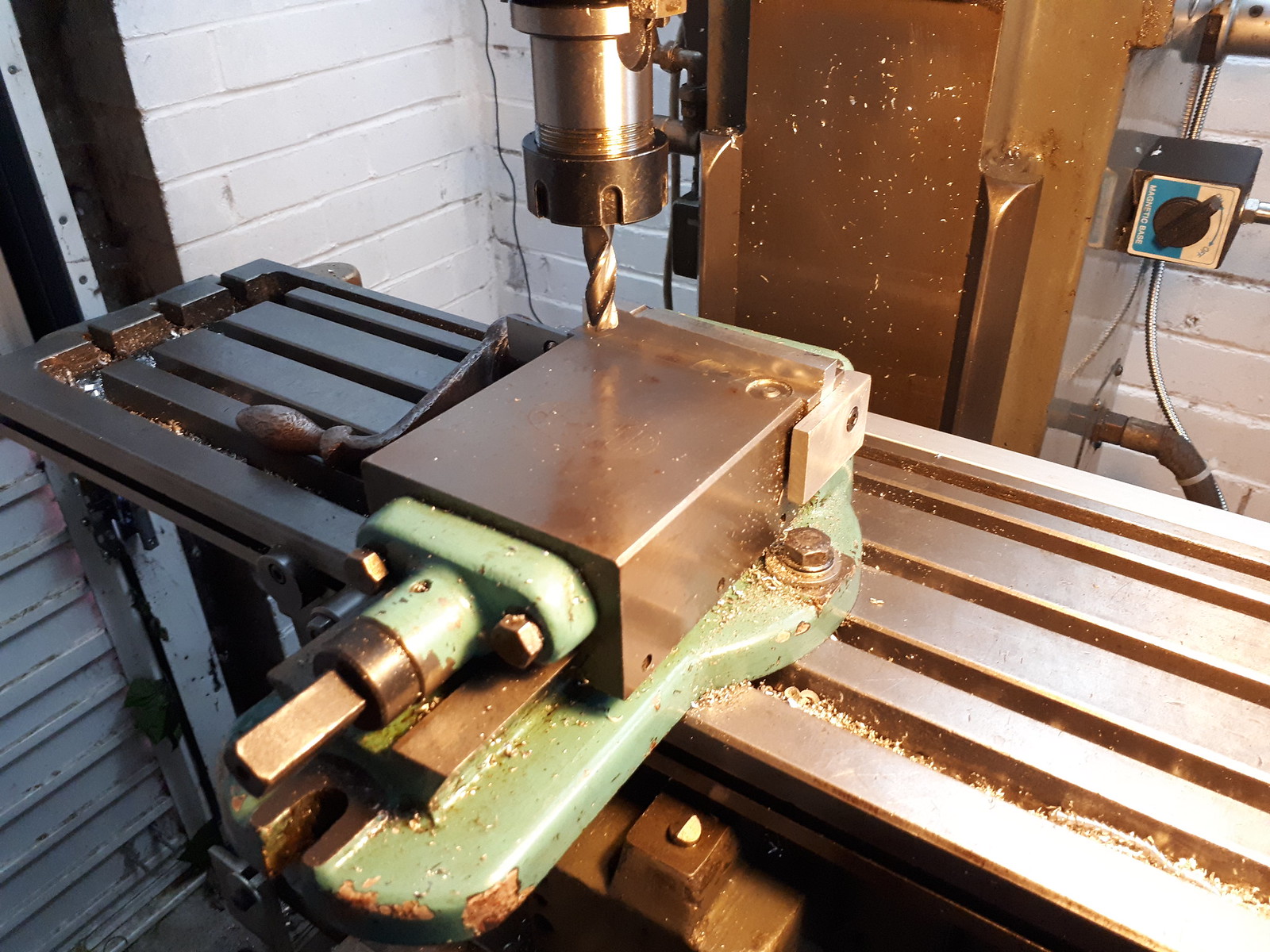
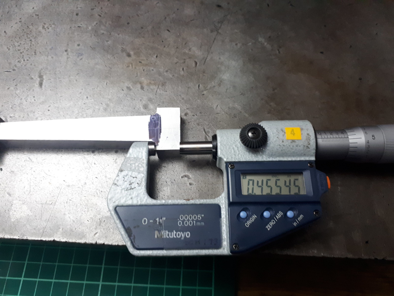
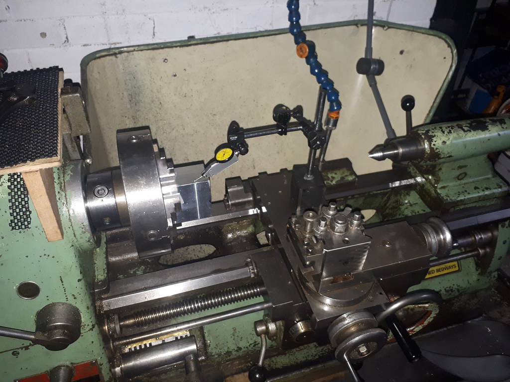
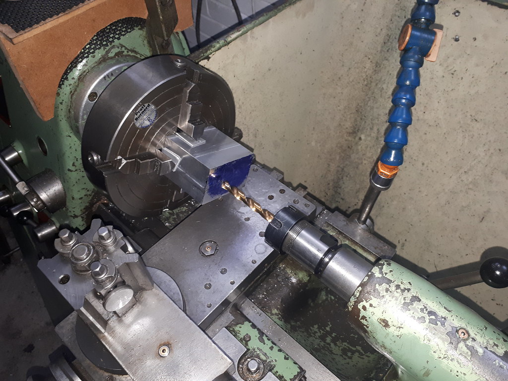
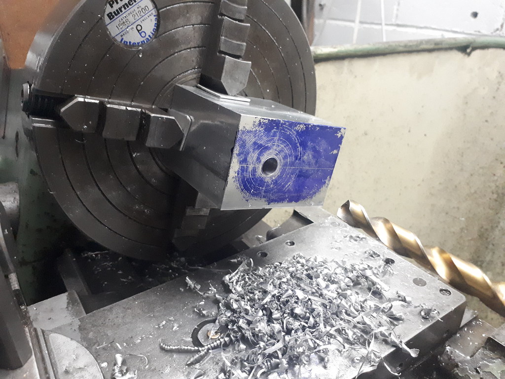
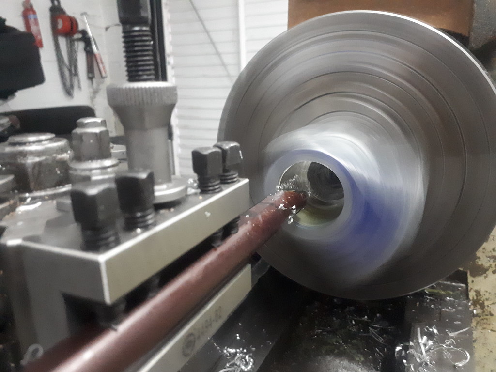
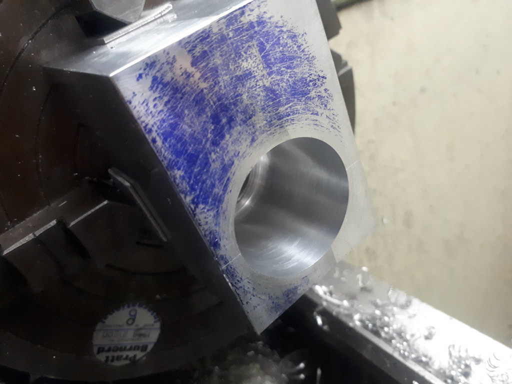
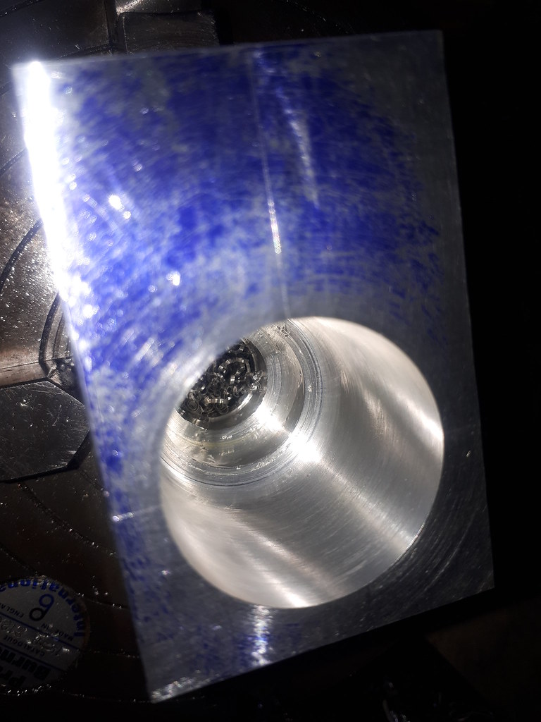
Never got any photos, but setup the piece in the vice, shaved a few thou off the big end flat and then wound up the 3.9" to the little end. Drilled, then reamed for 8mm.
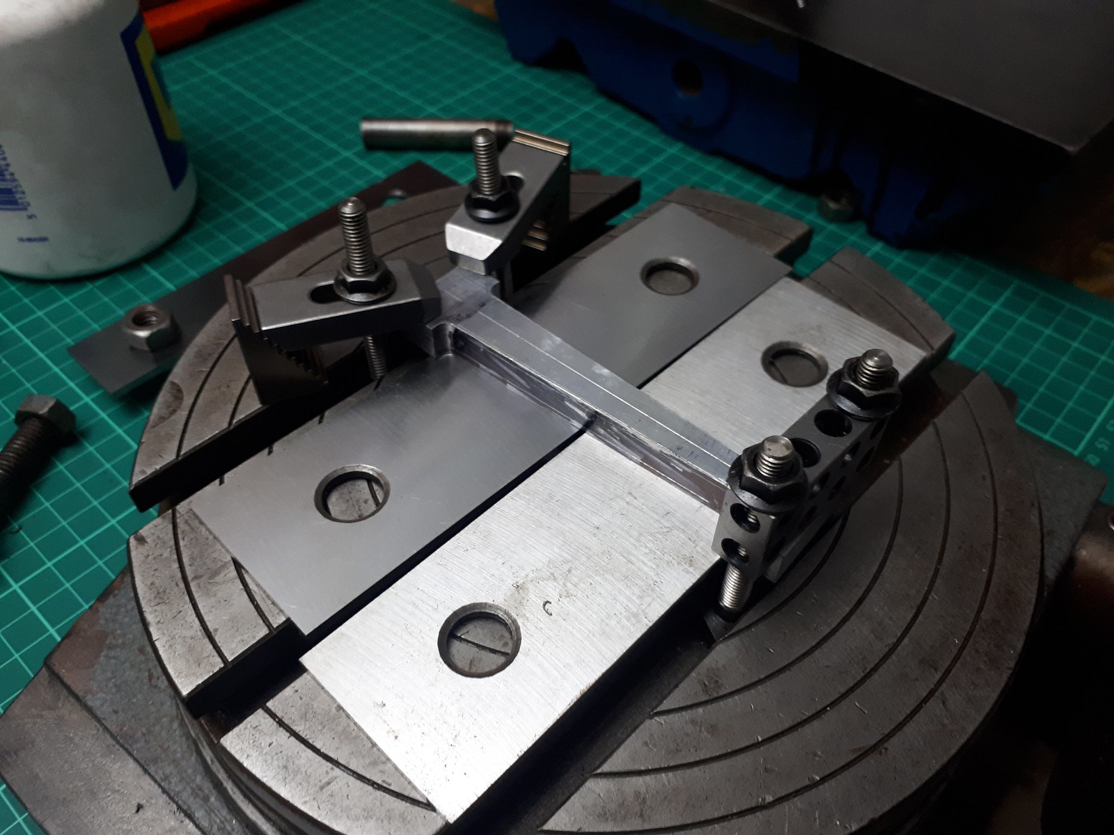
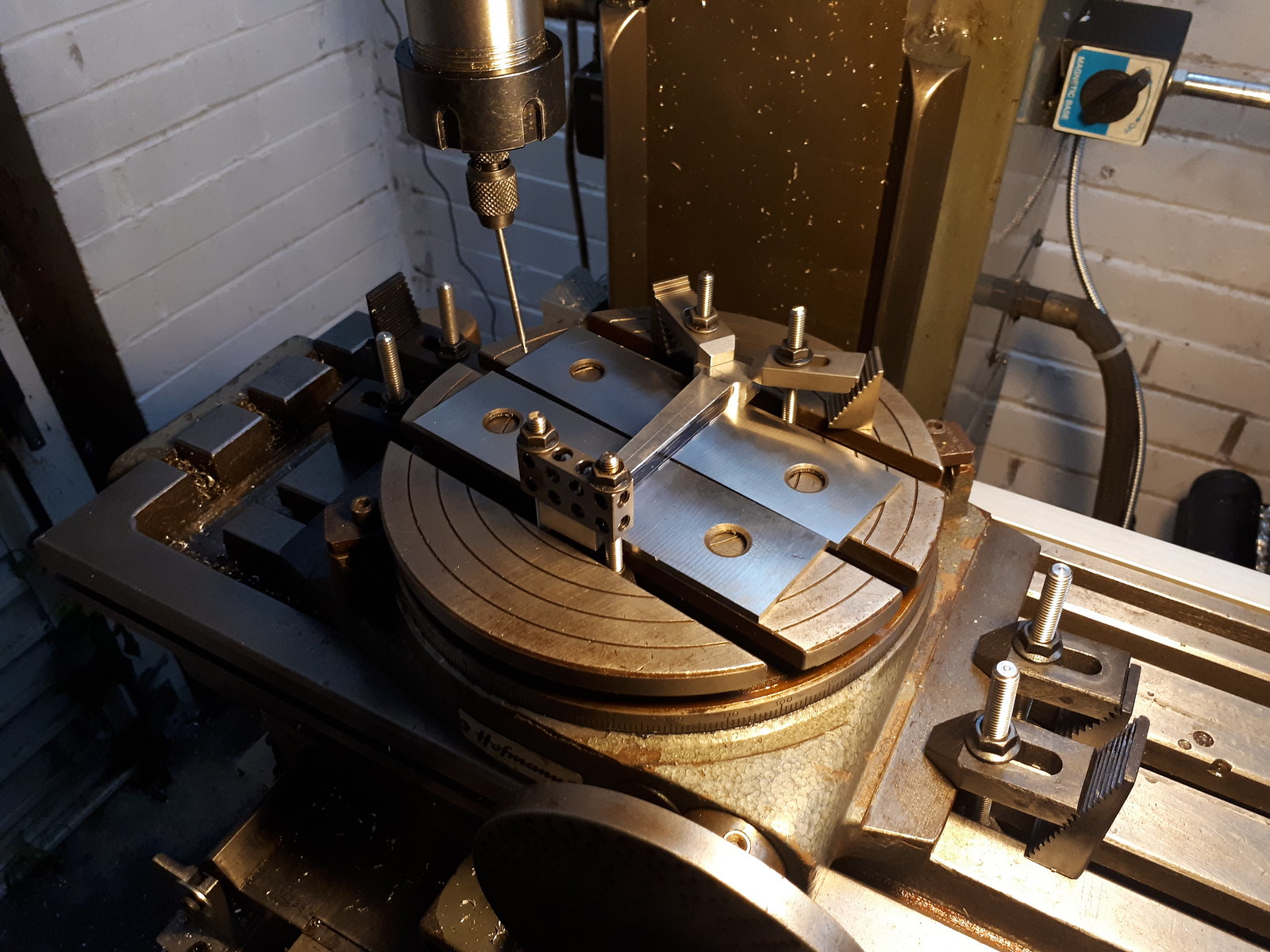
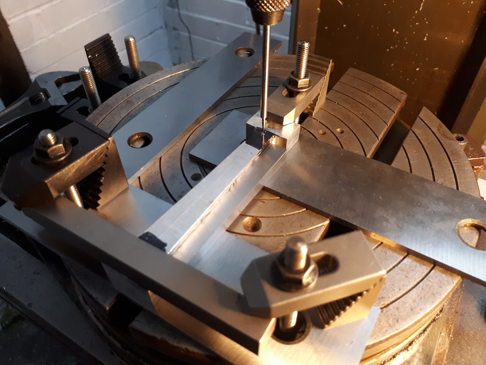
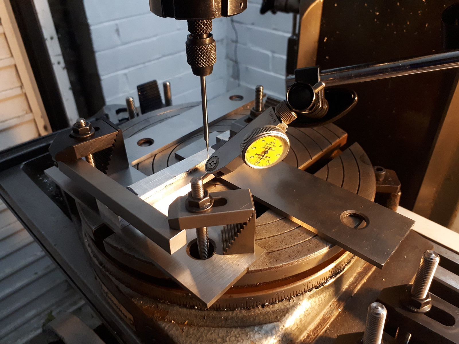
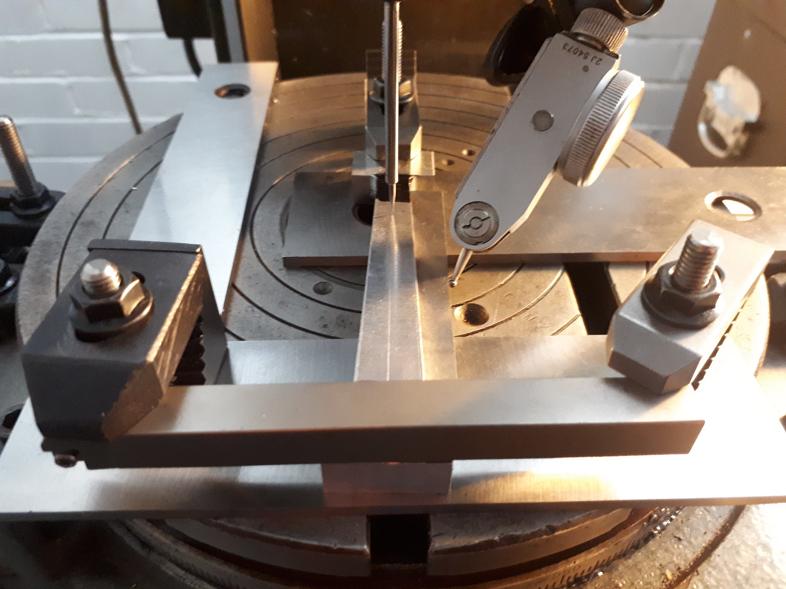
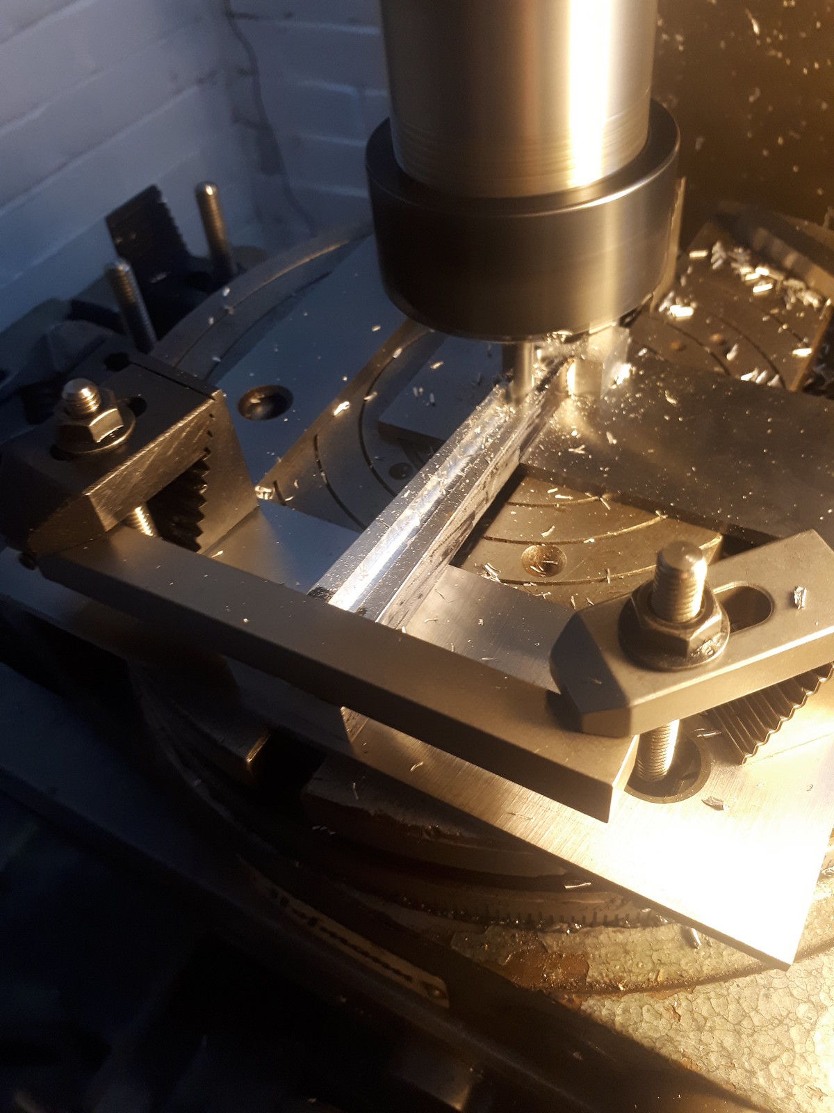
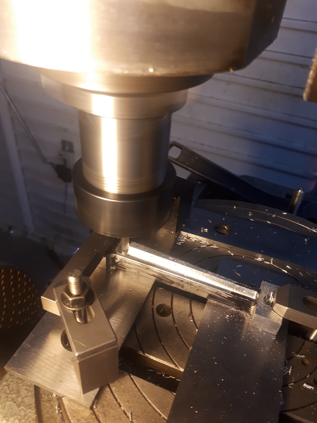
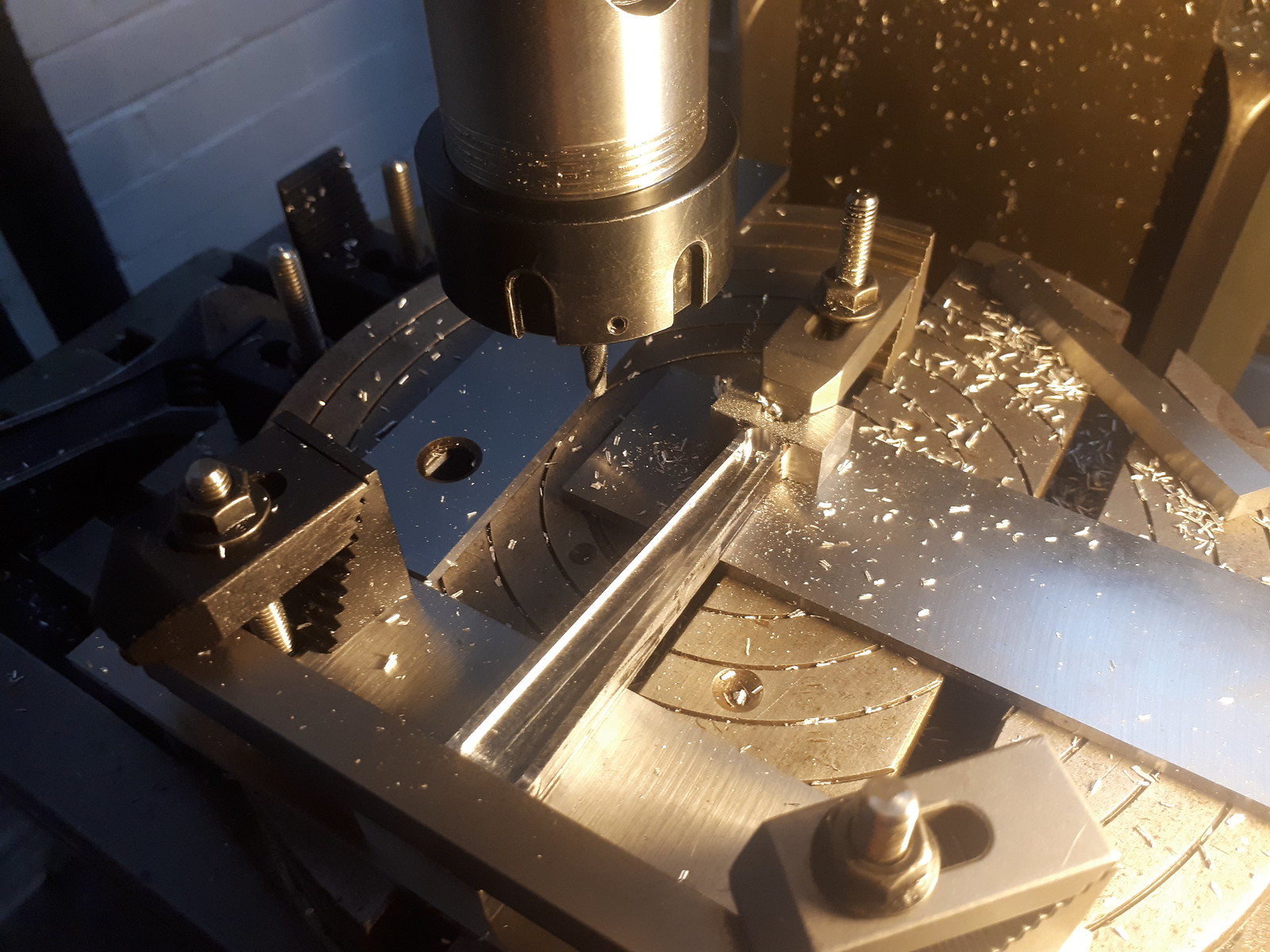
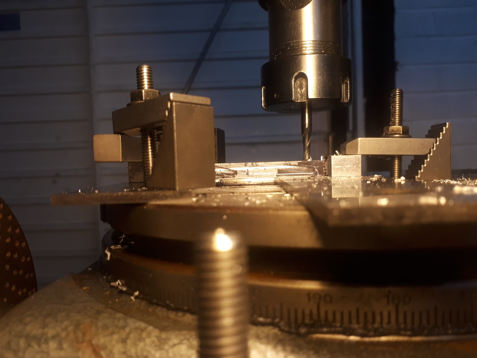
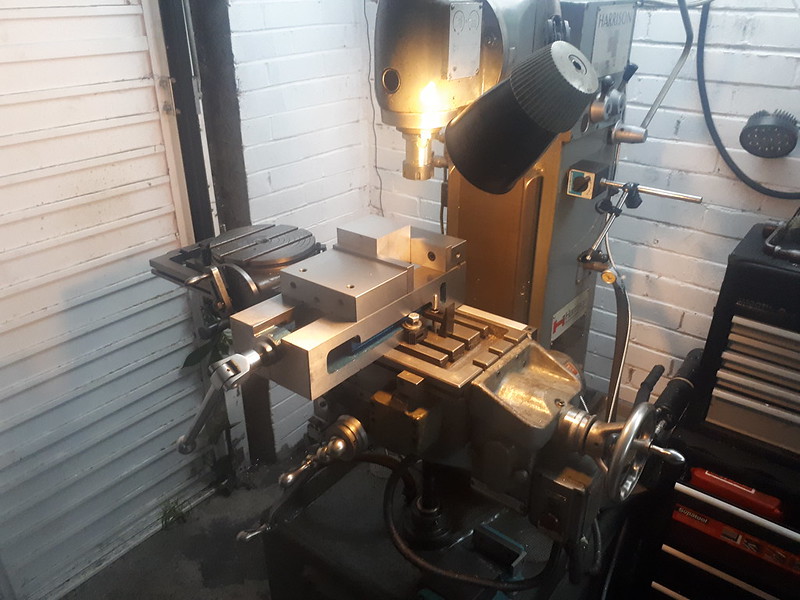
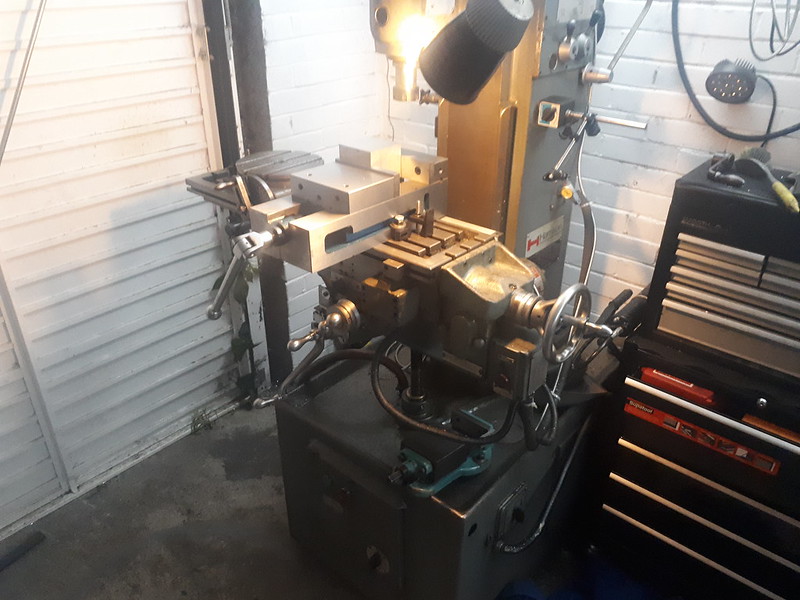
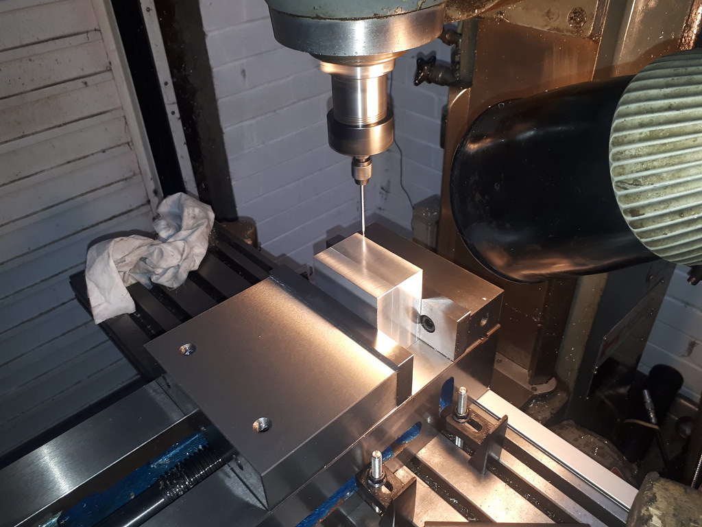
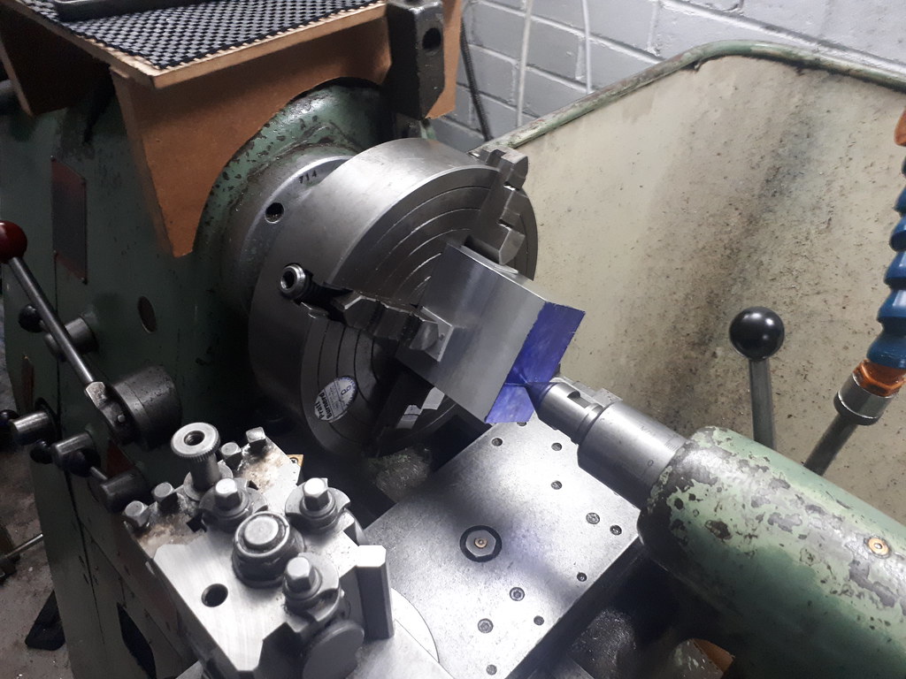
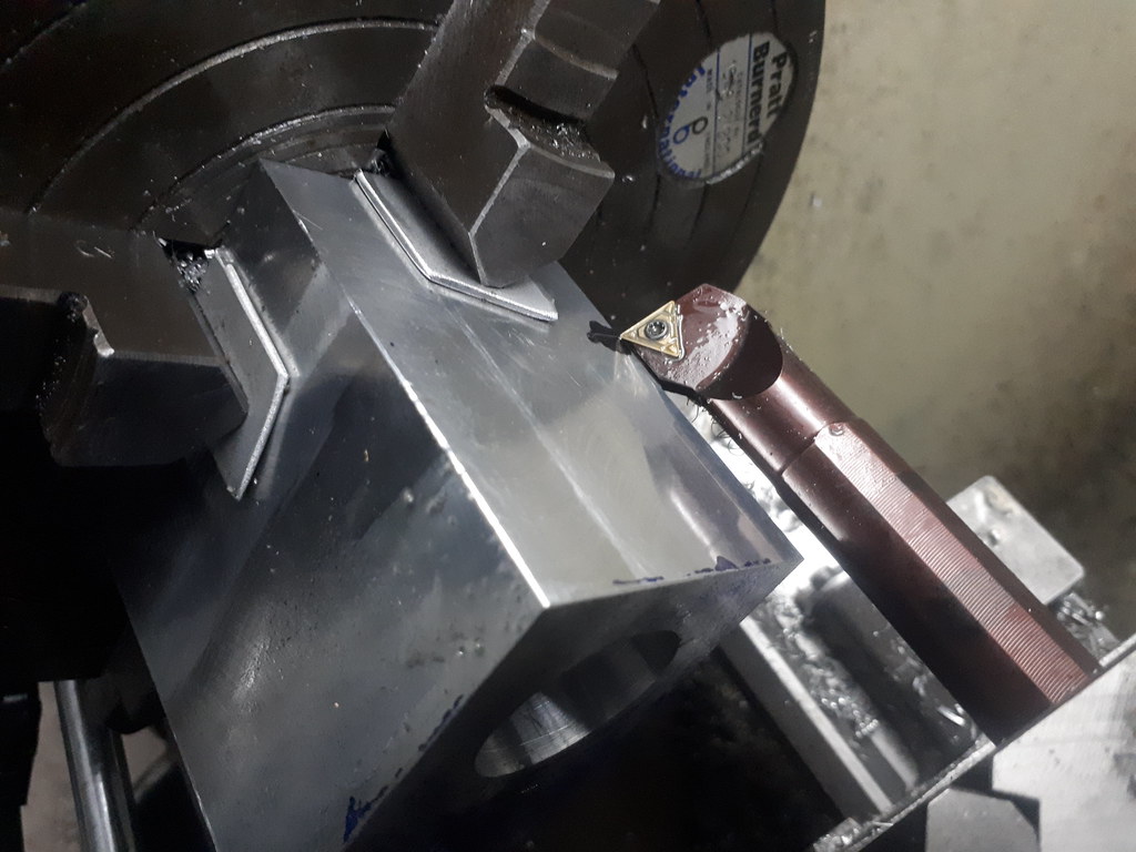
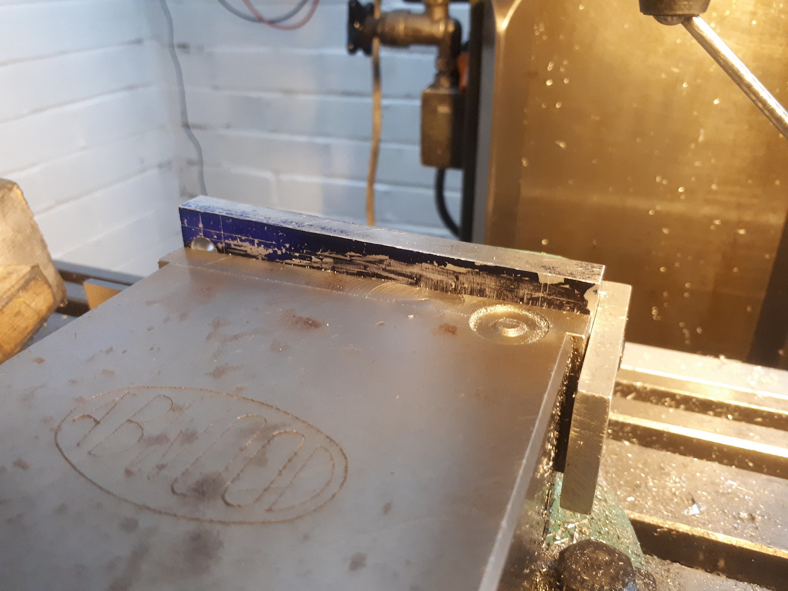
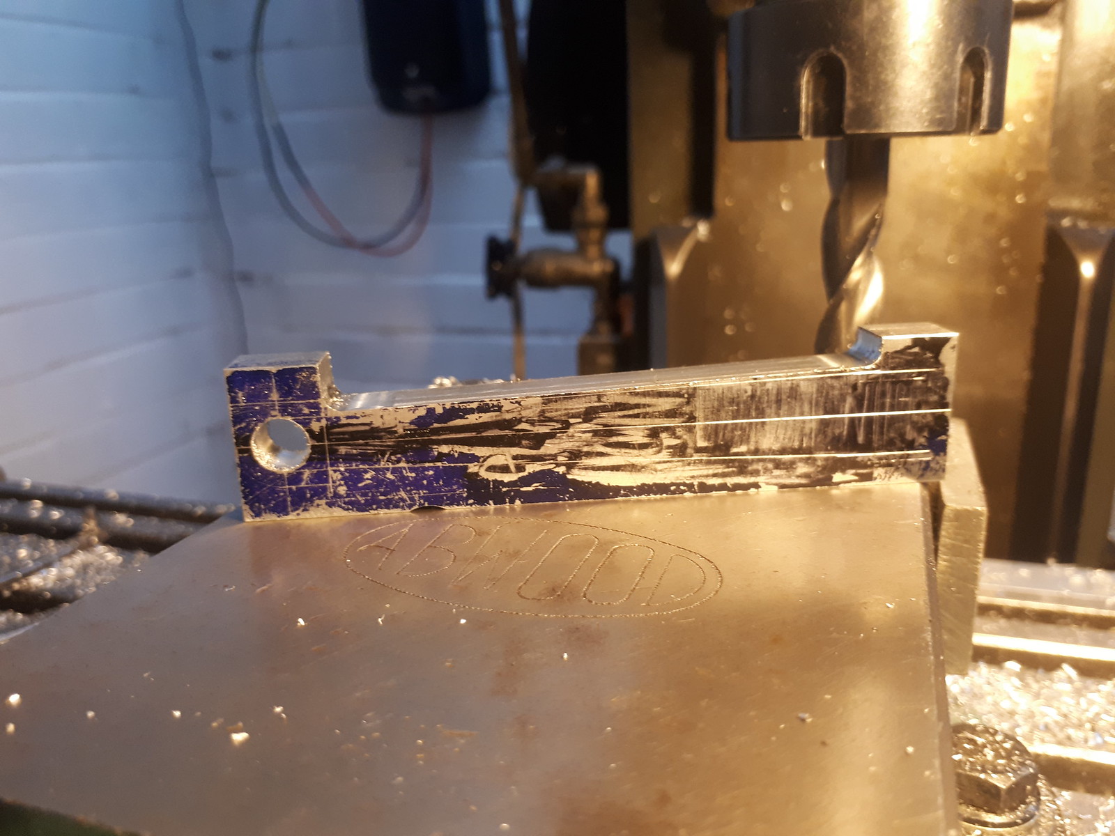
Setup using angle blocks in the vice.
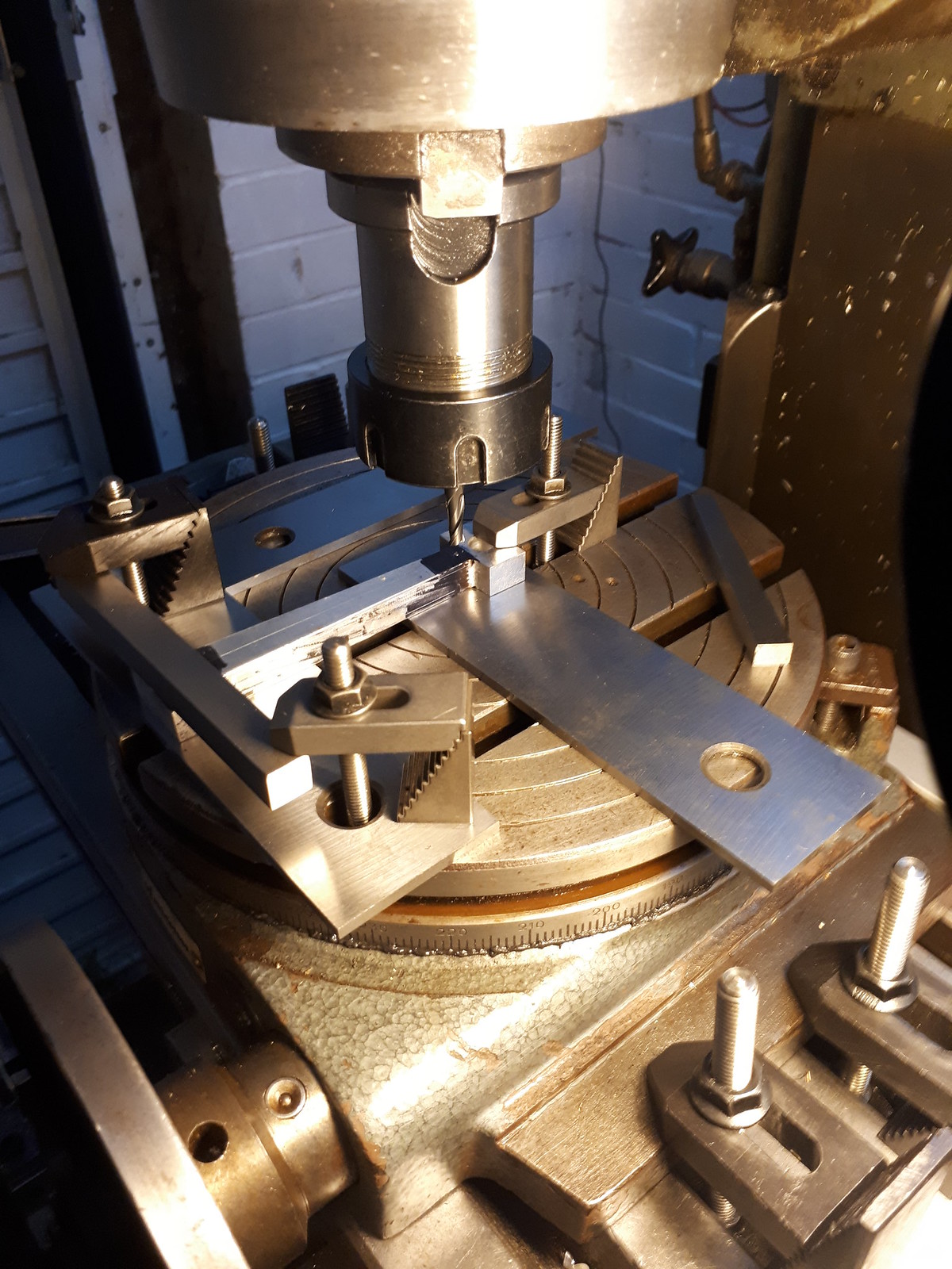
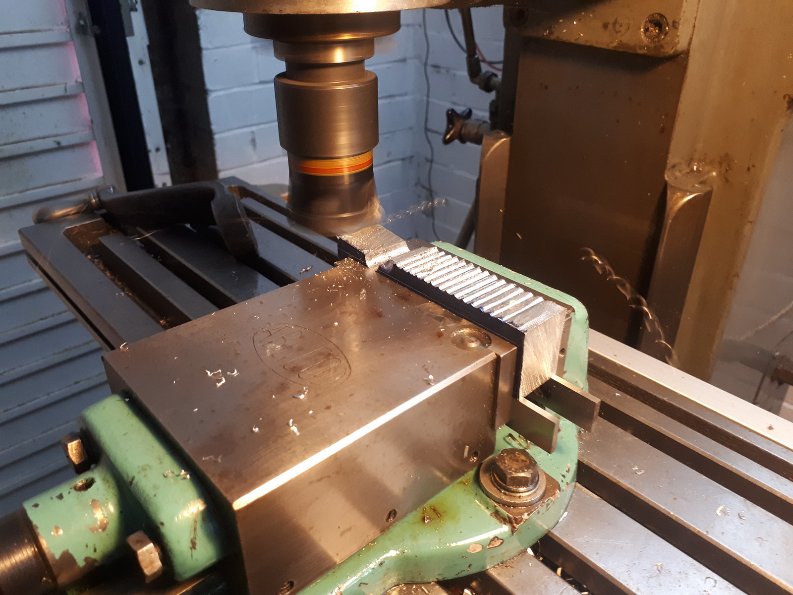
12mm end mill with 2mm radius.
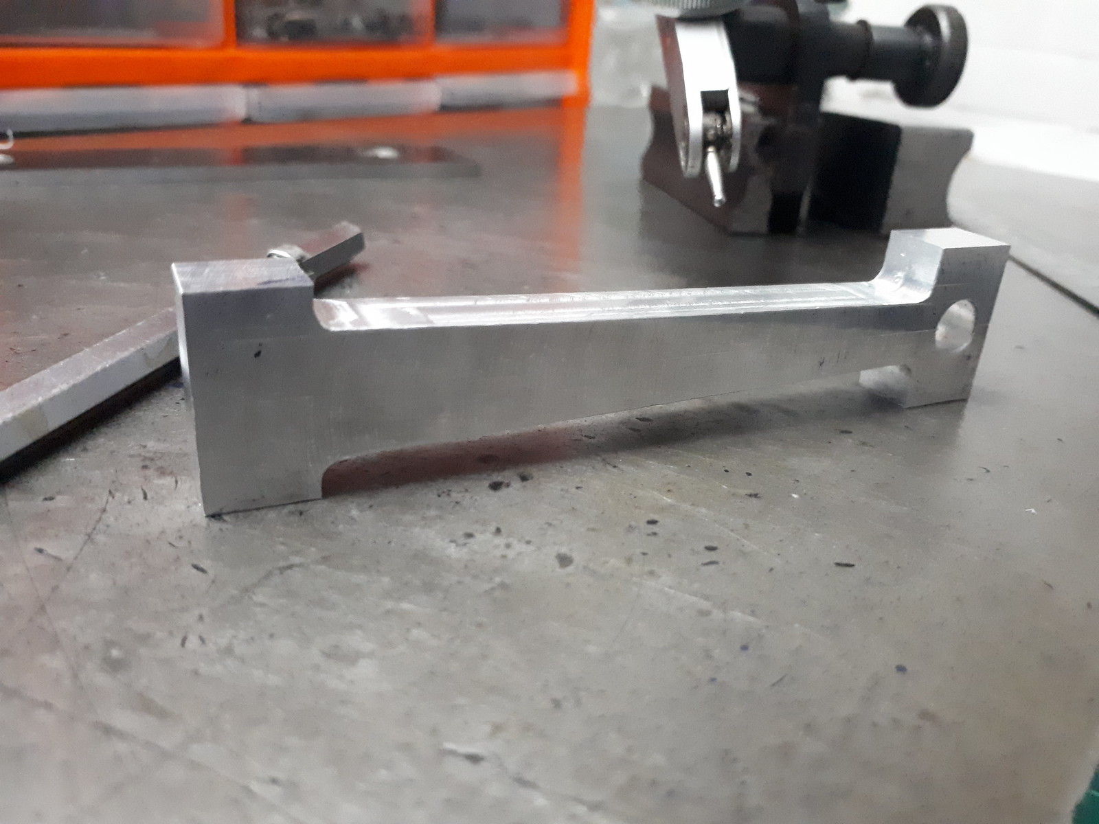
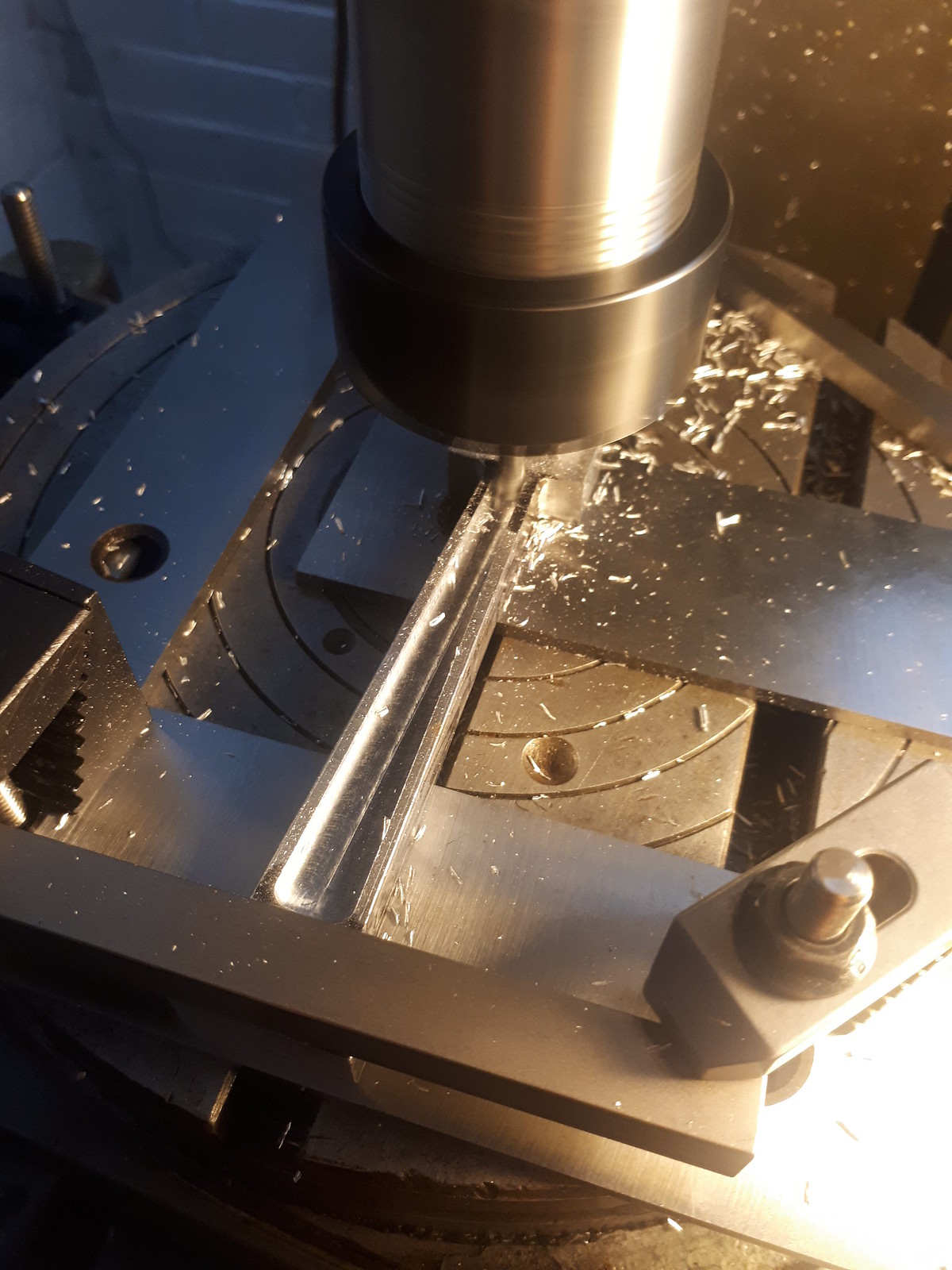
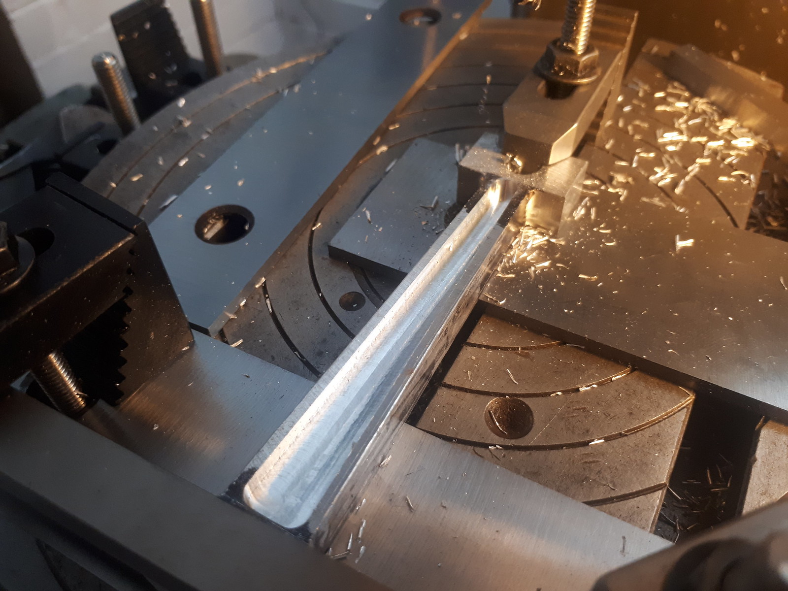
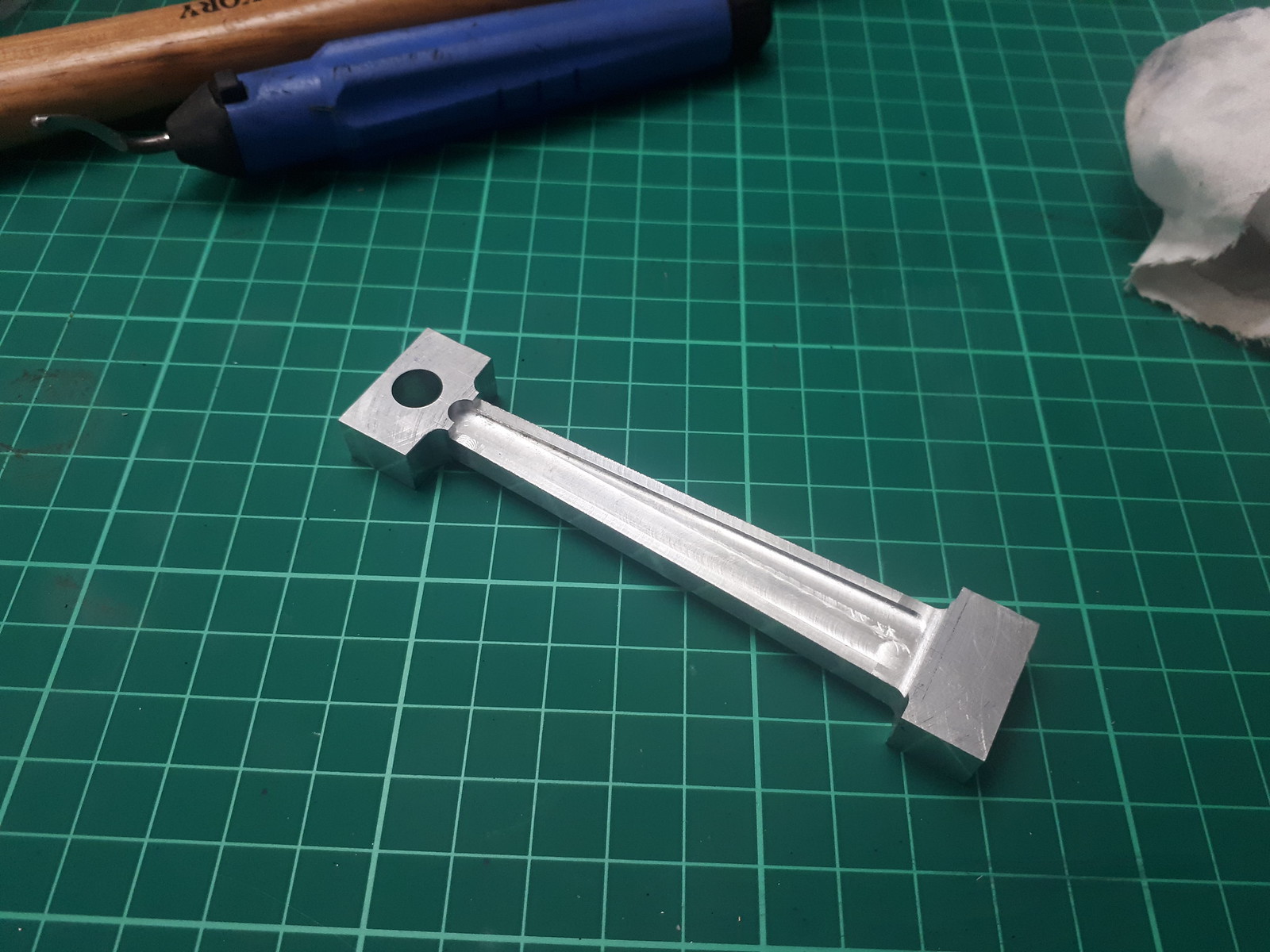
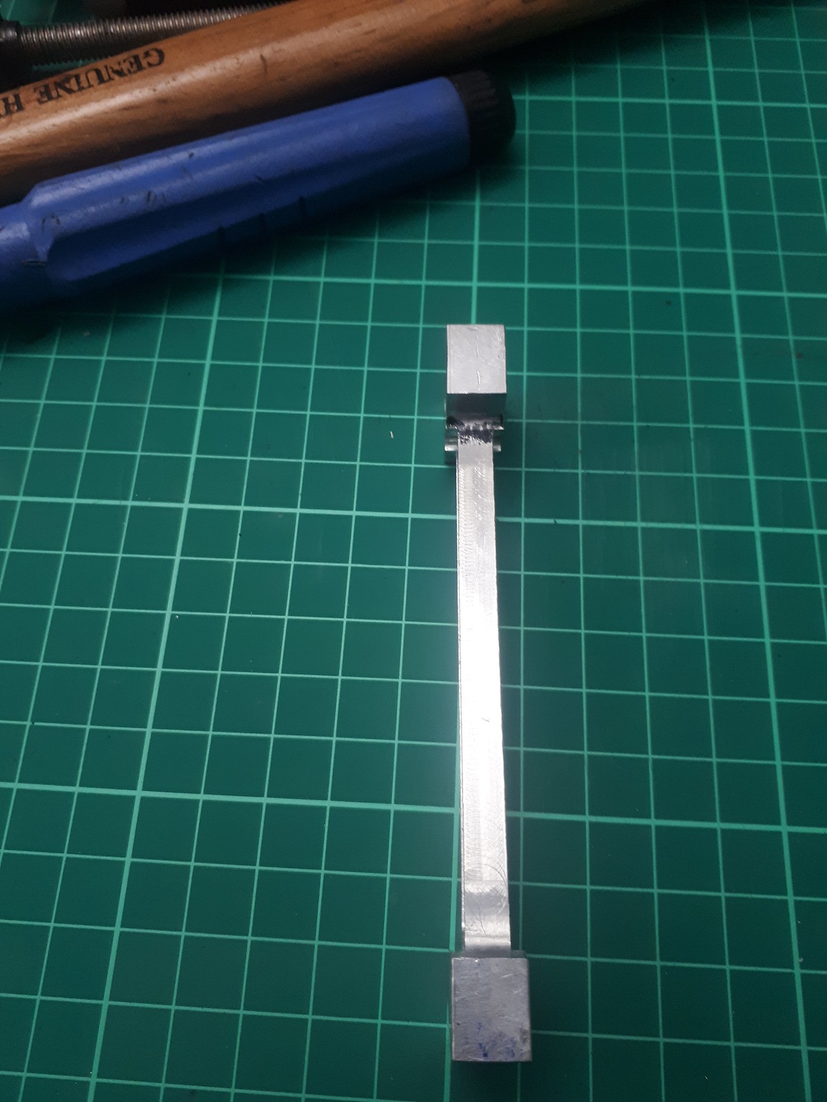
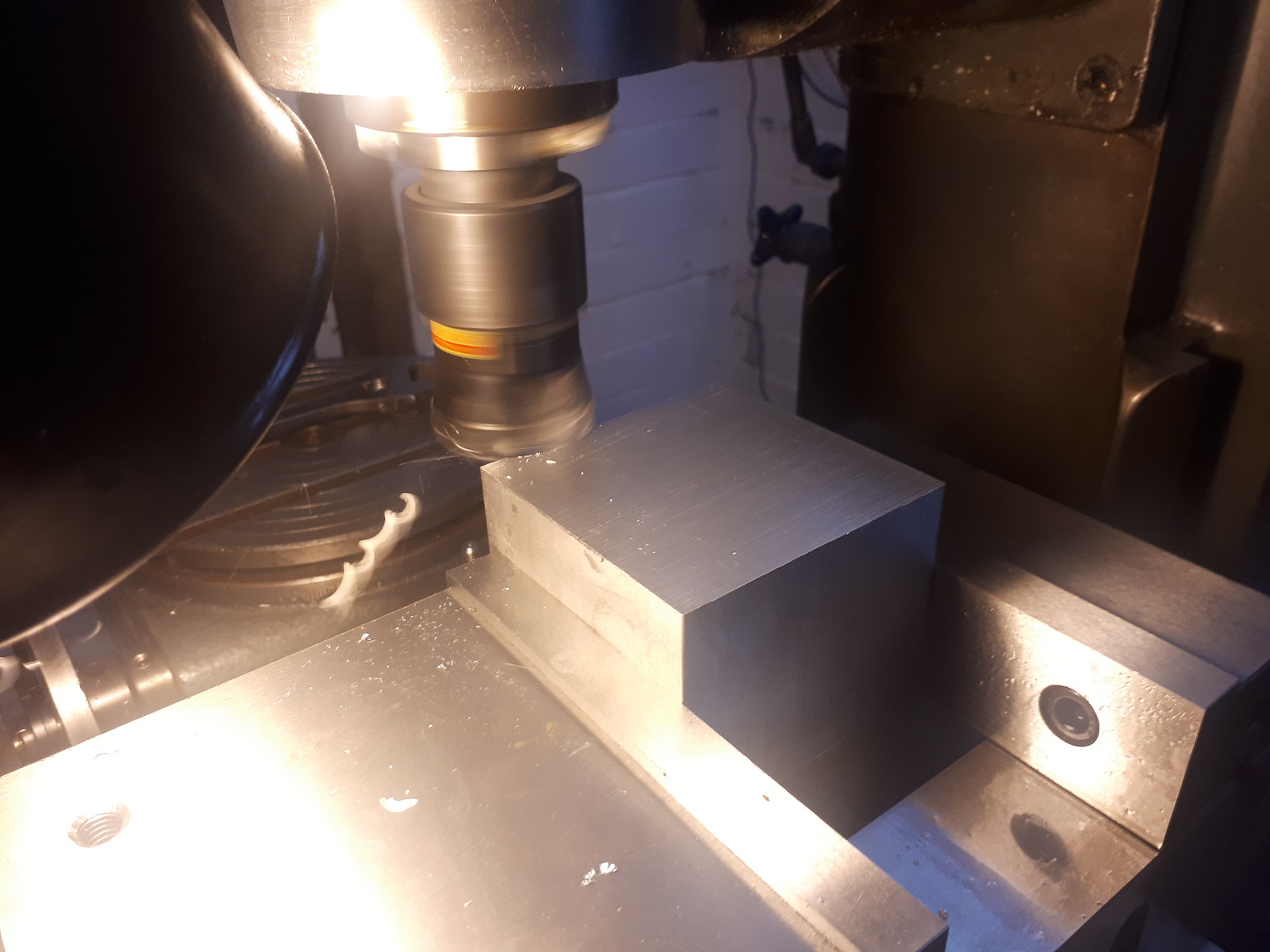
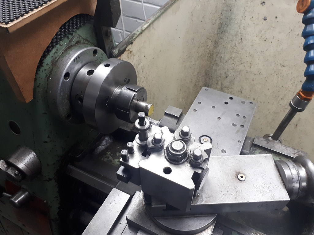
One side finished - a little bit of meat left on unintentionally. The depth of cut was determined using the marked line, with the setup and DRO allowing me to just flip it and cut the opposite side identically. I will keep the flats on the little end cutting the radius as the last operation to allow a reference baseline that spans the work piece.
At this point my battery powered garage decided to give up, which where I leave this until next time.
Thanks for reading - my format will probably change as I progress, maybe less words maybe not.
Earl
Some of the main stock materials laid out. Flywheels not yet purchased, some brass still to buy and crankshaft materials depending on which route I take to construct/machine it.
Whilst I wait for my 6" vice to arrive I decided to start work on the connecting rod. Laziness pushed me down the path of hogging away an pretty oversized piece of 2014A down to the correct size. Maybe I should make a power hacksaw first...
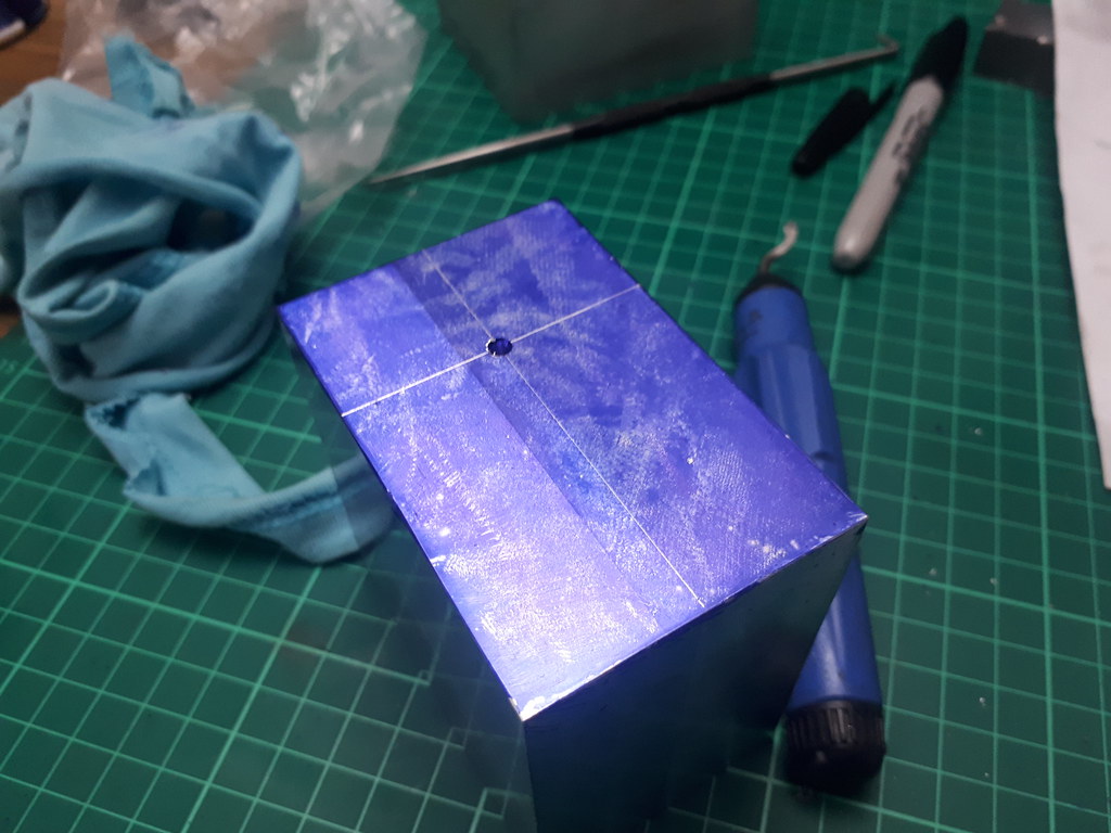
I will be making all critical cuts using the DRO but I still like the reassurance marking out gives. Some of the critical sizes marked, along with the lines to cut the angle between the little and big end. Difficult to see granted due to the Dykem not adhering too well to the machined surface (maybe some contaminants)
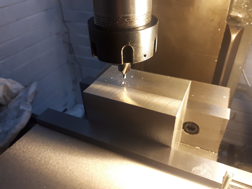
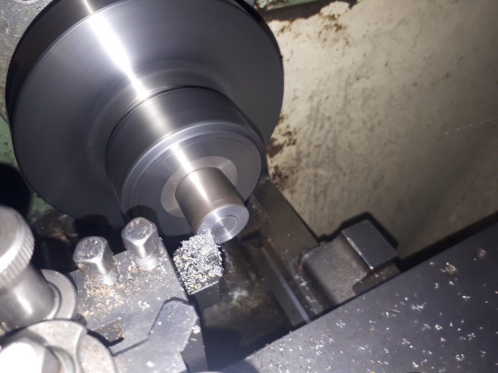
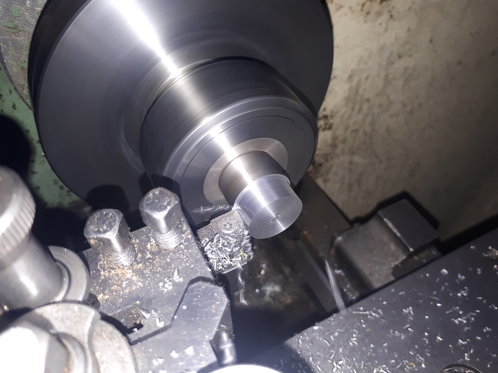
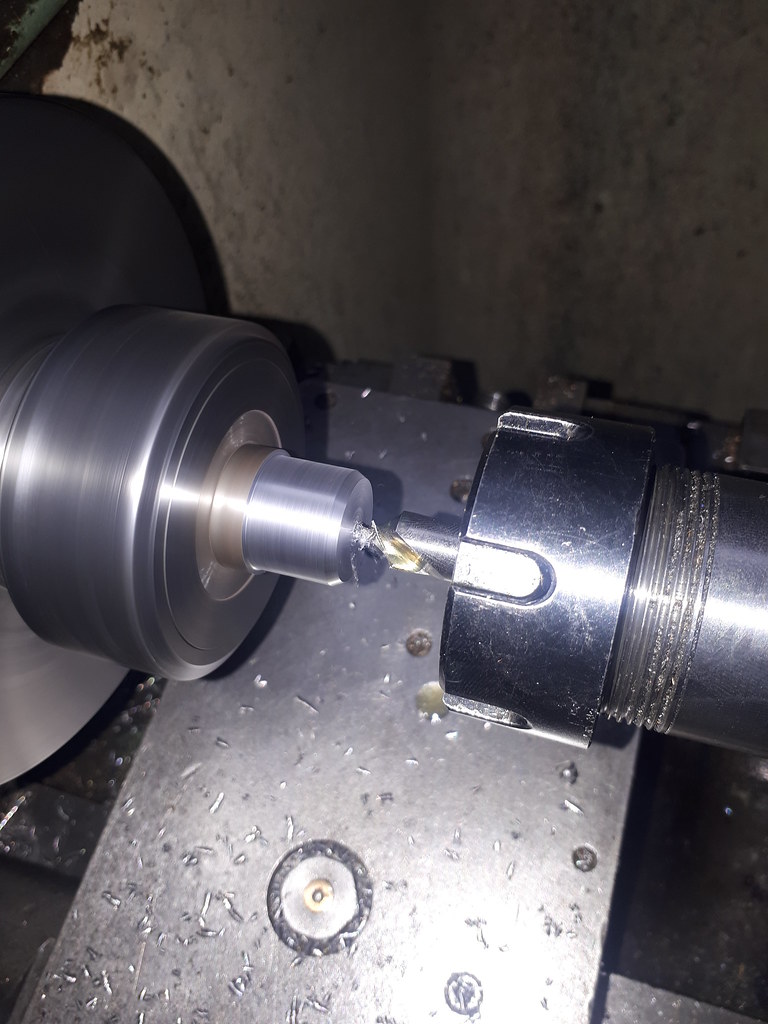
Never got any photos, but setup the piece in the vice, shaved a few thou off the big end flat and then wound up the 3.9" to the little end. Drilled, then reamed for 8mm.
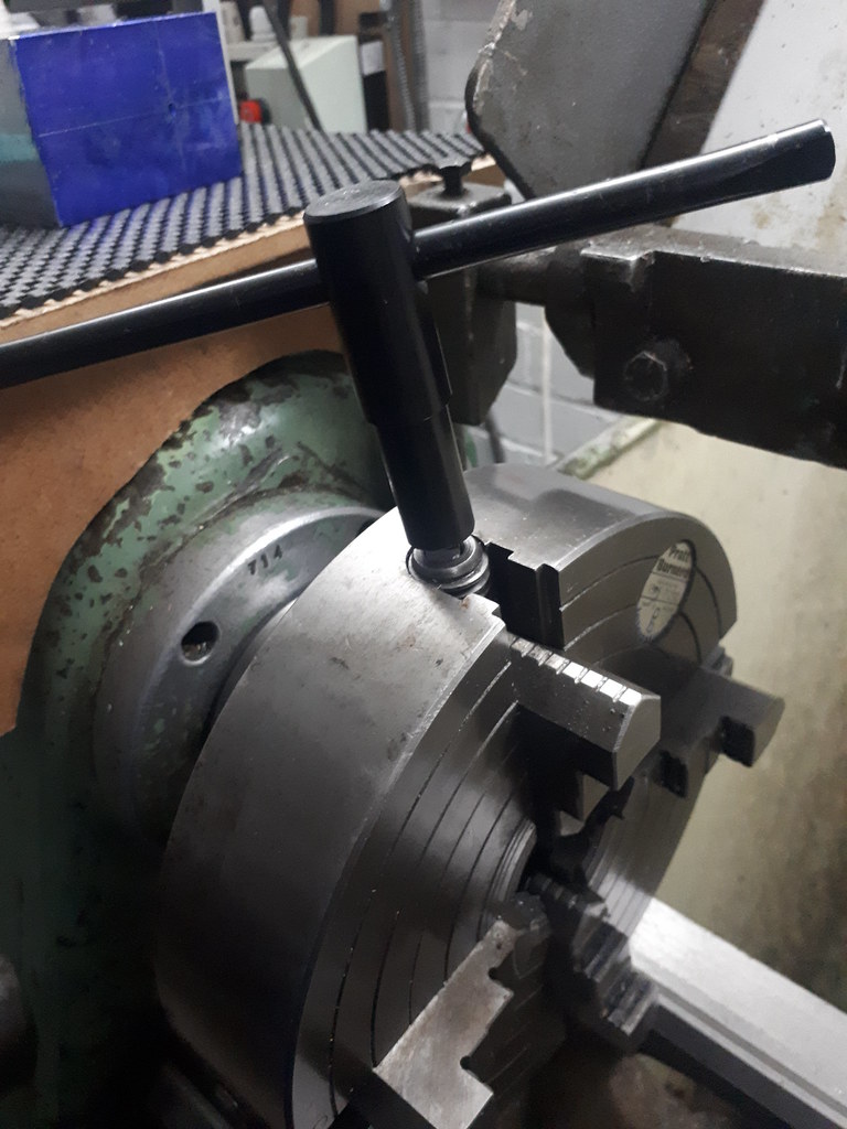
Setup using angle blocks in the vice.
12mm end mill with 2mm radius.
One side finished - a little bit of meat left on unintentionally. The depth of cut was determined using the marked line, with the setup and DRO allowing me to just flip it and cut the opposite side identically. I will keep the flats on the little end cutting the radius as the last operation to allow a reference baseline that spans the work piece.
At this point my battery powered garage decided to give up, which where I leave this until next time.
Thanks for reading - my format will probably change as I progress, maybe less words maybe not.
Earl