Best approch for machining a small flywheel?

Home Model Engine Machinist Forum

Help Support Home Model Engine Machinist Forum:

This site may earn a commission from merchant affiliate links, including eBay, Amazon, and others.

Hauk

Well-Known Member
Joined
Sep 13, 2010
Messages
47
Reaction score
0
After a long break from any serious machining due to an epic crash (in my book at least) I am ready to have a new go at the job that ended so badly.

What I was trying to machine was this flywheel:

flywheel.JPG


I am trying to come up with a procedure that in the end will give me a flywheel with as little runout as absolutely possible.

I have access only to a regular 3-jaw chuck. I have collets up to 12 mm.

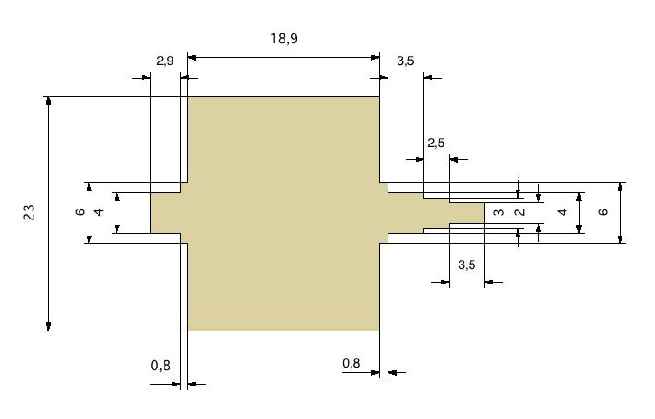
My plan is to start with a 25 mm diamer brass bolt and chuck it in the 3 jaw. It should be fairly easy even for me to machine everything to the right. As the flywheel is rather short in relation to the diameter, I plan to do this without support from the tailstock.

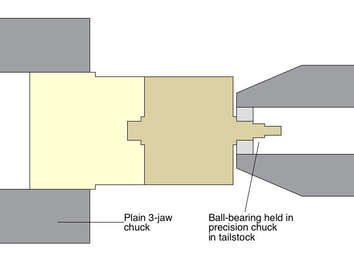
But what puzzles me is how to approch the short 4 mm diameter ball bearing axle to the left. I can not for the life of me figure out how to do this without having to rechuck the part after parting it off. The size of the flywheel in relation to the diameter of the axle prohibits turning the axle without support of the tailstock. But at the tailstock end I have just a feeble 2mm axle sticking out, so to me it seems like using the tailstock is no option.

And if I have to rechuck the part, is there any chance of getting acceptable results with a three-jaw chuck?

I would be very grateful for suggestions on how to approach this!

Best regards,
Hauk.
 
Clock it up using a Dial Test Indicator like this

100_2385.jpg


Stew
 
If the 4mm section on both sides is for a ball bearing then you could install the bearing on the first side and use the tail stock chuck to hold the bearing OD for support to turn the second bearing mount.

I would turn the second section a bit long to use a hacksaw to part it off then face it to length.

Dan
 
Hi Hauk

Have you considered making it an assembly? - as in turn the 23mm diameter x 18mm long section as one piece with a 6mm hole drilled/bored/reamed through, and a bit of rod turned down to 6mm with the necessary steps for the bearings and so on to press or "Loctite" or solder into that?

That might be a whole lot easier to do, as the 6mm section could be done in one machining setup without the heavy flywheel bit presenting problems.

Just a thought :)

Kind regards, Arnold
 
Wot Arnold said!


Additionally, I would clock it up like Stew said and turn one end leaving the small diameters a little long so you can put in a center hole.

Flip the part, clock on the OD and turn the features on the other side.

Now grab the end just completed in a true running collet so it doesn't get marred, and support the other end with a TS center and turn the OD down to 23mm from 25 mm.

Now , if you can , put some tape over the finished OD and chuck up in a three jaw and face the long end back.

There's probably 47 other ways to do this that I haven't mentioned..... ;D

Dave
 
Hi Hauk

Wot Kvom Said

you can still end for end it, without loss of accuracy - then there is no "turning on the left site"

KISS (Keep It Simple Sonshine)

Start with a blank 45-50mm long
make an extension on the 4mm end an extra 15mm long x 10mm dia., to make room for the drive dog and center hole.
After you have the correct shape between centers, use the 3 jaw chuck to hold the body to part off/face off the two shaft stubs and remove the center holes.

There are probably better ways I haven't seen yet but for now I would attack it this way.

Cheers

Bez
 
Well...that end shaft is only 2mm diameter....kinda tiny.

Could do them last I suppose and do it all between centers.

Dave
 
I would find stock that would allow the 23 mm OD to be machined back to a length of 30 mm.
After the first end was done, I'd flip it around and chuck on 10 mm of the 23 mm OD.

Put an indicator on the extreme end of the 23 mm fit away from the chuck and bump it with a
small, soft, dead blow hammer until the indicator reads absolute "0" the whole way around.
It is going to make some marks on the finished 23 mm OD but they will polish out easily enough.

Then I'd cut the opposite end fits to finish.

I have thrown plenty of parts out of lathes and boring mills in my days and I'm getting too old
for that brand of excitement.

You do not have to sacrifice safety to for accuracy.

Rick


As an ex-Automatic Lathe man - I would try to machine the thing in one go.

Machine the OD and long front end finished - then using a relieved part off tool work the back end down in stages - assuming you use a 3mm blade you are going to need a groove about 8mm wide, work your way down to the 6 diameter (non-critical I presume) - get that and the length of the big diameter (face) finished then work your way down to the 4 diameter - this is going to be tricky only because of measuring - use a vernier (suggestion) "calibrated" to the same diameter (which you have checked / fitted) at the front - then partially part off (not fully its going to fly away) - hacksaw off - turn around and face (not concentricity critical) - bingo - absolute concentricity gaurenteed.

Use the carriage lock and work the compond slide to the dials (keep measuring) - take very light cuts when facing the large diameter down to 6 diameter.

Alternatively leave the rear 4 diameter oversize for second op in a 4 jaw (which I think you don't have) - concentricity as good as your clocking.

For safety reasons a live centre would be advised - but even without it I don't think it will present any problems as long as you don't try any heavy cuts. Its surprising how little material is needed to "work" a job - but be careful.

I would definitely do it this way.

Nothing wrong with any of the prior suggestions - particularly turning it between centres as this will allow you to turn the job around without loss of concentricity.

Arnold's suggestion of a hub on an axle gives the added benefit of a steel axle.

Regards,
Ken

turn.JPG
 
Thanks to all for taking the time to help a newbie! I really appreciate it.

Ken: How would you support the flywheel when working on the right stub? To me it seems that Dan´s suggestion to install the ball bearing (he was right about that!) on the left axle is a good idea. I have a very precise drill chuck for the tailstock.

Rick: I might try your approch as well. To avoid marks, could you add a strip of paper around the part? Or will this compromise safe holding in the chuck?

Another thing I am a bit uncertain about, how hard should you thighten a three-jaw chuck? Is it possible to over-tighten?

Regards, Hauk
 
Hi Hauk

Generally speaking, if you avoid the use of a cheater bar on the chuck key, you won't hurt the chuck. But it might marr the work!

Like I and others have suggested, shim stock, like pieces of aluminum roof flashing work real well, under the jaws go a long way towards preventing a marred part. The other thing to consider is the thickness of a part. This part is pretty solid, but a thin ring would not do well in a 3 jaw if you tighten it down via the "2 grunt " method as it will deform the part into something that is more triangle shaped than round.
Hope that's clear.....

Dave
 
Haulk,

if were to make such a flywheel, I'd finish the external diameter and the 4mm ball bearing axle, leaving it longer than needed.
Then, having it reversed in the 3jaws, I'd rough out the other axle and switch to a collet to make the (very light) finishing cuts.
But I never tried, so I cannot tell You it worked for me.
Sure, when I machined the external of a 4" flywheel holding it by its 12mm axle I had problems.

Brass or aluminium shims will prevent marring the finished surfaces.

As for tightening the chuck: one only hand on the stock chuck key is enough for me.
Long workpieces must be supported. They will move however hardly tightened. That, I know for sure.

Marcello

 
Hauk,
Using the bearing in the tailstock instead of a live centre is a good idea if you don't want to use (don't have) a live centre. But it might cramp your style having the tailstock etc that close.

Since you only have a 3 jaw, doing it in one go is the way to go to get concentricity (I have a 3 and a 4 jaw and I almost never use the 3).

I'm not in the least concerned with that amount of overhang - as long as you don't go nuts on depth of cuts - this is brass but even in steel I wouldn't have a problem - you are working close to the chuck and the front bit is already machined and perfectly ballanced - so its not going anywhere.

The only "risky" manoever if the reverse facing of the 23 diameter down to 6 whilst it is only supported by the 6 diameter - like I said - light cuts should present no problem.
If you are unhappy add the centre or the bearing but personally I wouldn't bother.

Don't even think about revisitng the front end once you have started at the back - that would be a problem.

Like I said earlier the only trick part is getting the 4 diameter correct to size you obviously can't trial fit anything but you can use your forward 4 diameter as a reference.

Paper as an anti-marring device works well (I often use it on steel but not Aluminium or brass) - but as Steamer suggested aluminium roof flashing is excellent - but you are only going to need that if you turn it around.

If anything the part is less likely come out with paper added - the forces are the same and the friction is generally higher.

Personally I don't rate the chances of good concentricity 2nd opping from a 3 jaw as very good. That would be my last choice as far as options go.

How hard do you tighten a chuck ? - like Steamer said it depends - on solid bar which is at least as long as the jaws - just tighten it - as long as you are using the original chuck key, you'll give up before the chuck or barstock does.

When dealing with fragile pieces, tube or finished OD parts you don't want dinged then you need to be a bit more judicious - and if you don't tighten fully - then make allowances for this in your depth of cuts etc.
Also if you don't have the full length under the jaws, don't overtighten - its bad for the chuck - will eventually become bell-mouthed - same cautions.
If you must grip something with just the jaw tips place a short piece of the same diameter at the rear of the jaws (or a head on your backstop is a lot less fiddly if you have one) - holding something in the jaw tips is dicey to say the least - experienced turners will do it - but don't ask them how many times they've thrown a part - how do you think they got "experienced".

Ken
 
Hauk,
I was going to suggest a steady rest for end support, but you might not have one. They are often used for long parts that are longer than the bed. It is common to fit a bearing so the brass jaws do not leave a mark. I realized that you must have a chuck for the tail stock so I suggested that instead.

My thinking is the 2mm section is just too thin to provide any real support when turning between centers.

As Ken mentioned you might be cramped for space so make sure that the bolt you plan on using is long enough to get all the tools where they need to be.

These things are always a dance with the tooling and machines available for the job. I have several sizes of lathes and often one will work much better for the job on hand.

Dan
 
I agree with you Dan, As I mentioned, I would only go between centers for the final finishing cuts...and light ones at that.

Any run out from the 3 jaw could be taken out then.

Dave
 
OK, this is how i plan to do it (As I don't have steady rest or the means for turning between centers, those options are out):

I will chuck a 25 mm bolt in the 3-jaw, and machine everything on the right side.
Then I will press on the ball-bearing that will be mounted on this end. This bearing is a part of the design, so getting it off again is no concern.
I will then clamp the bearing in the drill chuck in the tailpost so it will act as a sort of steady rest.

Then the left side can be turned according to Dan's description. Since the right end is supported, I can allow myself some more space between the chuck and the part.

When the axle have the correct diameter, I will part off the flywheel with a hacksaw.

To finish the job I turn the flywheel, mount it in the 3-jaw (shimmed to avoid scratches) and then machine the axle to the correct length. As only the end is faced, a tiny amount of runout is not a problem.

Here is a sketch of how I plan to use the chuck in the tailstock as a steady rest:

Svinghjul_chuck.JPG


Have I missed something, or am I good to go? I

Regards, Hauk
 
Hauk,
That looks like a workable plan. Masking tape or any type of tape works good to protect a surface. I use electrical tape a lot because it is always in the shop.

Now I think you can see why a 4 jaw chuck is a handy item for second operation work.

Dan
 
Dan Rowe said:
Hauk,
That looks like a workable plan. Masking tape or any type of tape works good to protect a surface. I use electrical tape a lot because it is always in the shop.

Now I think you can see why a 4 jaw chuck is a handy item for second operation work.

Dan

Yep, a 4-jaw chuck would be nice. But how easy is it to clock up a part in a 4-jaw? Is it far easier than getting a part to run true in a 3 jaw?

Regards, Hauk
 
A 4 jaw is a learned skill....and a very valuable one at that.

I would embrace it if possible

dave


Latest posts

Back
Top