Beam engine at double scale--

Home Model Engine Machinist Forum

Help Support Home Model Engine Machinist Forum:

This site may earn a commission from merchant affiliate links, including eBay, Amazon, and others.
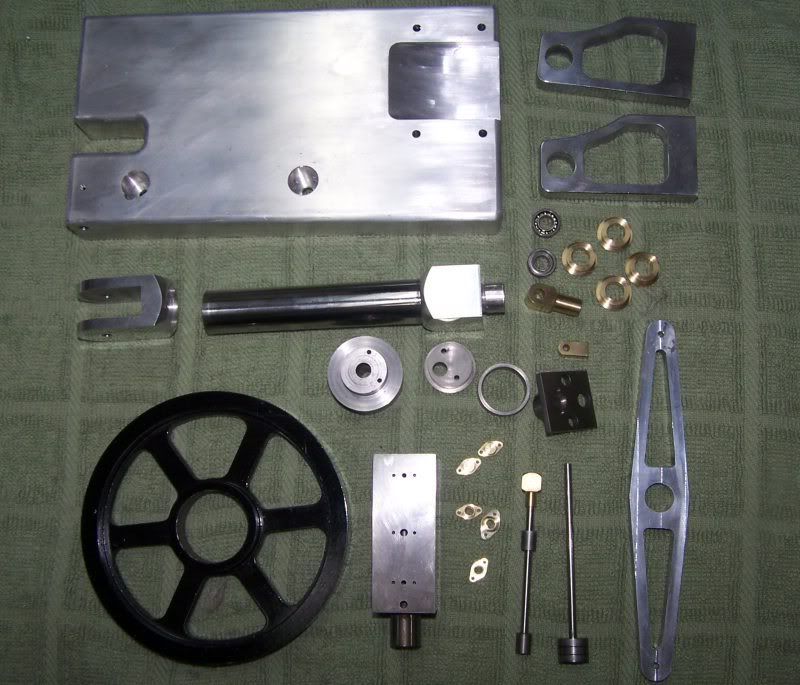
I have a question here about the operation of this engine that I can't quite get my head around. When I had assembled the piston/rod assembly and valve in the cylinder, but before I had any linkages hooked up, I tested the action of the valve by manually moving it back and forth within what seemed to be its usual limits of travel, to see what the piston/rod assembly would do. and it worked exactly like I assumed it was supposed to.--At one limit of valve travel, the piston rod stroked "out" quite forcefully. At the other range of valve movement, the cylinder stroked in---with a BIT less force, because some air escapes around the hole where the piston rod comes out through the cylinder head, and because the piston surface area is reduced on that side by the rod diameter. Last night I had the engine running quite succesfully on 18 PSI, when I made the video. Today, after I got my new silver solder I soldered some of the linkages that connect the valve, and this created an immediate "bind" situation. I then disassembled everything, and filed and polished the shafts, and after a couple of hours of "frigging" I got it to run again, but it takes 80 PSI to run it. While attempting to get it running again, I did a lot of playing around with the timing of the eccentric (which is really the only "adjustment" on it,) other than the length of the various linkages which I did not change. What I noticed was, that by adjusting the eccentric position I was able to determine when the power stroke (piston extend)started, relative to the crankshaft "throw" position, but I was NOT able to achieve a point where the piston rod retracted under power. Its almost as if my double acting cylinder is actually performing as a single acting cylinder, with power only on the piston extend side, but no power on the piston retract side. I know that my parts are all built exactly to scale, in terms of linkage lengths, etcetera, and I am just as sure that the original Elmers engine which I based this one on did run as a true double acting engine. Do you think that if I had the length of the eccentric rod (from center to center) adjusted incorrectly that it would cause this to happen.???? I'm at a bit of a loss here, and other than trying longer and/or shorter center to center adjustments on the length of this eccentric rod, I don't know how to diagnose this situation. Also, when the engine is running, I feel and hear definite pulses of air coming out the top of the cylinder head, which Gail says are caused by the upper end of the cylinder "exhausting"----however I do not feel or hear similar bursts of air coming from the hole at the bottom of the cylinder, which I assume would be the case if the cylinder was truly "double acting" and the lower end of the cylinder was exhausting.---HELP PLEASE.---Brian
 
Brian,
I am just leaving for a couple of hours, so can't do much right now.

What you are describing would happen if the eccentric rod is too short. The valve would not go up far enough to admit air to the top of the cylinder, so the piston would not retract.

Did you put set screws in cylinder block to plug the extra holes to the outside. If you can remove them, you can see the valve traveling past the holes. The linkage should be adjusted so the valve action looking through the holes is the same for both the top and the bottom.

If you don't have any luck, I will look at the drawings when I get back, but that won't be until about 11PM your time.
Gail in NM,USA
 
Gail---You were absolutely right. I lengthened the eccentric rod about 1/16" and it runs fine on about 18 to 20 PSI. That is a very delicate adjustment, and ---WONDER OF WONDERS---THE ENGINE NOW RUNS IN THE OPPOSITE DIRECTION!!! I didn't know that the length of that rod would have such a profound effect on the way the machine ran. It is very definitly running in "double acting" mode now, as there is a definite puff of air out of both the top and the bottom exhausts every time the flywheel makes a complete rotation. As a side note---That is rather a pig of an adjustment to make, because every time you want to monkey with the length of the eccentric rod, you have to completely unbolt the bearing stand from the base and dismount the eccentric rod from the valve lever to be able to turn either the end with the eccentric on it or the end that attaches to the valve lever.
 
Sounds like you sorted it out Brian... Seems like there is a great deal more to learn about these engines!

I will be looking back on this post when I come around to building a beam ;D


Ralph.
 
Hi Brian,
I am not familiar with your engine, so I might be offering a bum steer; check first!
Most valves I am familiar with have an adjustment on their spindle to allow them to be moved (within limits) closer to or further away from the crankshaft. It should be no more difficult than removing the valve chest cover, and moving a nut either side of the valve to move the valve one way or the other.
Regards, Ian.
 
Ian--I have it sorted out now, and running okay. there is no such adjustment on this engine---the adjustment is all in the length of the eccentric rod. If you look at the 3D cad model in the very first post, you can see what I was dealing with.---Brian
 
Brian,

During my fall quarter of vo-tech I essentially have a "free rein" to build anything I want during the twice-weekly shop classes. I'm leaning towards building this engine, as it has some aspects of machining I want to try out, and it can be completed easily within the time allowed. Couple of questions for you, or anyone else:

- Can I assume that the three .25" holes in the base are there for mounting it on a wooden base or other support?

- Is there an easy way to make the eccentric rod straight (e.g., by moving the eccentric outboard )? Seems to be doing so would allow its length to be adjustable by having left and right-hand threads on either end.

- Can I assume that the connecting rod is threaded to provide a length adjustment capability? I think machining the connecting rod and rod end as a single piece would be an interesting mod.

- The plans I downloaded all have dates of 7/24 or 7/25 (from Mediafire). Are these all up-to-date?

Other than some of the thoughts expressed above, I am planning to try a couple of other things that are non-critical to the design:

- The flywheel will be a 6-spoke using Marv's flywheel program for layout.

- The column will be tapered and fluted, using a technique I learned about in a magazine recently.

Should be able to get started n Oct. 2.
 
Yes, the three 1/4" holes are for mounting.
No, there is no easy way to make the eccentric rod straight unless you put an offset in the beam. If you move the eccentric outboard, there is nothing to keep the eccentric strap from falling of the outside edge of the eccentric.
There are 2 drawings that are not up to date--look back thru this post and you will see new drawings for the piston and piston rod---(I had the wrong thread on them).
Yes, the connecting rod is threaded to provide some length adjustment.
Good luck, and PLEASE post progress.

Brian
 
Brian.... Talking of progress, have you shined this big fella up yet?

Just wondering how that copper comes out? ;D


Rlaph.
 
kvom said:
If the valve lever were made wider by the amount of the rod's kink, could not the rod be straight?
Okay Kvom---This is what it would look like with a straight eccentric rod. This involves a change to the eccentric rod, to the cross shaft on the valve rod actuating shaft, to the base, and to the short shaft from the lever on the other end of the lever which the eccentric rod attaches to which connects to the strap which runs up to operate the valve.

engine with straight eccentric rod 3 views.jpg
 
Divided He ad said:
Brian.... Talking of progress, have you shined this big fella up yet?

Just wondering how that copper comes out? ;D


Rlaph.
No, no bling yet. My garage is full of customer parts that I have "reverse engineered" and I haven't even mounted my buffing wheels yet.---Brian
 
Brian,

Thanks for the picture. I would plan to make the connecting rod bits last when I have a partial assembly of the rest in order to verify fit.

I did quite a bit of study on the plans last night, and have some ideas to challenge myself. These include:

1) Eliminate, to the extent possible, visible drilled holes.

2) Avoid 90-degree edges. Chamfer, round, fillet, etc.

3) Make the beam link one piece

4) Make the connecting rod and end one piece

Others as I go along.
 
Brian,
Just so you know that I have not been completely useless the last month or so, here is a photo of some of the parts for my version. Most, but not all, have had just enough finishing to remove the tooling marks. I hope to get back on the project later today.
Gail in NM,USA
beam2x-1.jpg
 
Great pics Gail. I'm going to steal the ideas for the bearing stands and the 2-piece eccentric ;D

In fact, I don't see why I shouldn't just machine the inner part integral with the flywheel.

Having a "notch" for the lever as opposed to cutting it away also looks good to me.
 
The flywheel was made from a 2-1/2 pound cast iron weight lifting weight. Thats why it has a large hole in the center. There are a lot of different weights available, but most of them are difficult to machine because they are very poor grade of cast iron and have residual sand in the surface. They will eat up carbide tooling as fast as you can put it in tool holders. The BFCO ones are fairly good cast iron and are available from the REI sporting goods store in this area. They also have some junk (for our purposes) ones for the same price. The Walmart ones are no good also. I found one bit of voids in the casting. It showed up when I was roughing out the blank on the lathe and was small enough to locate inbetween spokes when I milled them out. Your mileage may vary.
beam2x-2.jpg

The hub for the flywheel was made of Cold Rolled Steel and the eccentric and eccentric strap were made of close grained cast iron. Notice that I put a flange on the eccentric. This goes away from the hub so the eccentric strap is captured between the hub and the flange with about .010 inch clearance. This is important with an offset eccentric rod as the eccentric strap will work back and forth sideways on the the eccentric as it alternately pulls and pushes.
beam2x-3.jpg

Gail in NM,USA
 
thats a great looking motor. And you did a great job on the flywheels as well hats off to you.
That beam engine your design or from plans. Where can i get a set. And thank you for flywheel leason. [email protected]
 

Latest posts

Back
Top