Bazmak-Making a turret/capstan for the minilathe

Home Model Engine Machinist Forum

Help Support Home Model Engine Machinist Forum:

This site may earn a commission from merchant affiliate links, including eBay, Amazon, and others.
Joined
Dec 12, 2012
Messages
2,220
Reaction score
1,285
Early days yet,but I have a question early.What gear size is the rack and pinion ?
As you all know thoughts start flying about in your head,started with a pencil and back of a matchbox.Basic idea at this early stage is to fabricate a tailstock carriage with top plate and apron similar to the main one and drive off the
existing rack with gears and pinion.If I can get right then I cn build up a
tool turret from there.If you read one of my earlier threads I converted a wood lathe to metal by fabricating a carriage with a central leadscrew.This carriage would not be much different or difficult.
The idea being a large 3 spoke handwheel to drive the turret thru 2 mod1 changegears (surplus to first lathe) to get the direction correct.I will have to make a new pinion as the original,hence the initial question I will replace the deleted photos and try to get them in a semblence of order. I will be unable to take new photos as i sold the mini capstan lathe and bought a Myford which i have on a current thread.I do however have all the original photos which i will repost if Mike makes contact or anyone else shows interest r pin 01.JPG

r pin 02.JPG

r pin 03.JPG

r pin 04.JPG
 
Last edited:
Forgive me but my Guessing Stick was handed to my son years ago and I've long given up my doodle pad which was a cigarette packet.
So I have to write what the history book says- and damn those critics about using the past as a suggestion.

Cleeve simply used the Empirical Formulae of using a rack from Myford proportions but after a series of earlier efforts on older m\achiness, skewed the feed. The rest of the panjandrum was fabricated.

I have a Mk1 Clarkson T&C but for the life of me, I've never explored but I made the baby one which is the Stent and later got a welded one. Clearly, there was a rack and pinion and it dawned on me that it was actually a Myford rack with a 20DP gear on both! I still have the fabricated little Stent and it works!

So Metric????. I had a 918( actually a 9180 with a Myford nose) and I have no doubt that it was a 3mm leadscrew and 1DP cogs.

So lashing it all together, I would say 'use what you have or can make'

Leverage is simple- make the lengths of the 'levers' to suit your personal equation.

Does this help, please?

Now I'm on the look out for a 3MM leadscrew and half nuts-- for a Myford ML10. Any bright sparks to help?

Cheers

Norm
 
Hooray for 'Pelmanism' for unearthing my old wartime schoolboy French, you want 'Tour en general- OneDrive' for various capstan configurations.

N
 
A thought, I have a turret that fits into the mt2 taper of the tail stock. Not a rack pinion drive but a start. I also have a complete turret sliding assembly, handwheel. Fits a Harrison M-300 . Can be adapted to fit others. But you need to have a lathe swing of 12inch plus.
 
A thought, I have a turret that fits into the mt2 taper of the tail stock. Not a rack pinion drive but a start. I also have a complete turret sliding assembly, handwheel. Fits a Harrison M-300 . Can be adapted to fit others. But you need to have a lathe swing of 12inch plus.

The Sparey I mentioned, fits into the No2MT tailstock- originally a Myford ML7 which swings 7"

The Ken Metcalf- I have the drawings etc somewhere- was designed for the ML7.
What has to be mentioned is the need to bore each station in line with the spindle.
So Baz has to really have something to 'line up' with his own lathe.

Don't be offended please- I'm simply clearing up possible misconceptions.
Or the reason why I have done nothing to mine- yet:hDe:

Regards

N
 
Thank you boys.I have seen the capstan attachments that fit the no2 MT
but don't like them + they will take up room on my limited 14" centres
As with the model shaper my memories take me back to operating the old Ward 7 capstan lathe and the good feeling of the solid clunck as the turret swung.Would like auto rotation but at this stage only have in mind manual
Initial thoughts were to make the carriage and rack/pinion drive first to
get it all working,before thinking too much about the turret
I thought that lining the stations up would be easy,just drill and bore from the lathe headstock when each position is set.Please correct me if I am wrong
Meanwhile just nipping out to get a few pieces of steel to make a start
Regards Barry
 
Well I have made a start.Hacksawed of a piece of 100x20mm HRS
11 mins saved me $6 cutting charge.Cleaned and sqared up all faces
and cut the 90oV with an endmill.Decided to get the fit much nearer before
doing any further machining,so spent an hour fileing and scraping till almost there.Took further very light skims using the V as a datum
Must say it was easier than i thought it would be and far superior to a cast oneapron 01.JPG

apron 02.jpg

apron 03.JPG

apron 04.JPG

apron 05.jpg
 
Last edited:
Well after an enjoyable 4 hrs in the shed I have finished the basic carriage
and apron.I made 2 no stepped gibbs and fitted.Just a couple of thou play for now,too early to bed and scrape at this stage.Also cut down and machined
a piece of 90x90x10 rs angle,also fitted.All fixings are cap screws from the top
so I have easy access for adjustment or dismantling.Now I have the basic frame the fun begins.Next will be the pinion.Will have to make one to the same dims as existing.I was going to use 2 mod 1 changegears to drive from the handle to the pinion,with 1 gear fixed to the pinion,but have decided to try and make the pinion and gear as one unit.The pivot shaft I have in mind to turn
slightly eccentric so I have adjustment for centres.Should be interesting but
my head is going round in circles.Thats what happens when you do a bit at a time with no drawings
 
Last edited:
Next I decide to make the pinion.After all those hours playing about with
gearcutting I am now reaping the rewards.Took off the rack and apron from the mini lathe and using a couple of different methods I measured the rack
at 4mm pitch.The rack was located on the mini lathe hard towards the headstock and had approx. 50mm unused,so redrilled and moved towards the tailstock approx. 45mm to give more use where its needed
Next I measured the pinion and came up with 11 teeth and mod 1.25
Decided to make the new one 12 teeth for obvious reasons and turned a piece of stock up to the new dia and over long.Ground a single point tool to the rack profile and proceeded to cut the teeth.Easy peasy started with half millimetre cuts and finished at quarter mm.No problems lovely finish.Full depth 2.8mm
Then raised the cutter 1 pitch and took a single pass on each tooth.Then lowered the cutter 8mm 2 pitches and cut again to give the involute form
Looks good and seems to work on the rack,but now have to finish the pinion
and mount to check centres and working etc Another day,but very happyView attachment 94705

View attachment 94706

View attachment 94707
 
Last edited:
Finished the pinion and press fit a 35t mod 1 changegear.Made and fitted
a pivot pin to a 6mm hole in the apron just as a trial fit.Had to pack the
apron 20 thou and run a needle file over the pinion teeth.Knowing I was out by 20 thou in the centres I drilled a new 8mm hole over x 30 thou with an end mill
then made a new pivot pin.Runs well at this stage.Then bored and bushed the apron for the handle/drive gear.A nom 60t spare mod 1 change gear.Next to make a 3/4 arn handle and shaft before setting everything up to run smoothlygears 01.jpg

gears 02.jpg

gears 03.JPG
 
Last edited:
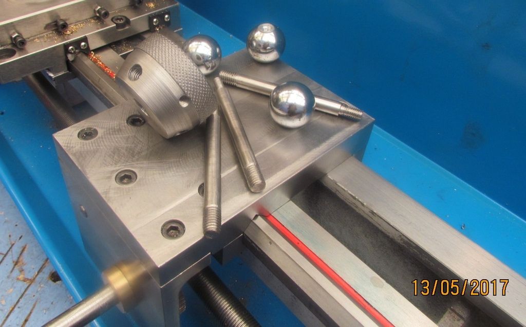
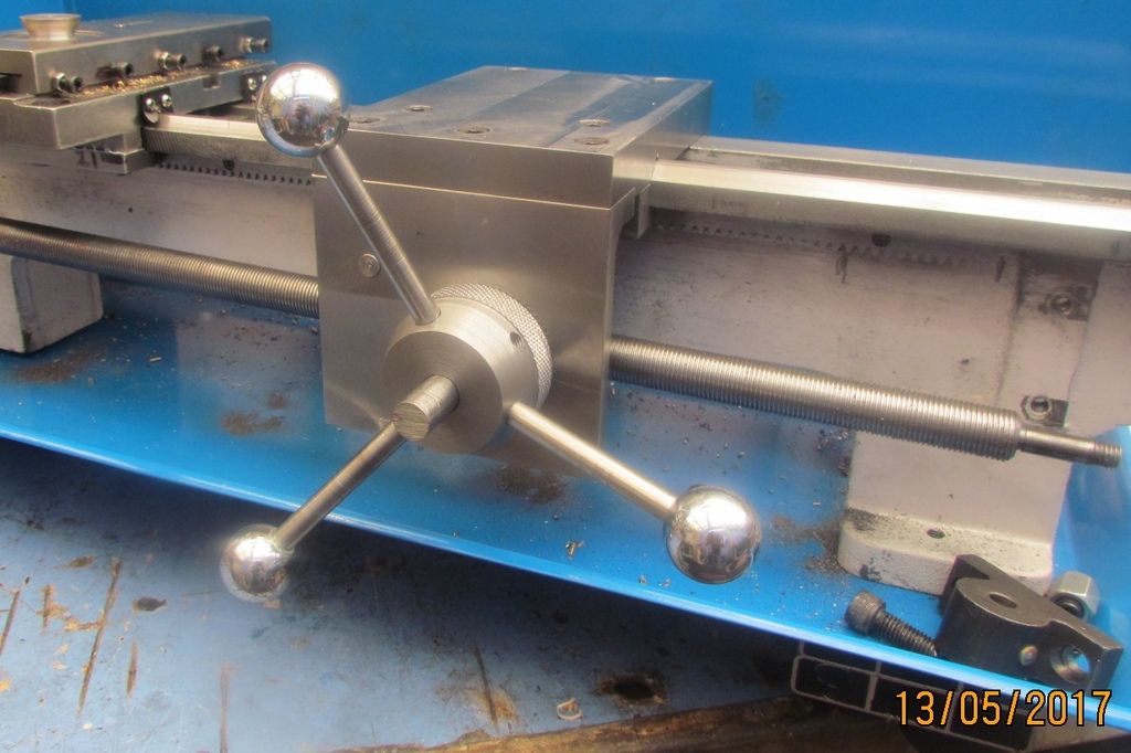
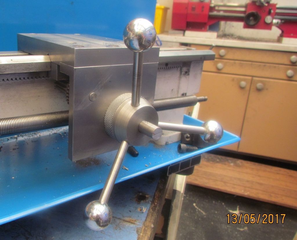
I first turned the drive shaft and fitted the 60t gear,light press fit and key
Made the central boss from a piece of 50 dia mild steel.A short piece of
knurled bar from test piece of knurling thread.3 arms from 8mm stainless steel
and 3 no ball ends.All went together well and works a treat.Now to start turning my thoughts to the 6 station turret,while I tidy this up and bed in
all the slideways etc.Must admit it looks good and feels good
Here are my thoughts please comment or make suggestions
6 way turret round or hexagon ?
had in mind to fit a dovetail slide to the top plate in line with the lathe axis to give more movement/adjustment
and to help take up some of the height.Lathe centre height is 91mm
used 20mm for the top plate.I plan to make the turret 50mm high with a 10mm
plate under to fix the ratchet/stop for the station
So that gives me 91 c/ height - tp =71mm - 25mm turret =46mm for combined
dovetail slide and turret bottom plate.Also have in mind to bore out all the stations and fit top hat collars locked with std gudgeon type pins
Each collar + spares can then be fitted with small drill chucks and collet chucks for drills taps reamers etc Also a die box and maybe a chasing box
Cant really envisage needing it to make large quantities of small items but
who knows maybe brass thumbscrews
 
I stripped everything down again,blued and scraped the top plate,finished a few details,set and greased and off we go ready to build the turret assembly
Few tight spots,down to the lathe ways.Need to get a couple of thou of the underside of the ways at the headstock end.Also later I will make a new piniom
pin with both diameters offset by 1mm eccentric then I have adjustment to
take out some backlash from the rack/pinion.Ready for phase 2.Short video to show motion https://youtube.be/Xtncwb2bfpw
 
Again I got the link for utube video but it doesn't seem to work DOH
Look on utube search capstan turret attachment for mini lathe
 
bazmak,

Some thoughts I have (You did ask.) Maybe too much, but what the ...

I like the idea of collets to hold tooling. ER series?

Each "station" mounting some type of quick-change? that can be indexed in some way so that orientation does not have to be reestablished on changing tools.

Some type of one-step advance from one station to the next, either mechanically or with a stepper motor?

A station on the turret for drilling done somehow: If you went back and added an indexing feature to the chuck/headstock, you would have a great way to make bolt-hole circles (I.E.: a flange or nozzle) on a turned part while still in the chuck.

I admit to wanting to see you build the mouse that turns into an elephant, but I find this project just as interesting as an engine build.

--ShopShoe
 
Thank you shopshoe,what I have in mind is this.Simple ,not too complicated
after all all it only a mini lathe no 2, so its only for playing about with.
I propose to make a cross slide at 90o to the table in line with the axis of the lathe Nom 100 x 20 flat same as the table top,lockable with nom 50 mill adjustment to take up differences in tooling length and reduce centre height
to nom 50mm. 2no 100mm discs would then be mounted, 20mm and 60mm thk.
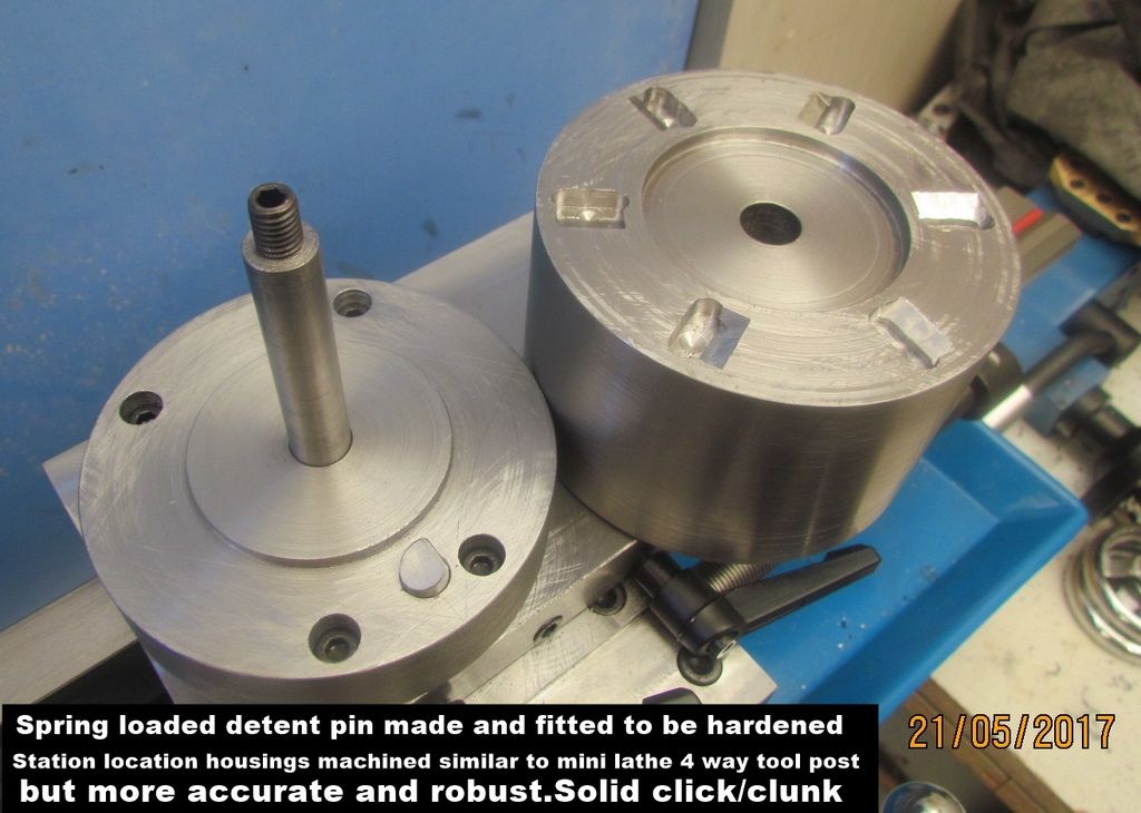
The lower one fixed to the compound slide and to house the ratchet for locating the turret stations.The 60mm one will be the turret to spin and locate each station with a spring loaded pin similar to the 4 way lathe tool post
but more accurate and robust
When that is done and each station confirmed and locked and everything in situ I can then centre drill each station from the headstock to give a location for milling the flats and boring the turret.Each station to be bored say 40mm dia to hold top hat tool
holders.These will be clamped with gudgeon type pins as typical capstan lathe
and can be bored/threaded to accept chucks/collets and special tooling
I will make a couple of ER32 and ER16 collet chucks to suit my collet sets
Already looking for small compact keyed Jacob style chucks etc etc
Thank you for your comments,most welcome any more greatly appreciated
Like most things this is evolvlng as I go along
 
Bazmak,

That sounds doable. Thank you for the explanation. I was having trouble visualizing the orientation of the top-hats and how that would work.

Good luck and waiting to see what you do next on this project.

--ShopShoe
 
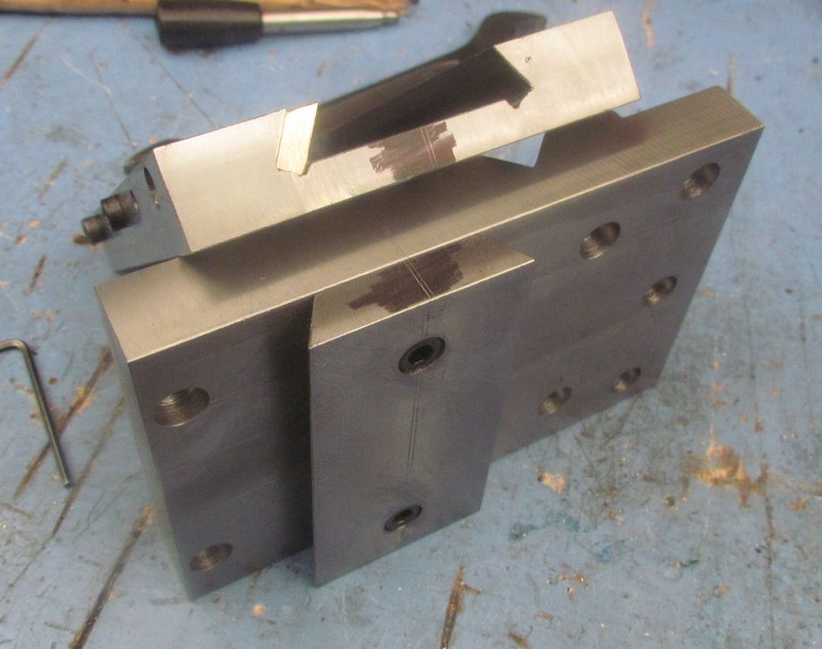
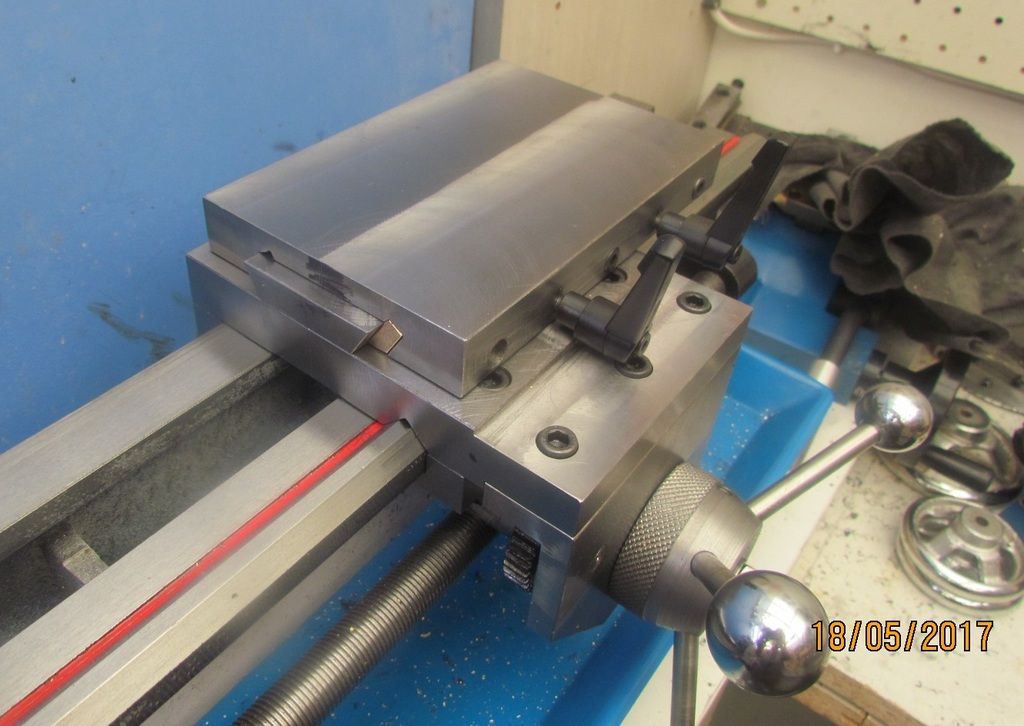
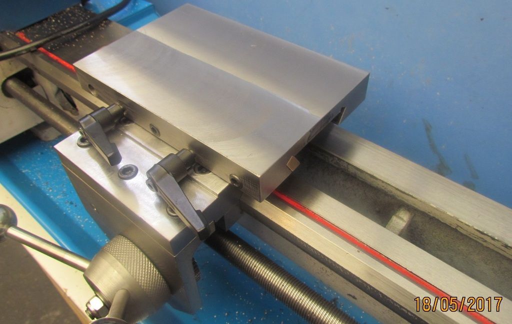
Well I hacksawed another piece of 100x20 flat steel x 150lg.Cleaned up in the mill and cut a 50 wide x 11mm deep female dovetail.Made a male dovetail
and a brass gib.Fitted and assembled.Works well.Onlu fly in the ointment
I broke an M5 tap and don't think it will come out.Its not doing much so
will probably dummy the hole with a caphead .Just had 2 slices of 100mm dia cut ready for the turret.Paid $12 cutting charge but better than a hacksaw
Starting to look good
 
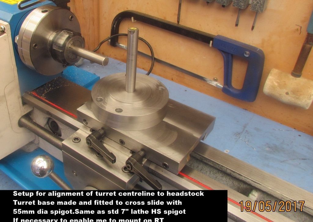
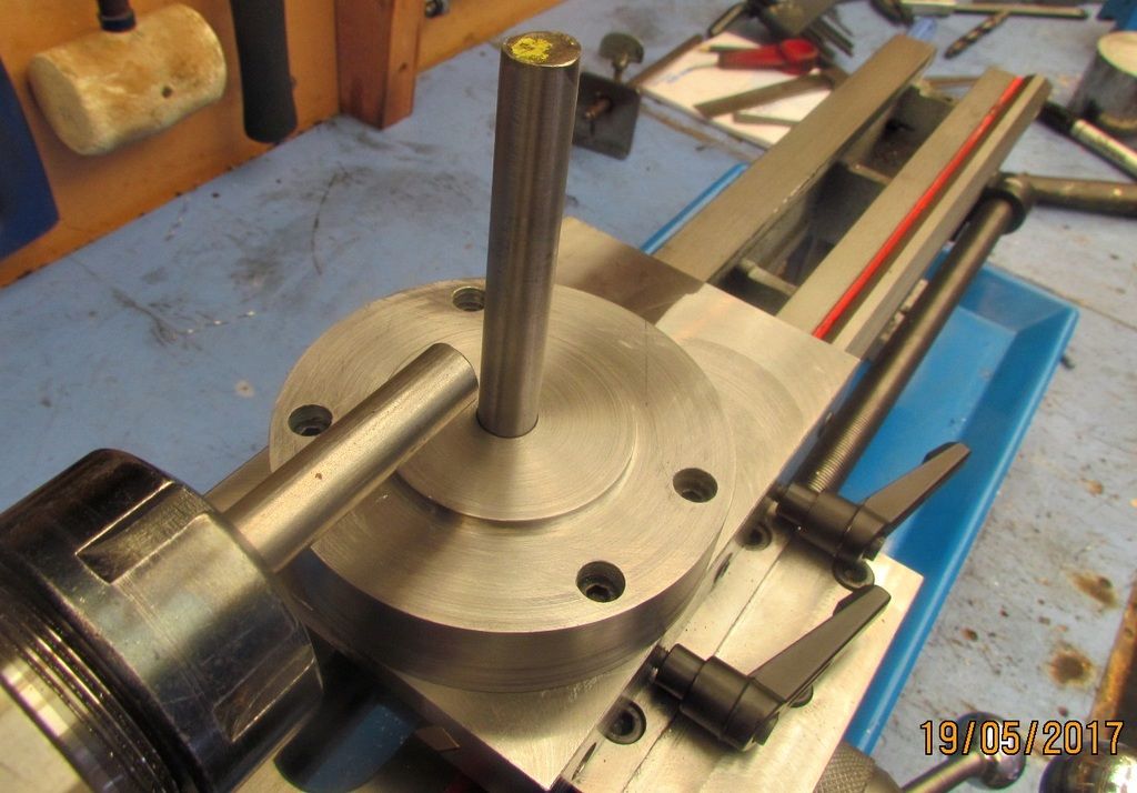
Made the turret base from a 25mm slice of 100mm dia mild steel
Made and fitted a 12mm dia shaft and turned a 55mm dia location spigot
the same as the std main spindle housing on the std 7" lathe
My rotary table has this size spigot and if need be I can mount to it
Lined the vertical turret shaft with the lathe headstock as shown
and am now turning the 60mm slice to make the actual turret
 
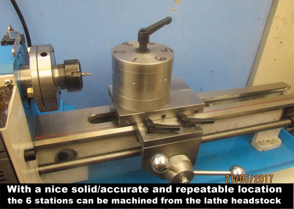
Basic premise is to make the blank turret and complete the locating/locking mechanism to ensure I get repeatable accurate location for the 6 stations
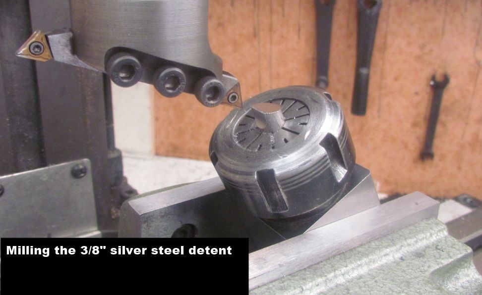
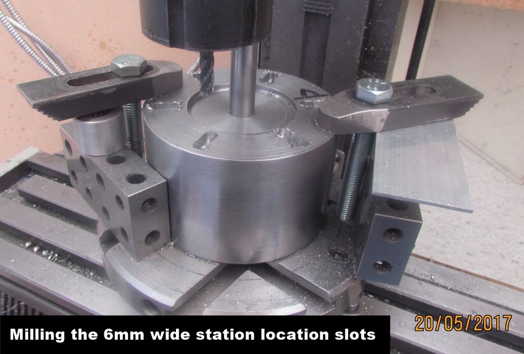
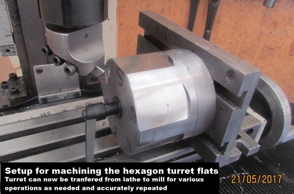
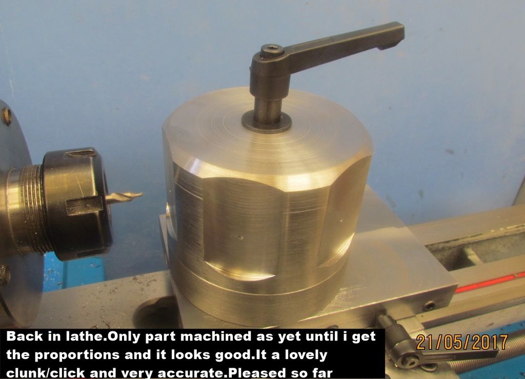
I made a more roust version of the mini lathe 4 way toolpost system then set up so I can pass the turret between lathe and mill for multiple operations with
confidence that any maching will be accurate to the 6 locations.Heres what I have done so far.The blank turret is not to size yet,it does not look right but too high.The flats need more machining and the locking handle is temporary
 
Back
Top