Back on my Mini V-8

Home Model Engine Machinist Forum

Help Support Home Model Engine Machinist Forum:

This site may earn a commission from merchant affiliate links, including eBay, Amazon, and others.

Mr.McKinney

Member
Joined
Aug 15, 2014
Messages
19
Reaction score
6
Well, after a long absence, I'm back to working on my mini V-8 engine. I'm working on generating some funds for more of the needed raw materials. But I have updated the solid model with my latest version, using an overkill 8 carbs (velocity stacks not yet shown). It's a single overhead cam engine of my own design. Most were machined manually on a Harbor Freight Rong Fu mill that I purchased many years ago. I've since upgraded to a CNC mill, which makes me a much better machinist :). I have some build photos HERE.

But here's the latest solid model version of the intake:


I started the design in 3D wireframe AutoCAD, but have recently converted most of the components to Solidworks.

Eric
 
Thanks folks. It's been a fun, albeit an infinite project.

Foketry, it is indeed without sleeve. At the time I started, I didn't even think about a sleeve. It took FOREVER to hone the cylinders. Doing it again, I'd 4th axis the block from aluminum and sleeve it. The machining would have been much easier. I'd like to dress up the outside of the block with some structures that make it look more like a traditional engine block. But I'll probably wait until I have the rest of the components completed before I do this. Pretty fun project.
 
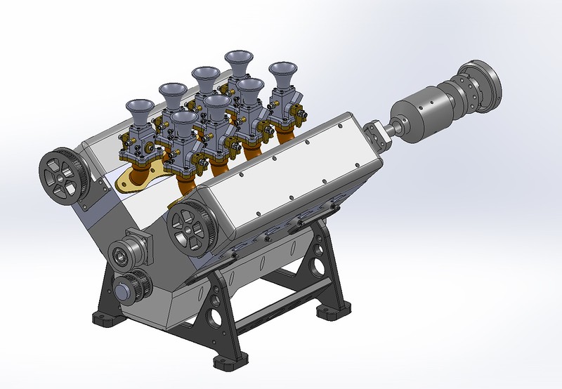
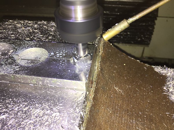
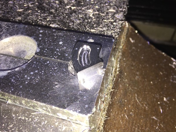
As part of this V-8 project, I started working on a small dovetail vise that I could use with my 4th axis rotary table. The problem I had with the 4th axis machining was 2-fold. First, I had issues with clearance of the tooling on the 3 Jaw chuck. This required the tool bits to be extended from the holder or the raw material to be extended from the chuck. Both of these created a whole host of other issues, with chatter being on the top of the list. The other problem is with material usage. I had to stick out the material far enough so that the tooling would clear. This consumed a lot of raw material, as the 4th axis rotary table doesn't have a through hole.

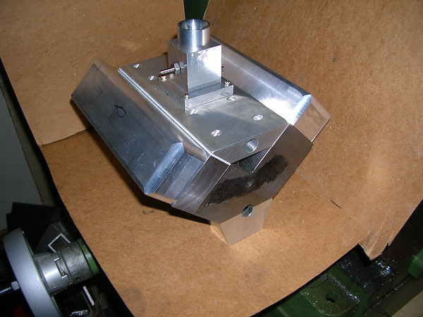
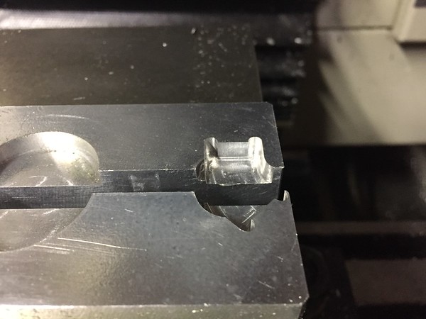
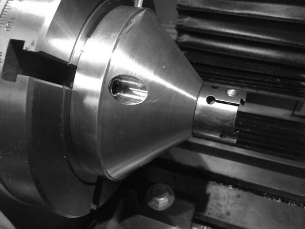
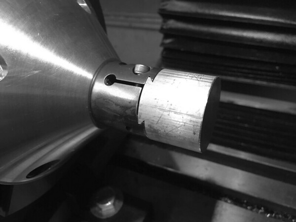
So this little dovetail vise with it's associated tapered standoff, solves a lot of problems. The down-side is that the blanks need to be machined prior to use on the dovetail vise.

I made the vise from 416 stainless, mainly because that's what I had. It's 1/5" diameter. I heat treated and tempered it. This is the first time I've used it, so I had a little fitting of the dovetail blanks. But overall, it worked well. I'll end up with only about 1/4" of waste material for each part. I was using about 4-5" per part when machining in the 3-jaw chuck.


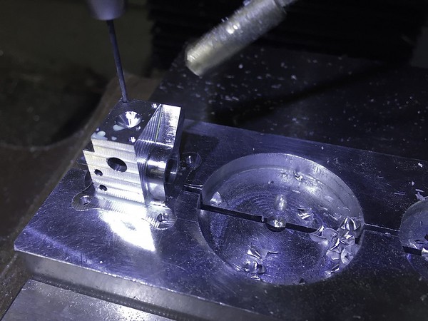
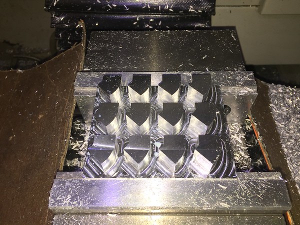
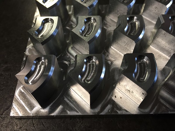
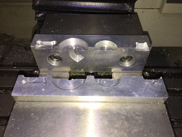
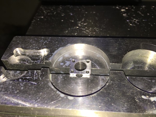
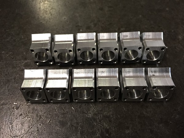
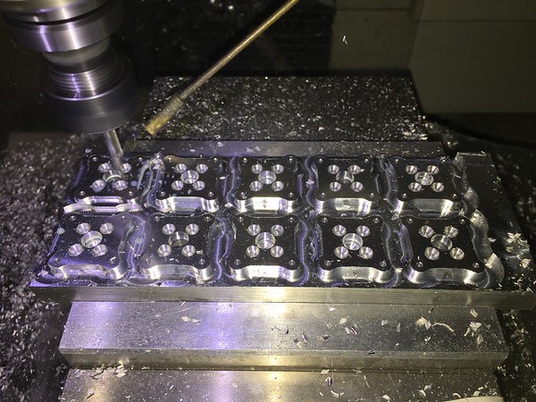
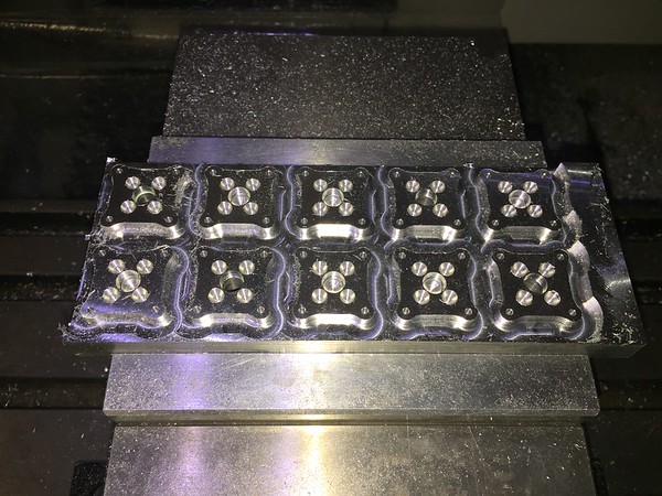
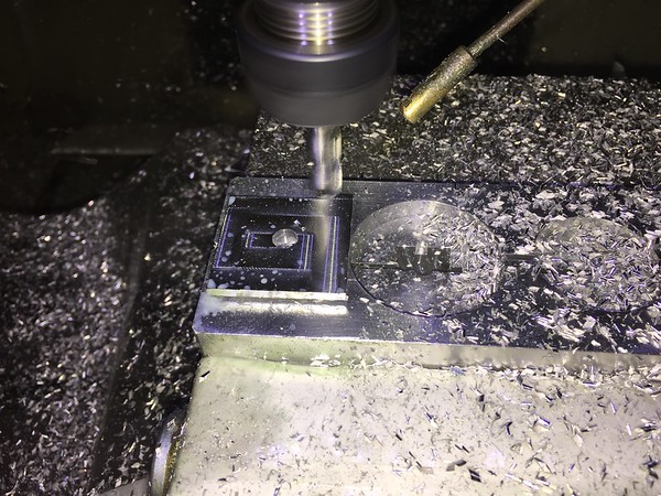
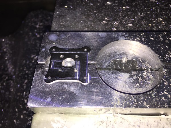
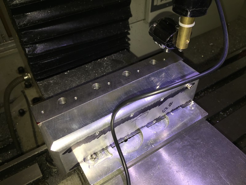
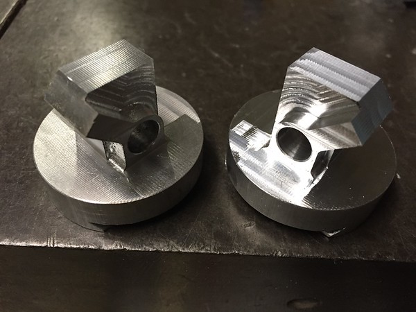
Once I finished the dovetail work, I started machining the carb bodies. These are a modification of plans I purchased of a Jerry Howell carb design. I have more machining on the base and other areas, but the 4th axis work went fairly smoothly.


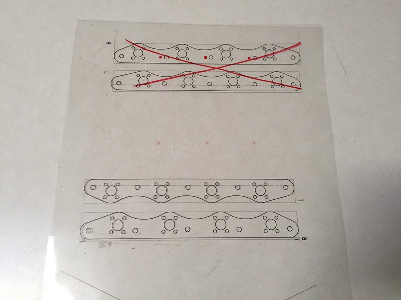
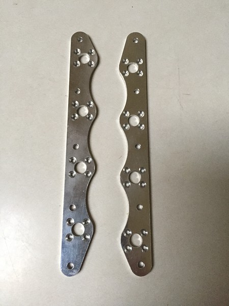
Being a glutton for punishment, I decided to make a right and left carb. So this nearly twice the CAM and set-up work. But I think it will look interesting.


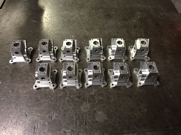
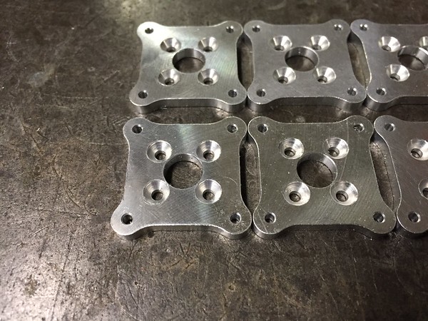
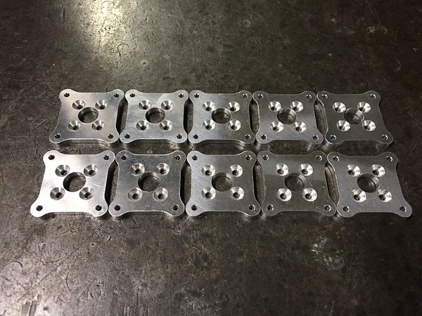
Here's a photo of the finished blanks, with one I finished a couple of years ago (upper LHS). It was tumbled, as a test. It still lacks some of the finish machining also. But you can get a general idea of the appearance of a finished part.


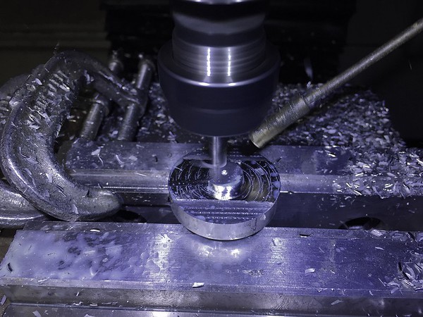
I have more photos of the machining here. And some details on the dovetail vise here

The next step is to machine the carb base, main bore and some of the feed and metering holes. I then need to machine the spray bars and butterfly and manifold parts. Due to the lack of funding, I've made some significant changes to the manifold, so it will use raw material that I have on-hand.

Hope this is interesting to folks...

Eric
 
That is a neat fixture. I had a similar issue where the chuck jaws were competing with the same real estate the cutting tool arbor/chuck wanted to be in. Something has to give, either more material stick out or longer cutting tools or... I ended up dodging that bullet with a small ER collect holder. Of course that's another tool line, but the upside is now I can hold all kinds of metric shanked end mills & such vs. being constrained to IMP world of nominal shanks like 0.25" 0.375... There is a whole world out there of high quality cutting tools from whom i suspect are comparable suppliers to the tool catalogs at significantly lower prices.

So in your application can you (easily) register the fixture to RT center along the T-slots? Or maybe just getting it close is good enough since the CNC is cutting the entire shape from the slug & no real requirement to establish center in this application?

(Very cool website btw, love your pics!)
 
I too have used ER collets, especially in the lathe when I need to do more precise work on small diameters. I chuck-up an ER tool holder in a 4 jaw and then indicate it and center it very precisely. As for centering the work in the dovetail, I have a small spring loaded pin in the base of the chuck for rough centering. It clicks the part into center. However, as you mentioned, it's somewhat irrelevant in this case, as I'm machining away all the material. But for other applications where centering is more critical, I'd probably just indicate the stock and adjust accordingly.

... and thanks for the kind words about my website :)
 
Having all of those carbs to deal with looks like a brave move, will you be starting off this way or will you get things running on a single carb first. Do you plan to run coolant passages through the engine block. ?

I like your dove tail vice idea I don't have any CNC gear but it looks as if it may be a thing I could use on my rotary table I currently have a 3 inch 3 jaw chuck used to hold small parts and there are times it does get in the way.
 
Hi Retailer,

Ha ha ha... You're probably right about the carbs. I was looking for a project to test the dovetail and work on the 4th axis. I thought it would look nice to have individual carbs. Earlier on my web page, you can see an image of a single carb and simple manifold.


This is what I'll probably use to get it running. My plan for the individual carbs was to calibrate these offline. I have a flow meter and was planning to use compressed air to test and calibrate each one for flow. For mixture, I 'll have to develop an off-line sensor system to measure this. Certainly not the easy to go, but it should be a lot of fun.

For cooling, I have some water passages in the model. These have not been machined into the block yet, as I wanted to wait and make sure that I didn't need any additional passages that would interfere with these cooling passages.

I spent the last couple weekends working on the carbs and the 45 degree carb mounts.

I flipped over the carbs and referenced the side and flange face for machining off the dovetail and machining the mounting flange/base:


These were then placed into a machinable vise jaw to machine the top features


These still lack some minor machining (reaming and tapped holes), but are getting close.


Yesterday, I finished the machining on the 45 degree bends (except tapping the myriad of #2-56 threads. Here's the platen of 45 degree bends:


These are finished on side one and need to be cut loose, flipped over and machined on the back side:


I used a machinable vise jaw to hold the parts for the other operations


I plan to machine the manifold mounting flanges and intake manifolds next. I'm digging through my materials looking for stock. My preference is always to have machined surfaces on all sides. but I may just machine these parts from 1/8" stock and see if the material is flat enough to do a grazing pass with the fly cutter (without thinning the material too much). If not, I'll make a fixture and hand-finish the mating surfaces flat.
 
I did some machining of the intake manifolds and the carb mounts.

These are both sides of the intake manifolds.


I also spent some time machining the carb mounts. I had planned to machine these from 1/4" stock but didn't have any that was the right size. So I machined them from a 1/2" scrap. I machined 10 pieces on this scrap and then flipped them over to machine off the remaining 3/8" of material. Wasteful, but it's free stock and what I had on hand. I was also able to use the same machined recess in the machinable aluminum jaws. So there are more #2-56 holes to tap, for a total over 100 (including the spares). I'll also need a little hardware before I can complete the test assembly. Then it's back on the carbs for the internal parts machining. If these don't work well for the V-8, I'll have a pile of carbs for there engine projects.

Heres the parts being machined from the 1/2" stock


Machining the stock off the back side


The finished base, held in the machinable jaws


Close-up of the finished carb bases


The carb bases and a couple of spares
 
It is very possible you are going to be severely overcarbureted. Even the Black Widow V-8s run almost too rich on two fairly small Walbro carbs. But it will be interesting to see how this all turns out. Nice job!
 
Hi Editor,

This is possible. However, the reason I chose this carb was for its small size. This carb is supposed to be good up to 1" bore x 1.25" stroke. I designed this engine with square 1" x 1" configuration. So I believe these should be compatible with this engine. Time will tell. It wouldn't be difficult to move to a 6 pack or quad carbs, if I determine that these are too much. Should be fun to figure out. I thrive on problem-solving.

Thanks for looking...
 
An interesting development in my intake manifold segment. Some years ago, I made a crude intake manifold and must have revised the location of the mounting holes on the heads. The hole locations on the heads did not match the locations on the drawings. So when I made my new intake manifolds, they didn't fit.

Uncharacteristically, I didn't update the drawings. Regardless, I needed to get some precise measurements of the current mounting hole locations on the heads. So I used a webcam mounted on my mill, to reverse engineer the locations. I located my 0,0 point and then used the DRO to get X & Y coords of each of the holes. Once I had these, I revised the design of the manifold parts. I then printed these new designs on a transparency to validate the hole positions. Then the new designs were machined.


Here's a shot of the webcam mounted on the mill


My vintage laptop that I use in the machine shop and for astronomy purposes


Here's a close-up of the video screen locating one of the holes


My validation transparency


...And the final, revised parts


I have used this webcam technique once before to validate hole positions for another CNC program. It works pretty well, but parallax in the lens view does create some issues. It would be far better to use a telecentric lens design for something like this. But this would cost more than just purchasing an optical centering tool.
 
Good one, I'll have to file that idea away for future use.
 
Echesak:
If I understand your carb sizing there is a flaw in your thinking. There is only ever one cylinder sucking on the carb at a time. So if one carb will run one cylinder then one carb is enough for the whole engine. Maybe two for a bit of backup. You'll never build any vacuum in the intake with 8 carbs. Could be wrong. It will look cool though and you can always have 6 dummies for looks. Just my 2 cents worth.
 
It looks like he has a separate intake runner for each cylinder so each carb will be fully independent and won't be trying to share vacuum. I'm glad I'm not the one trying to tune/synchronise them all though...
 

Latest posts

Back
Top