B.J. Cicada build

Home Model Engine Machinist Forum

Help Support Home Model Engine Machinist Forum:

This site may earn a commission from merchant affiliate links, including eBay, Amazon, and others.

werowance

Well-Known Member
HMEM Supporting Member
Joined
Sep 2, 2011
Messages
1,342
Reaction score
360
Well, i figure i need to try building my first engine instead of watching everyone else and day dreaming about it.

the engine i chose is the b.j. cicada, plans here: http://modelenginenews.org/plans/BJ_Cicada.pdf

i have been pondering how to go about some of the steps as well as the materials for a while, i have posted several questions reguarding all that in different sections of the forrum and have gotten great answers back. for that i want to say thank you and a warning that i have plenty more to ask.

anyway, starting on page 2 of the plans, working on the crank case and front bearing last night and this is where i got:
first picture, the material i had ordered along with cover drawing of the engine.

second picture, sawing some blanks out of the aluminum

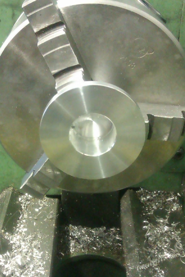
third picture, squaring up the sawn blanks to size in the lathe

fourth picture

third picture are the 2 blanks, one laying on its side is 1x1x1.60 for the crank case and the second pointing sraight up is the bearing support or as i will refer to it going forward as the "snout" of the engine which is 1x1x about 1.5 left extra on it to have room to get the live center to it over my cross slide

IMG_0065.jpg


IMG_0066.jpg


IMG_0092.jpg


IMG_0093.jpg
 
after getting some square to size aluminum blanks done, i blued them up and used my height gauge to do some layout marks on the snout part of the engine. i chucked it up and used my test indicator to get it centered then drilled and reamed to .250 hole all the way through and cut the .875 diameter circle on the rear of the snout. once i had that i went back the the height gauge and made the rest of the layout marks once i had a reference point which was the where i faced the .875 so i could start measuring up from there for the rest of the way.


picture 1 piece with some layout marks

picture 2 getting the snout centered in the 4jaw

picture 3 after drilling/reaming and cutting the .875 diameter on the snout

IMG_0125.jpg


IMG_0126.jpg


IMG_0128.jpg
 
next i took the snout with the faced .875 circle face down and used my height gauge to mark the rest of the dimensions, then as per suggestions of how to hold the piece made in questions section of this forum, i took card stock around the .875 circle and put in the chuck with the jaws only holding the .875 circle and a live center with mt3 extension across my cross slide and started cutting the .400 diameter of the snout. i cant beleive that actually held and worked. thanks to those who answered on that setup question, i think it turned out well. probably wont have anything new for at least a week, garden canning and honey bee robbing the honey, mowing, etc...cant wait till all that stuff is done so i can get some good garage time.

picture 1 snout blued and face down ready for height marking

picture 2 snout after marking with height gauge

picture 3 cutting the snout

picture 4 - .400 snout cut, and form tool to make the .200 diameter at the base of the snout -note the trumpet bell at the live center, this is the excess i left on the stock to give me room to work that get parted off as last step to make over all lenght 1.0

picture 5 - completed part minus screw holes which i will drill once i have the crank case done

IMG_0131.jpg


IMG_0132.jpg


IMG_0133.jpg


IMG_0136.jpg


IMG_0139.jpg
 
Last edited:
Werowance--You are building a very interesting engine, and I hope to follow along for the ride. I have never built a two stroke engine myself, so will be very interested in how this works out for you. If I can be of any help, just yell!!!---Brian
 
Thank you Paul and Brian. I can't seem to stop thinking about the process for each cut and the best way to do it. Up till now for most projects I have done I have had the suggested procedure for setup before the cut. And now I am without that. Drawings only


That said my next question is on the crank case. It calls for 2 holes bored. I am replying from my phone so don't have the plans in front of me but I believe both holes are a blind bore. I want to suggest what I think then hear how everyone else would do it. Thus I learn from what would have been a mistake without wasting time or material


So setup question


I have a 1x1x1.60 block ready to bore 2 holes in. Would you just drill close to close depth and to exact outside I think 7/8 without looking at plans then grind a 7/8 flat bottom drill to finish for the snout part?

Or would you drill undersized to close depth then hit with boring bar to depth and diameter then clean up the tit left in the center with either end mill slightly off center or flat bottom drill or hey even Dremel tool with stone in it?

All boring and drilling done with piece mounted in 4 jaw on lathe?

Just want to hear how you all would do it so I can put it all together and do it however works best when I get back to my machine


Thank you all for the support to all my stupid rookie questions now and in the past. I feel so much more confident with my equipment than I did a while back


Sent from my iPhone using Model Engines
 
The bottom of the .875" hole is just clearance, nothing real critical about it. I would be tempted to drill a 1/2" hole to exact depth, then run a 2 or 4 flute endmill down to the specified depth to remove the cone shape left by the drill. Then just use progressively larger end mills increasing by increments of 1/16" until I reached the 7/8" diameter. For the .625" hole I would center drill, then run a 3/8" drill thru to the previously bored .875" hole, then finish to depth with a 5/8" end mill. The endmills won't give you an exact size to 3 decimals, but they will be close. Since you are machining the mating parts, just make them to fit the hole size that your endmill gives. I would do it in the 4 jaw chuck in the lathe, and though I will probably be shot by the purists for suggesting it, I would hold the endmill in the tailstock chuck. I would run my lathe on its lowest speed, which is 115 RPM. ---I wouldn't advise doing that if you were machining steel, but for aluminum you can get away with it. It could also be done in the milling machine, but I find that if squareness and perpendicularity are issues, my cheap milling vice can not be totally trusted to hold things perfectly flat and true to the spindle. And no, I don't want to hear about the evils of holding an endmill in a chuck. I have heard it a hundred times. I do it. I get away with it.
 
Brian, so you are saying (skipping the incremental step up in size) to use an end mill labeled to size that schematics call for to cut the diameter as well as the depth to flat bottom? I am fine with that as I do it often for counter sunk screw holes. and understand the incremental step ups.

I should also say that I have at my use the following (although many not used yet) the following.

my lathe is a combo lathe milling machine. mt3 mill spindle, mt3 tail stock.

I have a crappy shop fox mill vice and agree difficult to get square and keep it square, however my cross slide has 2 t slots running perpendicular to the lathe cuck/way and 1 t slot running parallel to chuck/way. this also makes it difficult to reach short parts with my tailstock and have any room to machine the part between the chuck and tailstock.

I recently purchased and have not used a mt3 boring head and tool kit. 1/2 inch carbide tipped bars included. cheap ebay.

I have a 3/8 boring bar with carbide tip (something French made I was told by someone else was a pretty quality tool) that I got in a batch of tools online, it bores and faces really well on the little non critical quickies I have done with some slight chatter marks on the face cut of a blind hole. I was making screw driver handles and boring the hollow part of the handle from the book "machine shop projects" so those chatter marks get hidden and plugged.

but i am liking the use of an end mill as that i can handle (hopefully).

thank you again

Bryan. - "werowance"
 
As you have already made the nose piece to go into the hole and the fit in the crtankcase is quite critical I would not use endmills/slot drills to form the hole as you won't have the control over the fit.

Also on these two strokes with a crank pin that is only supported on one end the back of the crankcase acts to limit how far the conrod can move along the pin so not just a clearance you should be sloppy about

Mount the job in the 4-jaw chuck and indicate it centre. Spot or centre drill and then drill to just short of depth say 1/4, 3/8,1/2 and 5/8 if you have it.

Then take a boring bar, touch the bar against the end of the block, zero the topslide handwheel and lock the carrage. You can now bore the hole to a nice fit for the nose, start test fitting the nose in the hole as you get close to dimension incase it is a bit under/over 0.875. Then at the same settings if the boring bar is correctly on ctr height you can skim the bottom using the handwheel to get the 0.640" depth. It should be no problem to get a nice flat botton across the whole area something that plunging with a mill does not do as they tend to leave a flat cone shaped bottom.

351759.jpg


Once thats done change position in the 4-jaw and do the same with the cylinder hole.

A word of caution with your 1" stock, make sure the stock is truely square and each face flat. you can often find the sides are slightly convex which will stop your cylinder seating on a flat surface, if so take a slight skim off the top surface to clean it up and adjust the depth of teh hole to suit, also make the cylinder longer to match.

Once the two holes are done mount on the mill, indicate the centre of each hole and drill/tap the sets of 4 holes, mounting holes and lastly mill away the waste at the sides and back.
 
Jason--When you drill to depth, the sides of the resulting drilled hole are a cone at the tip. How do you remove that cone with a boring bar? Do you cut with the very end of the boring bar as opposed to the side? I have never had a lot of luck doing that. On the holes I bore, I still have to run an endmill down after drilling, at least once, to remove that coned section so I can start using a boring bar and get all the way to the bottom of the hole to leave a flat hole when I am finished.---Brian
 
How do you remove that cone with a boring bar?

The 8mm boring bar that I have mostly been using uses a 4 sided insert (a rhombus shape maybe?) with the cutting edge slightly to the front and side of the bar as a result of the angle of the insert. When I bought it I was told it would both bore and face.

With this bar I can flatten the end of a bored hole fairly easily. I drill to almost depth on the point of the drill, then face the bottom of the hole to the required depth, then keep boring to that depth until I get the required bore.

And for what it's worth Brian - I was told not to use a drill chuck to do milling because they can't handle the side forces of milling. If this is true then I would think it was perfectly acceptable to use a drill chuck on the lathe the way you described. I haven't had to yet, but I'm sure I will in the future.
 
Here you go Brian, starting top left

1. Spot drill, I only use a centre drill when I actiually need a 60deg CSK to take a centre

2. Drill out in stages to say 1/2"

3. Now take a boring bar and open up to just below finished dia and as deep as possible until the end of the tool is cutting too wide a cut

4 (2nd row) Now that there is a bit more room the bar can be used to take the depth down in steps to remove the conical base cutting from the centre out towards you.

5. same method until the bottom is flat but just a couple of thou short of depth

6. final cuts to dia followed by facing the bottom to depth from outside towards the centre.

As Cogsy says quite easily done with a bar that can cut in both directions either ground from HSS or an indexable one.

boring.jpg
 
Using the bar allows you to fine tune the fit which you can't do so easily with milling cutters.

You will recognise this off a Nemett, all three parts in the second photo push together with a gentle squeeze between finger and thumb yet stay together when held upside down

IMAG2752.jpg


IMAG2753.jpg
 
here is a picture i got off the web of a similar boring bar, mostly how the left right cut and carbide orientation on the bar is what i am comparing to mine.

my inserts have a much rounder radious with is why i think it leaves such a good finish.

oh, and on the end mill in jacobs chuck, no worries, i have a mt3 er32 chuck that will fit my tail stock.

i think ill try both suggestions on some scrap cheaper alloy aluminum first.

i hope to get a little shop time this weekend.

boring bar.jpg
 
My method seems to work great as long as you are not aiming for a specific size to 3 decimal places and you are going to make the "goes into" part after you bore the hole. You can make it to fit. If you make the "goes into" part first, then my method is totally out to lunch.---And Jason, thank you for the tutorial. My cheap brazed carbide boring bars don't have the shape required to achieve what you have shown. Next time I have a blind hole to bore I will sharpen one into the parallelogram shape you show and try that method.----Brian
 
Last edited:
well honey bees robbed and harvested, banana peppers mostly picked and pickled, half the potatoes dug, etc.... and to the garage I went yesterday.

so first challenge locating my Jacobs chuck key. grrrrr. hate when I lose it. then finally started some test cuts. no pictures as they were all failures.

all tests done on scrap cast aluminum.

test 1, drill in increments to close depth/diameter, was facing the bottom when the carbide came lose and hung, actualy bent the retaining tab on my little insert bar. no extra inserts for it on hand so on to next trial and failure.

test 2, trying the same thing using my boring head in the tailstock, those bars are half inch mounting diameter but even the largest had a lot of visibly noticible flex. these are cheap brazed tipped bars that came with the head. not likeing this idea much. hate I messed up my good boring bar in step one.

test 3, just figured id see how close a 7/8 drill bit came, I have 2 different 7/8 bits that are different brands and different materials that I bought at separate times. both cut notacably different sizes that I didn't even have measure to notice they both cut different size holes. neither of which actually hit 7/8. so possibly scratch the 7/8 flat bottom drill bit idea.

possibly test 4, kinda sorta test.... I have a 7/8 end mill that is new from a lot of tools I bought, never used it and realized now why not. I don't have a collet or anything I can chuck it up with. guess I could make a holder 7/8 to say half inch, but not right now.

the 7/8 end mill is notacably smaller than either if the 7/8 drill holes I made but until I make a cut with it I cant really be sure of what it will actually cut. I could measure with my calipers the mill but I figure It will actually cut a bit larger than what I measure due to "give" in everything.


so at this point, I want to buy another decent boring bar like I had for at least the cylinder boring to come later, what would you all do? scrap the first nose I made and make the crank case first, then remake the nose to fit? call that a learning experience. or wait and try again with another boring bar and try to do the end mill trick again?

any way, going to eat a honey biscuit and hit the hay for the night.

thanks much.
 
Last edited:
That bar you posted a picture of is not suitable for facing teh bottom of holes. The edge of teh triangle is at 90deg to the spindle axis so as soon as you get to the bottom of the hole the whole edge wants to take a big wide cut.

You need one that can turn and face. The type that take the rhomboid shaped cutters will do this like in my sketches. They are usually supplied with CCMT inserts but if you are doing a lot of aluminium then get a CCGT tip. About an 8mm or bar will do for these engines.

Should be able to get this type of bar in any country
http://www.glanze.co.uk/acatalog/Standard_Single_Boring_Tools.html
 
Although your boring bar is not really suitable, if you just angle it in the toolpost or angle the toolpost itself to create a bit of front clearance, you can quite easily face the bottom of a bore, as long as it's not too deep so as to rub the tool shank.
 
shoping for another boring bar, what do you think for this cut, 3/8 or 5/16? or some other size?

i plan on tooling up over time, but for now i just want something i can make this engine with.

thanks
 

Latest posts

Back
Top